Table of Contents
Advertisement
Quick Links
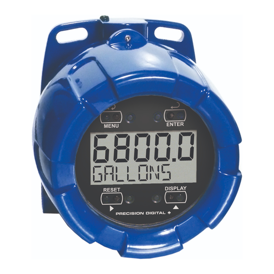
PD6800-0L1 EXPLOSION-PROOF LOOP-
POWERED PROCESS METER WITH BAR GRAPH
4-20 mA Input Loop-Powered
Modern, Sleek and Practical Enclosure
Easy-to-Read 20-Segment Tank Level Indicator
5 Digits, 0.6" (15.2 mm) Upper Display
7 Alphanumeric Character, 0.4" (10.2 mm) Lower Display
SafeTouch
®
Through-Glass Button Programming
Password Protection
32-Point, Square Root, or Exponential Linearization
Open Collector Alarm Output
Loop-Powered or External DC-Powered Backlight Standard
HART
®
Protocol Transparent
3 V Drop (6.0 V with Backlight)
Explosion-Proof, IP68, NEMA 4X Enclosure
Operates from -40 to 75°C
Order from:
C A Briggs Company
622 Mary Street; Suite 101
Warminster, PA 18974
Phone: 267-673-8117 - Fax: 267-673-8118
Sales@cabriggs.com
-
www.cabriggs.com
Advertisement
Table of Contents
Troubleshooting

Related Manuals for PRECISION DIGITAL ProtEx Pro PD6800-0L1


Summary of Contents for PRECISION DIGITAL ProtEx Pro PD6800-0L1
- Page 1 PD6800-0L1 EXPLOSION-PROOF LOOP- POWERED PROCESS METER WITH BAR GRAPH 4-20 mA Input Loop-Powered Modern, Sleek and Practical Enclosure Easy-to-Read 20-Segment Tank Level Indicator 5 Digits, 0.6" (15.2 mm) Upper Display 7 Alphanumeric Character, 0.4" (10.2 mm) Lower Display ...
- Page 2 • This product is not recommended for life support applications or applications where malfunctioning could result in personal injury or property loss. Anyone using this product for such applications does so at his/her own risk. Precision Digital Corporation shall not be held liable for damages resulting from such improper use.
-
Page 3: Introduction
PD6800-0L1 Loop-Powered Process Meter Instruction Manual INTRODUCTION The PD6800-0L1 is a rugged, explosion-proof loop-powered meter fully featured for demanding applications in hazardous areas or in the harshest environmental conditions. The bar graph representation of the process input is perfect for level applications and allows for quick assessment of current conditions. -
Page 4: Table Of Contents
PD6800-0L1 Loop-Powered Process Meter Instruction Manual Table of Contents INTRODUCTION --------------------------------------------------------------------------- 3 ORDERING INFORMATION ------------------------------------------------------------ 3 SPECIFICATIONS ------------------------------------------------------------------------- 6 General ------------------------------------------------------------------------------------------------ 6 Input ---------------------------------------------------------------------------------------------------- 7 Open Collector Output --------------------------------------------------------------------------- 7 Product Ratings and Approvals -------------------------------------------------------------- 8 ... - Page 5 PD6800-0L1 Loop-Powered Process Meter Instruction Manual Internal Calibration (ICAL) ................36 Level Input Multipoint Linearization (MULTIPT) ..........37 Information (INFO) ................... 37 OPERATION ------------------------------------------------------------------------------ 38 Front Panel Buttons Operation ------------------------------------------------------------- 38 Display Maximum, Minimum, and Input Current -------------------------------------- 39 ...
-
Page 6: Specifications
PD6800-0L1 Loop-Powered Process Meter Instruction Manual SPECIFICATIONS Except where noted all specifications apply to operation at +25°C. General DISPLAY Five digits 0.60" (15.2 mm) high, 7-segment, (-9999 to 99999) automatic lead zero blanking. Seven characters 0.4" (10.2 mm) high, 14-segment. Symbols Bar Graph which displays process input from 0-100% of scaled value. -
Page 7: Input
PD6800-0L1 Loop-Powered Process Meter Instruction Manual Input ACCURACY ±0.03% of calibrated span ±1 count, square root & programmable exponent accuracy range: 10-100% of calibrated span. MULTI-POINT 2 to 32 points LINEARIZATION PROGRAMMABLE 1.0001 to 2.9999 EXPONENT LOW FLOW CUT- 0-99999 (0 disables cutoff function) TEMPERATURE 50 PPM/C from -40 to 75C ambient DRIFT... -
Page 8: Product Ratings And Approvals
PD6800-0L1 Loop-Powered Process Meter Instruction Manual Product Ratings and Approvals Class I, Division 1, Groups B, C, D Class II, Division 1, Groups E, F, G Class III, Division 1; T6 Class I, Zone 1, AEx d IIC T6 Gb Zone 21, AEx tb IIIC T85°C Ta = -40°C to +75°C Enclosure: Type 4X &... -
Page 9: Electromagnetic Compatibility
PD6800-0L1 Loop-Powered Process Meter Instruction Manual Electromagnetic Compatibility EN 61326:2013 EMISSIONS Safety requirements for measurement, control, and la- boratory use – Industrial Group 1 Class A ISM emissions requirements Radiated Class A Emissions EN 61326:2013 IMMUNITY Safety requirements for measurement, control, and la- boratory use ±4 kV contact, ±8 kV air... -
Page 10: Installation
PD6800-0L1 Loop-Powered Process Meter Instruction Manual INSTALLATION For Installation in USA: The PD6800-0L1 must be installed in accordance with the National Electrical Code (NEC) NFPA 70. For Installation in Canada: The PD6800-0L1 must be installed in accordance with the Canadian Electrical Code CSA 22.1. All input circuits must be derived from a CSA approved Class 2 source. -
Page 11: Mounting
PD6800-0L1 Loop-Powered Process Meter Instruction Manual Mounting The PD6800-0L1 has two slotted mounting flanges that may be used for pipe mounting or wall mounting. Alternatively, the unit may be supported by the conduit using the conduit holes provided. Refer to Mounting Dimensions, page 43 for details. Do not attempt to loosen or remove flange bolts while the meter is in service. -
Page 12: Table Of Figures Figure 1. Connector Board
PD6800-0L1 Loop-Powered Process Meter Instruction Manual Connections (continued) SIGNAL + 4-20 mA signal input positive terminal connection SIGNAL - 4-20 mA signal return/negative terminal connection when not using loop powered backlight. BACKLIGHT + +9-36 VDC when powering backlight from external supply. BACKLIGHT - 4-20 mA signal return/negative terminal when using the installed loop powered backlight or ground/negative when powering... -
Page 13: Connections & Wiring Diagrams
PD6800-0L1 Loop-Powered Process Meter Instruction Manual Connections & Wiring Diagrams Signal connections are made to a four-terminal connector mounted in the base of the enclosure. The enclosure also provides one internal and one external earth grounding screw. For installations without backlight, only the two signal terminals are connected. -
Page 14: External Acknowledge Connection
PD6800-0L1 Loop-Powered Process Meter Instruction Manual Figure 4. Connections with Externally-Powered Backlight It is possible to use the same transmitter (signal loop) power supply for the externally powered backlight. The backlight circuit will draw 25 mA in addition to the loop circuit. External Acknowledge Connection External acknowledge connections are made to two terminals labeled RESET. -
Page 15: Open Collector Output Connections
PD6800-0L1 Loop-Powered Process Meter Instruction Manual Open Collector Output Connections Output connections are made to two terminals labeled OUTPUT. Connect to an input device such as alarm indicator as shown in Figure 6, or drive a relay as shown in Figure 7. -
Page 16: Setup And Programming
PD6800-0L1 Loop-Powered Process Meter Instruction Manual SETUP AND PROGRAMMING There is no need to recalibrate the meter for milliamps when first received from the factory. The meter is factory calibrated for milliamps prior to shipment. The calibration equipment is traceable to NIST standards. Overview ®... -
Page 17: Safetouch ® Buttons
PD6800-0L1 Loop-Powered Process Meter Instruction Manual ® SafeTouch Buttons The PD6800-0L1 is equipped with four sensors that operate as through-glass buttons so that it can be programmed and operated without removing the cover (and exposing the electronics) in a hazardous area. These buttons can be disabled for security by selecting the LOCK setting on the SAFE-TOUCH BUTTONS switch located on the connector board in the base of the enclosure. -
Page 18: Buttons And Display
PD6800-0L1 Loop-Powered Process Meter Instruction Manual Buttons and Display Button Description Symbol Status Symbol Menu Tank Level Indicator MENU RESET Right arrow/Reset DISPLAY Up arrow/Display Enter ENTER... - Page 19 PD6800-0L1 Loop-Powered Process Meter Instruction Manual Menu Button Press the Menu button to enter Programming Mode. Press the Menu button during Programming Mode to return to the previous menu selections. Hold the Menu button for 1.5 seconds at any time to exit Programming Mode and return to Run Mode.
-
Page 20: Main Menu
PD6800-0L1 Loop-Powered Process Meter Instruction Manual Main Menu The main menu consists of the most commonly used functions: Setup, Advanced, and Password. Press MENU button to enter Programming Mode then press the Up Arrow button to scroll through the main menu. Hold MENU, at any time, to exit and return to Run Mode. -
Page 21: Setting Up The Meter (Setup)
PD6800-0L1 Loop-Powered Process Meter Instruction Manual Setting Up the Meter (SETUP) The Setup menu is used to select: Engineering units decimal location Engineering units display scale Tank indicator full and empty values Bottom display selection Press the ENTER button to access any menu or press UP arrow button to scroll through choices. -
Page 22: Setting Numeric Values
PD6800-0L1 Loop-Powered Process Meter Instruction Manual Setting Numeric Values The numeric values are set using the RIGHT and UP arrow buttons. Press RIGHT arrow to select next digit and UP arrow to increment digit. The digit being changed blinks. Press the ENTER button, at any time, to accept a setting. Hold MENU, at any time, to exit and return to Run Mode. -
Page 23: Main Menu Display Functions & Messages
PD6800-0L1 Loop-Powered Process Meter Instruction Manual Main Menu Display Functions & Messages The meter displays various functions and messages during setup, programming, and operation. The following table shows the main menu functions and messages in the order they appear in the menu. Display Parameter Action/Setting... -
Page 24: Scaling The Meter (Scale)
PD6800-0L1 Loop-Powered Process Meter Instruction Manual Scaling the Meter (SCaLe) The 4-20 mA input can be scaled to display the process in engineering units. To scale the meter, enter the value in milliamps (mA) for input 1, and then the corresponding engineering units display value. -
Page 25: Minimum Input Span
PD6800-0L1 Loop-Powered Process Meter Instruction Manual Minimum Input Span The minimum input span is the minimum difference between input 1 and input 2 signals required to complete the calibration or scaling of the meter. The minimum span is 0.10 mA. Scale Error Message (SPN ERR) If the minimum span is not maintained, the meter will show a span error (SPN ERR) and revert to input 2, allowing the appropriate input signals to be applied. -
Page 26: Configuring The Display (Display)
PD6800-0L1 Loop-Powered Process Meter Instruction Manual Configuring the Display (DISPLAY) The lower (BOTTOM) display may be configured to display a custom tag (TAG), volume (VOLUME), volume and tag (VOL+TAG), percent of full height (PCT HT), or percent of full height and tag (PCT+TAG), or be blank (OFF). A custom tag may be up to seven alphanumeric characters programmed for identification (e.g. - Page 27 PD6800-0L1 Loop-Powered Process Meter Instruction Manual Setting the TAG (TAG) Any bottom display setting that includes a tag will require the tag to be entered. dsply botnm botnm botnm The fully alphanumeric values for the tag are set using the RIGHT button to select the digit, the UP and RIGHT arrow buttons to select the digit reading, and the ENTER button to confirm and select the next digit.
-
Page 28: Setting Up The Password (Passwrd)
PD6800-0L1 Loop-Powered Process Meter Instruction Manual Setting Up the Password (PASSWRD) The Password menu is used to program a five-digit password to prevent unauthorized changes to the programmed parameter settings. A password protected meter will display LOCKED when the MENU button is pressed. Locking the Meter Enter the Password menu and program a five-digit password. -
Page 29: Disabling Password Protection
PD6800-0L1 Loop-Powered Process Meter Instruction Manual Disabling Password Protection To disable the password protection, access the Password menu and enter the correct password, as shown below. If the correct five-digit password is entered, the meter displays the message UNLOCKD (unlocked) and the protection is disabled until a new password is programmed. If the password entered is incorrect, the meter displays the message LOCKED and returns to Run Mode. -
Page 30: Advanced Features Menu (Advance)
PD6800-0L1 Loop-Powered Process Meter Instruction Manual Advanced Features Menu (ADVANCE) To simplify the setup process, functions not needed for most applications are located in the Advanced Features Menu. Access the Advanced Features Menu by pressing ENTER at the ADVANCE menu in the Main Menu defined on page 20. The Advanced Features Menu is used to select: 1. -
Page 31: Advanced Features Menu & Display Messages
PD6800-0L1 Loop-Powered Process Meter Instruction Manual Advanced Features Menu & Display Messages The following table shows the Advanced features menu functions and messages in the order they appear in the menu. Display Parameter Action/Setting OUTPUT Enter output menu Output Disable output ALARM Enter alarm output menu Alarm Output... - Page 32 PD6800-0L1 Loop-Powered Process Meter Instruction Manual Display Parameter Action/Setting ICAL Enter internal reference calibration Internal Calibration Calibrate input at 4 mA 4. 0 00 4.000 mA Calibrate input at 20 mA 20. 0 00 20.000 mA Error Error with calibration point 1 and 2 span Error Span SPAN MULTIPT...
-
Page 33: Alarm Output (Output)
PD6800-0L1 Loop-Powered Process Meter Instruction Manual Alarm Output (OUTPUT) The PD6800-0L1 is equipped with an NPN open collector output that may be set up for high or low alarm trip point based on the level display (LEVEL) or the volume scale (VOLUME). -
Page 34: Input Signal Filter (Filter)
PD6800-0L1 Loop-Powered Process Meter Instruction Manual Input Signal Filter (FILTER) The noise filter is available for unusually noisy signals that cause an unstable process variable display. The noise filter averages the input signal over a certain period. The filter level can be set to low (LO), medium (MED), high (HI), or off (OFF). The higher the filter setting, the longer the averaging time and so the longer the display may take to find its final value. -
Page 35: Level Input Live Signal Calibration (Lvl Cal)
PD6800-0L1 Loop-Powered Process Meter Instruction Manual Level Input Live Signal Calibration (LVL CAL) The meter can be calibrated using a current source instead of scaling. This process will override previously programmed scaling of the level display. The use of a calibrated signal source is strongly recommended. -
Page 36: Internal Calibration (Ical)
PD6800-0L1 Loop-Powered Process Meter Instruction Manual Internal Calibration (ICAL) There is no need to recalibrate the meter when first received from the factory. The meter is factory calibrated prior to shipment. The calibration equipment is traceable to NIST standards The internal calibration is the meter’s master calibration that makes scaling the meter without a signal source possible. -
Page 37: Level Input Multipoint Linearization (Multipt)
PD6800-0L1 Loop-Powered Process Meter Instruction Manual Level Input Multipoint Linearization (MULTIPT) This menu enables multipoint linearization for scaling and calibrating of the level display. Setting MULTIPT to ENABLE will alter the level display Scaling (See Scaling the Meter on page 24) and Level Calibration (See Level Input Live Signal Calibration on page 35) menus to include a Number of Points (NO PTS) parameter before entering Input 1. -
Page 38: Operation
PD6800-0L1 Loop-Powered Process Meter Instruction Manual OPERATION Front Panel Buttons Operation Button Description Symbol Press to Enter or Exit Programming Mode MENU RESET Used to Reset Maximum and Minimum Values Press to Cycle Displaying Maximum Value, DISPLAY Minimum Value, and Input Current in mA Press to Resume Run Mode in Lower Display Press to Acknowledge Alarm (if Enabled) ENTER... -
Page 39: Display Maximum, Minimum, And Input Current
PD6800-0L1 Loop-Powered Process Meter Instruction Manual Display Maximum, Minimum, and Input Current The maximum and minimum values and the measured input loop current may be displayed temporarily on the lower display. To display these values, press the DISPLAY button. The meter will display the word MAXIMUM on the bottom display and the maximum value reached (since the last maximum reset) on the top display. -
Page 40: Reset Meter To Factory Defaults
PD6800-0L1 Loop-Powered Process Meter Instruction Manual Reset Meter to Factory Defaults When the parameters have been changed in a way that is difficult to determine what’s happening, it might be better to start the setup process from the factory defaults. Instructions to load factory defaults: Enter the Advanced Features Menu. -
Page 41: Factory Defaults & User Settings
PD6800-0L1 Loop-Powered Process Meter Instruction Manual Factory Defaults & User Settings The following table shows the factory setting for most of the programmable parameters on the meter. Next to the factory setting, the user may record the new setting for the particular application. Model: ______________ S/N: _______________ Date: _________ Parameter... -
Page 42: Troubleshooting
PD6800-0L1 Loop-Powered Process Meter Instruction Manual TROUBLESHOOTING Due to the many features and functions of the meter, it’s possible that the setup of the meter does not agree with what an operator expects to see. If the meter is not working as expected, refer to the Diagnostics menu and consult the recommendations described below. -
Page 43: Mounting Dimensions
PD6800-0L1 Loop-Powered Process Meter Instruction Manual MOUNTING DIMENSIONS All units: inches [mm] 3.35 [85.1] 2.25 [57.1] 0.32 [8.2] 5.65 [143.5] 5.25 [133.4] Figure 9. Enclosure Dimensions – Front View... -
Page 44: Figure 10. Enclosure Dimensions - Side Cross Section View
PD6800-0L1 Loop-Powered Process Meter Instruction Manual 3.35 [85.0] 4.15 [105.5] 4.86 [123.5] 3.22 [81.9] Figure 10. Enclosure Dimensions – Side Cross Section View... -
Page 45: Quick User Interface Reference
PD6800-0L1 Loop-Powered Process Meter Instruction Manual QUICK USER INTERFACE REFERENCE Pushbutton Function MENU Go to programming mode or leave programming. Hold for 5 seconds to enter Advanced Features menu directly. RIGHT Arrow Move to next digit. Go to previous menu or alphanumeric char- acter selection. - Page 46 PD6800-0L1 Loop-Powered Process Meter Instruction Manual...
-
Page 47: Eu Declaration Of Conformity
SIRA 10 ATEX M462 ATEX Notified Body for Quality Assurance: Sira Certification Service, NB 0518 Unit 6, Hawarden Industrial Park Hawarden, Deeside, CH5 3US, UK Signed for and on behalf of Precision Digital Corporation: Name: Jeffrey Peters Company: Precision Digital Corporation... - Page 48 PD6800-0L1 Loop-Powered Process Meter Instruction Manual How to Contact Precision Digital For Technical Support: Call: (800) 610-5239 or (508) 655-7300 Fax: (508) 655-8990 Email: support@predig.com For Sales Support: Call: (800) 343-1001 or (508) 655-7300 Fax: (508) 655-8990 Email: sales@predig.com ...
Need help?
Do you have a question about the ProtEx Pro PD6800-0L1 and is the answer not in the manual?
Questions and answers