Table of Contents
Advertisement
Quick Links
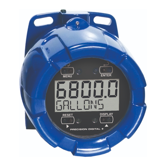
PD6800 EXPLOSION-PROOF
LOOP-POWERED PROCESS METER
4-20 mA Input Loop-Powered
Modern, Sleek and Practical Enclosure
5 Digits, 0.7" (17.8 mm) Upper Display
7 Alphanumeric Character, 0.4" (10.2 mm) Lower Display
SafeTouch
Password Protection
32-Point, Square Root, or Exponential Linearization
Loop-Powered or External DC-Powered Backlight Standard
®
HART
Protocol Transparent
3 V Drop (6.0 V with Backlight)
Explosion-Proof, IP68, NEMA 4X Enclosure
Operates from -40 to 75°C
PRECISION DIGITAL CORPORATION
89 October Hill Road • Holliston MA 01746 USA
Tel (800) 343-1001 • Fax (508) 655-8990
®
Through-Glass Button Programming
www.predig.com
®
Advertisement
Table of Contents

Related Manuals for PRECISION DIGITAL PD6800


Summary of Contents for PRECISION DIGITAL PD6800
- Page 1 PD6800 EXPLOSION-PROOF LOOP-POWERED PROCESS METER 4-20 mA Input Loop-Powered Modern, Sleek and Practical Enclosure 5 Digits, 0.7" (17.8 mm) Upper Display 7 Alphanumeric Character, 0.4" (10.2 mm) Lower Display ® SafeTouch Through-Glass Button Programming ®...
- Page 2 Disclaimer The information contained in this document is subject to change without notice. Precision Digital makes no representations or warranties with respect to the contents hereof; and specifically disclaims any implied warranties of merchantability or fitness for a particular purpose.
-
Page 3: Introduction
PD6800 Loop-Powered Process Meter Instruction Manual INTRODUCTION The PD6800 is a rugged, explosion-proof loop-powered meter fully featured for demanding applications in hazardous areas or in the harshest environmental conditions. The meter derives all of its power from the 4-20 mA loop. It is ®... -
Page 4: Table Of Contents
PD6800 Loop-Powered Process Meter Instruction Manual Table of Contents INTRODUCTION ---------------------------------------------------------------------- 3 ORDERING INFORMATION ------------------------------------------------------- 3 SPECIFICATIONS -------------------------------------------------------------------- 6 General ------------------------------------------------------------------------------------------- 6 Input ----------------------------------------------------------------------------------------------- 7 Product Ratings and Approvals --------------------------------------------------------- 8 Electromagnetic Compatibility ----------------------------------------------------------- 9 ... - Page 5 PD6800 Loop-Powered Process Meter Instruction Manual Low-Flow Cutoff (CUTOFF) ................. 33 Input Signal Filter (FILTER) ............... 33 Internal Calibration (ICAL) ................. 34 Information (INFO) ..................34 OPERATION -------------------------------------------------------------------------- 35 Front Panel Buttons Operation -------------------------------------------------------- 35 ...
-
Page 6: Specifications
PD6800 Loop-Powered Process Meter Instruction Manual SPECIFICATIONS Except where noted all specifications apply to operation at +25°C. General Five digits 0.70" (17.8 mm) high, 7-segment, DISPLAY (-9999 to 99999) automatic lead zero blanking. Seven characters 0.4" (10.2 mm) high, 14 segment. -
Page 7: Input
PD6800 Loop-Powered Process Meter Instruction Manual 5.65" x 5.25" x 4.86" (W x H x D) OVERALL (144 mm x 133 mm x 124 mm) DIMENSIONS 5.00 lbs (80 oz, 2.27 kg) WEIGHT 3 years parts and labor WARRANTY Input ±0.03% of calibrated span ±1 count,... -
Page 8: Product Ratings And Approvals
This information is contained within the serial number with the first four digits representing the year and month in the YYMM format. For European Community: The PD6800 must be installed in accordance with the ATEX directive 94/9/EC, and the product certificate Sira 10ATEX1116X. -
Page 9: Electromagnetic Compatibility
PD6800 Loop-Powered Process Meter Instruction Manual Electromagnetic Compatibility EN 61326:2006 EMISSIONS Safety requirements for measurement, control, and laboratory use – Industrial Group 1 Class A ISM emissions requirements Radiated Class A Emissions EN 61326:2006 IMMUNITY Safety requirements for measurement, control, and laboratory use ±4 kV contact,... -
Page 10: Installation
PD6800 Loop-Powered Process Meter Instruction Manual INSTALLATION For Installation in USA: The PD6800 must be installed in accordance with the National Electrical Code (NEC) NFPA 70. For Installation in Canada: The PD6800 must be installed in accordance with the Canadian Electrical Code CSA 22.1. All input circuits must be derived from a CSA approved Class 2 source. -
Page 11: Mounting
PD6800 Loop-Powered Process Meter Instruction Manual Mounting The PD6800 has two slotted mounting flanges that may be used for pipe mounting or wall mounting. Alternatively, the unit may be supported by the conduit using the conduit holes provided. Refer to Mounting Dimensions, page 39 for details. -
Page 12: Figure 1. Connector Board
PD6800 Loop-Powered Process Meter Instruction Manual Connections (continued) 4-20 mA signal input positive terminal connection SIGNAL + 4-20 mA signal return/negative terminal connection when not SIGNAL - using loop powered backlight. +9-36 VDC when powering backlight from external supply. BACKLIGHT +... -
Page 13: Connections & Wiring Diagrams
PD6800 Loop-Powered Process Meter Instruction Manual Connections & Wiring Diagrams Signal connections are made to a four-terminal connector mounted in the base of the enclosure. The enclosure also provides one internal and one external earth grounding screw. For installations without backlight, only the two signal terminals are connected. -
Page 14: Figure 3. Connections With Loop-Powered Backlight
PD6800 Loop-Powered Process Meter Instruction Manual SAFE-TOUCH BACKLIGHT BUTTONS POWER + - + - LOOP UNLOCK LOCK 9-36 VDC SIGNAL BACKLIGHT 4-20 mA Transmitter Slide Switch to Power LOOP Supply Figure 3. Connections with Loop-Powered Backlight SAFE-TOUCH BACKLIGHT BUTTONS POWER... -
Page 15: Setup And Programming
PD6800 Loop-Powered Process Meter Instruction Manual SETUP AND PROGRAMMING There is no need to recalibrate the meter for milliamps when first received from the factory. The meter is factory calibrated for milliamps prior to shipment. The calibration equipment is certified to NIST standards. -
Page 16: Safetouch Buttons
SafeTouch Buttons The PD6800 is equipped with four sensors that operate as through-glass buttons so that it can be programmed and operated without removing the cover (and exposing the electronics) in a hazardous area. These buttons can be disabled for security by selecting the LOCK setting on the switch located on the connector board in the base of the enclosure. -
Page 17: Buttons And Display
PD6800 Loop-Powered Process Meter Instruction Manual Buttons and Display MENU ENTER RESET DISPLAY Button Description Symbol Status Symbol High Alarm Set Menu MENU RESET Low Alarm Set Right arrow/Reset DISPLAY Password Enabled Up arrow/Display Enter ENTER Press the Menu button to enter or exit the Programming Mode at any time. -
Page 18: Main Menu Display Functions & Messages
PD6800 Loop-Powered Process Meter Instruction Manual Main Menu Display Functions & Messages The meter displays various functions and messages during setup, programming, and operation. The following table shows the main menu functions and messages in the order they appear in the menu. -
Page 19: Main Menu
PD6800 Loop-Powered Process Meter Instruction Manual Main Menu The main menu consists of the most commonly used functions: Setup, Password, and Service. Press MENU button to enter Programming Mode then press the Up Arrow button to scroll through the main menu. -
Page 20: Setting Numeric Values
PD6800 Loop-Powered Process Meter Instruction Manual Setting Numeric Values The numeric values are set using the Right and Up arrow buttons. Press Right arrow to select next digit and Up arrow to increment digit. The digit being changed blinks. Press the Enter button, at any time, to accept a setting or MENU button to exit without saving changes. -
Page 21: Setting The Decimal Point (Dec. P T)
PD6800 Loop-Powered Process Meter Instruction Manual Setting the Decimal Point (Dec. P t) Decimal point may be set with up to four decimal places or with no decimal point. Pressing the Right arrow moves the decimal point one place to the right until no decimal point is displayed. -
Page 22: Programming The Meter (Prog)
PD6800 Loop-Powered Process Meter Instruction Manual Programming the Meter (PRoG) It is very important to read the following information, before proceeding to program the meter: There is no need to recalibrate the meter for milliamps when first received from the factory. -
Page 23: Scaling The Meter (Scale)
PD6800 Loop-Powered Process Meter Instruction Manual Scaling the Meter (SCale) The 4-20 mA input can be scaled to display the process in engineering units. A signal source is not needed to scale the meter; simply program the inputs and corresponding display values. -
Page 24: Calibrating The Meter (Cal)
PD6800 Loop-Powered Process Meter Instruction Manual Calibrating the Meter (Cal) To scale the meter without a signal source refer to Scaling the Meter (SCale), page 23. The meter can be calibrated to display the process in engineering units by applying the appropriate input signal and following the calibration procedure. -
Page 25: Re-Calibrating The Internal Calibration Reference (Ical)
PD6800 Loop-Powered Process Meter Instruction Manual Minimum Input Span The minimum input span is the minimum difference between input 1 and input 2 signals required to complete the calibration or scaling of the meter. The minimum span is 0.10 mA. -
Page 26: Setting Up The Password (Passwrd)
PD6800 Loop-Powered Process Meter Instruction Manual Setting Up the Password (PASSWRD) The Password menu is used to program a five-digit password to prevent unauthorized changes to the programmed parameter settings. The lock symbol is displayed to indicate that settings are protected. -
Page 27: Disabling Password Protection
PD6800 Loop-Powered Process Meter Instruction Manual Disabling Password Protection To disable the password protection, access the Password menu and enter the correct password twice, as shown below. The meter is now unprotected until a new password is entered. Enter Password Run Mode 3024. -
Page 28: Advanced Features Menu
PD6800 Loop-Powered Process Meter Instruction Manual Advanced Features Menu To simplify the setup process, functions not needed for most applications are located in the Advanced features menu. Press and hold the MENU button for five seconds to access the Advanced features menu. -
Page 29: Advanced Features Menu & Display Messages
PD6800 Loop-Powered Process Meter Instruction Manual Advanced Features Menu & Display Messages The following table shows the Advanced features menu functions and messages in the order they appear in the menu. Display Parameter Action/Setting INDICAT Enter Indication (Alarm) menu Indicate... -
Page 30: Indication (Indicat)
PD6800 Loop-Powered Process Meter Instruction Manual For instructions on how to program numeric values see Setting Numeric Values, page 20. Indication (INDICAT) The Indication menu is used to enable and set up a high or low alarm indication on the screen. When alarm indication is enabled, the HI and LO symbols are used accompanied by a flashing display. -
Page 31: Advanced Function Selection (Functn)
PD6800 Loop-Powered Process Meter Instruction Manual Advanced Function Selection (FUNCTN) The Advanced Function menu is used to select the advanced function to be applied to the input: linear, square root, programmable exponent, or round horizontal tank volume calculation. The multi-point linearization is part of the linear function selection. -
Page 32: Square Root Linearization (Squar)
PD6800 Loop-Powered Process Meter Instruction Manual LnEAR FUNCTN PROGRAM PROGRAM inP 1 dsp 1 0000. 0 DSPLY 1 INP 2 Figure 6. Multi-Point Linearization Menu Square Root Linearization (Squar) The square root function can be used to linearize the signal from a differential pressure transmitter and display flow rate in engineering units. -
Page 33: Low-Flow Cutoff (Cutoff)
PD6800 Loop-Powered Process Meter Instruction Manual Low-Flow Cutoff (CUTOFF) The low-flow cutoff feature allows the meter to be programmed so that the often- unsteady output from a differential pressure transmitter, at low flow rates, always displays zero on the meter. The default cutoff is zero to prevent negative readings, but this may be overridden to allow them. -
Page 34: Internal Calibration (Ical)
PD6800 Loop-Powered Process Meter Instruction Manual Internal Calibration (ICAL) There is no need to recalibrate the meter for milliamps when first received from the factory. The meter is factory calibrated for milliamps prior to shipment. The calibration equipment is certified to NIST standards. -
Page 35: Operation
PD6800 Loop-Powered Process Meter Instruction Manual OPERATION Front Panel Buttons Operation Button Description Symbol Press to enter or exit Programming Mode or exit Max/Min readings MENU RESET Press to reset Max/Min readings DISPLAY Press to display Max/Min readings alternately Press to display Max or Min reading... -
Page 36: Maximum & Minimum Readings (Maximum & Minimum)
PD6800 Loop-Powered Process Meter Instruction Manual Maximum & Minimum Readings (MAXIMUM & MINIMUM) The maximum and minimum (peak & valley) readings reached by the process are stored in the meter since the last reset or power-up. The meter shows MAXIMUM or MINIMUM to differentiate between run mode and max/min display. -
Page 37: Factory Defaults & User Settings
PD6800 Loop-Powered Process Meter Instruction Manual Factory Defaults & User Settings The following table shows the factory setting for most of the programmable parameters on the meter. Next to the factory setting, the user may record the new setting for the particular application. -
Page 38: Troubleshooting
PD6800 Loop-Powered Process Meter Instruction Manual TROUBLESHOOTING The rugged design and the user-friendly interface of the meter should make it unusual for the installer or operator to refer to this section of the manual. If the meter is not working as expected, refer to the recommendations below. -
Page 39: Mounting Dimensions
PD6800 Loop-Powered Process Meter Instruction Manual MOUNTING DIMENSIONS All units: inches [mm] 3.35 [85.1] 2.25 [57.1] 0.32 [8.2] 5.65 [143.5] 5.25 [133.4] Figure 7. Enclosure Dimensions – Front View... -
Page 40: Figure 8. Enclosure Dimensions - Side Cross Section View
PD6800 Loop-Powered Process Meter Instruction Manual 3.35 [85.0] 4.15 [105.5] 4.86 [123.5] 3.22 [81.9] Figure 8. Enclosure Dimensions – Side Cross Section View... -
Page 41: Quick User Interface Reference
PD6800 Loop-Powered Process Meter Instruction Manual QUICK USER INTERFACE REFERENCE Pushbutton Function Go to Programming Mode or leave Programming, Advanced Menu Features, and Max/Min Modes. Right Arrow Move to next digit or decimal point position. Reset Total. Up Arrow Move to next selection or increment digit. Go to Max/Min Mode. - Page 42 PD6800 Loop-Powered Process Meter Instruction Manual...
-
Page 43: Ec Declaration Of Conformity
PD6800 Loop-Powered Process Meter Instruction Manual EC DECLARATION OF CONFORMITY Issued in accordance with ATEX Directive 94/9/EC Precision Digital Corporation Manufacturer: 89 October Hill Rd Ste 5 Holliston, MA 01746 USA PD6800 Series Process Meter Device: Sira Certification Service, notified body no. 0518... - Page 44 PD6800 Loop-Powered Process Meter Instruction Manual How to Contact Precision Digital For Technical Support: Call: (800) 610-5239 or (508) 655-7300 Fax: (508) 655-8990 Email: support@predig.com For Sales Support: Call: (800) 343-1001 or (508) 655-7300 Fax: (508) 655-8990 Email: sales@predig.com ...
Need help?
Do you have a question about the PD6800 and is the answer not in the manual?
Questions and answers