Table of Contents
Advertisement
Quick Links
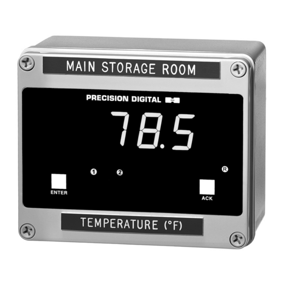
PD655 Large Display Process Meter With
Rate/Totalizer/Batch Control Features
•
Easy Single Button Scaling (SBS)
•
4-20 mA, 1-5 V, 0-5 V, or 0-10 V Field Selectable Inputs
•
Large 1.0" (25.4 mm) High LEDs
•
Full Six Digit Display for Total, 4½ Digit + Extra Zero for Process/Rate
•
Total Displayed in any Engineering Unit
•
Display in Engineering Units; Rate per Second, Minute, Hour, or Day
•
Scale Without a Calibrator
•
11-Point Calibration for Non-Linear Inputs
•
Automatic Square Root and Programmable Exponent
•
Low-Flow Cutoff
•
NEMA 4X Impact-Resistant Glass Filled Polycarbonate Enclosure
•
Two 24 VDC Isolated Power Supplies
•
115 or 230 VAC Power, Field Selectable; 24 VDC Optional
•
Quick Preset Change Feature for Batch Control
•
Pump Alternation Control Feature
•
2 or 4 Relays + 4-20 mA Output Options
C A Briggs Company
622 Mary Street; Suite 101
Warminster, PA 18974
Phone: 267-673-8117 - Fax: 267-673-8118
Sales@cabriggs.com
Instruction Manual
Order from:
-
www.cabriggs.com
Advertisement
Table of Contents

Related Manuals for PRECISION DIGITAL PD655


Summary of Contents for PRECISION DIGITAL PD655
- Page 1 PD655 Large Display Process Meter With Rate/Totalizer/Batch Control Features Instruction Manual • Easy Single Button Scaling (SBS) • 4-20 mA, 1-5 V, 0-5 V, or 0-10 V Field Selectable Inputs • Large 1.0" (25.4 mm) High LEDs • Full Six Digit Display for Total, 4½ Digit + Extra Zero for Process/Rate •...
- Page 2 Model PD655 Large Display Process Meter Instruction Manual Visit our Website http://www.predig.com...
-
Page 3: Table Of Contents
Model PD655 Large Display Process Meter Instruction Manual Table of Contents INTRODUCTION ----------------------------------------------------------------------- 7 Key Features ----------------------------------------------------------------------------------- 7 Typical Applications ------------------------------------------------------------------------- 8 Ordering Information ------------------------------------------------------------------------ 8 Safety Notice ----------------------------------------------------------------------------------- 9 Specifications -------------------------------------------------------------------------------- 10 Basic Process Meter --------------------------------------------------------------------- 10 Rate/Totalizer/Batch Controller Features ------------------------------------------- 11... - Page 4 Model PD655 Large Display Process Meter Instruction Manual Overview -------------------------------------------------------------------------------- 41 Set Display to Rate (dSPy r) ------------------------------------------------------ 41 Low-flow Cutoff Programming (Cutoff) ---------------------------------------- 42 Totalizer Programming ------------------------------------------------------------------ 43 Overview -------------------------------------------------------------------------------- 43 Set Display for Total (dSPy t) ----------------------------------------------------- 43...
- Page 5 Model PD655 Large Display Process Meter Instruction Manual Resetting Total Automatically via User Selectable Preset -------------- 71 Relays Operation --------------------------------------------------------------------------- 72 Overview ------------------------------------------------------------------------------------ 72 Relays Auto Initialization ---------------------------------------------------------------- 72 Fail-Safe Operation ---------------------------------------------------------------------- 72 Front Panel LEDs ------------------------------------------------------------------------- 73 Acknowledging Relays ------------------------------------------------------------------ 75...
- Page 6 Model PD655 Large Display Process Meter Instruction Manual List of Figures Figure 1. Removing the Display Board ............18 Figure 2. Input Power Label ................ 20 Figure 3. Connections and Jumper Diagram ..........21 Figure 4. Options Board Connectors and J5 Jumper ....... 22 Figure 5.
-
Page 7: Introduction
Model PD655 Large Display Process Meter Instruction Manual INTRODUCTION This instrument is an analog input process meter with flow rate, totalizer, and batch control capabilities housed in a rugged, impact-resistant glass filled polycarbonate, NEMA 4X enclosure. It accepts the common process signals such as 4-20 mA, 0-5 VDC, 1-5 VDC, and 0-10 VDC. -
Page 8: Typical Applications
Model PD655 Large Display Process Meter Instruction Manual Typical Applications Level: Sump Pump Control Water Tank Level Round Horizontal Tank Volume Measurement Well Draw-down Lift Station Control Flow: Square Root Extraction from Differential Pressure Transmitter Programmable Exponent for Weirs and Flumes... -
Page 9: Safety Notice
Disclaimer The information contained in this document is subject to change without notice. Precision Digital makes no representations or warranties with respect to the contents hereof, and specifically disclaims any implied warranties of merchantability or fitness for a particular purpose. -
Page 10: Specifications
Model PD655 Large Display Process Meter Instruction Manual Specifications Except where noted all specifications apply to operation at +25°C. Basic Process Meter INPUTS Field selectable: 4-20 mA, 0-20 mA, 0-5 V, 1-5 V, 0-10 V DISPLAY Six digit, 1.0" (25.4 mm) high efficiency red LED. -
Page 11: Rate/Totalizer/Batch Controller Features
Model PD655 Large Display Process Meter Instruction Manual PEAK HOLD Captures the maximum or peak process/rate and displays it via MAX (DISPLAY PEAK) the front panel ENTER button Dspy p PEAK HOLD OR Front panel flashing “R” LED MAX INDICATION LOCKOUT Jumper JP1 labeled “LOCK”... -
Page 12: Options
Model PD655 Large Display Process Meter Instruction Manual TOTAL Programmable from 0.00001 to 59999 CONVERSION FACTOR TOTALIZER Calculates total based on rate and field programmable total conversion factor to display total in engineering units. Time base must be selected according to time units in which rate is displayed. - Page 13 Model PD655 Large Display Process Meter Instruction Manual FAIL-SAFE Relay coils are energized in non-alarm condition. In case of power failure, relays will go to alarm state. Fail-safe operation OPERATION may be disabled, by removing jumper J5 located on the Options Board.
- Page 14 Model PD655 Large Display Process Meter Instruction Manual Isolated 4-20 mA Transmitter Output CALIBRATION The transmitter output can be calibrated so that a 4 mA output is produced for any process/rate measured by the meter. The RANGE 20 mA output may correspond to any process/rate that is at least 501 counts greater or smaller than the process/rate corresponding to 4 mA.
-
Page 15: Display Functions And Messages
Model PD655 Large Display Process Meter Instruction Manual Display Functions and Messages The meter displays various functions and messages during operation and programming. The following table shows the various displayed functions and messages with their description. Display Parameter Description/Comments Low voltage... - Page 16 Model PD655 Large Display Process Meter Instruction Manual Display Parameter Description/Comments Linear input Indicates linear input was selected. LInear Minute Sets time base to display rate in units per minute. Sets meter for 2 to 11 calibration points. No PtS...
-
Page 17: Setup And Programming
Model PD655 Large Display Process Meter Instruction Manual SETUP AND PROGRAMMING Overview To set up and program the meter, it is necessary to disassemble the Display Board. See disassembling instructions in the next pages. Setting up and programming the meter involves four basic steps:... -
Page 18: Disassembling The Meter
Model PD655 Large Display Process Meter Instruction Manual Disassembling the Meter To perform the steps described above, it is necessary to partially disassemble the meter. The Main Board may remain attached to enclosure’s base even during conduit hub installation if proper precautions are taken. -
Page 19: Jumper Configuration
Model PD655 Large Display Process Meter Instruction Manual Jumper Configuration Overview Before programming the meter, it is necessary to configure three jumper arrays. The jumper arrays are used for setting type of input signal (4-20 mA, 0-5 V, or 0-10 V); locking out the programmed settings, enable relay acknowledgement (ACK), and setting relay fail-safe operation. -
Page 20: Power Selection
Model PD655 Large Display Process Meter Instruction Manual Power Selection Overview Power Selection involves the following: Changing to 230 VAC power if needed. Factory default is 115 VAC. Labeling the meter as to how it will be powered: 115 VAC, 230 VAC, or 24 VDC. -
Page 21: Connections
Model PD655 Large Display Process Meter Instruction Manual Connections Overview The following connections are made to removable screw terminal connectors supplied with each meter: Power Connections Signal Connections Enter, Acknowledgement, and Reset Total Connections Relays Connections 4-20 mA Output Connections Figure 3. -
Page 22: Wiring Instructions
Model PD655 Large Display Process Meter Instruction Manual Figure 4. Options Board Connectors and J5 Jumper Wiring Instructions Refer to Figure 3 and Figure 4 for connectors’ location. All field connections to be made with insulated copper wire, either solid or stranded. -
Page 23: Power Connections
Model PD655 Large Display Process Meter Instruction Manual Power Connections Refer to Changing from 115 to 230 VAC Power, page 20, to make sure meter is set up to accept proper voltage before applying power. Disconnect power to the meter before making any connections. -
Page 24: Signal Connections
Model PD655 Large Display Process Meter Instruction Manual Signal Connections Signal connections are made to a 10-position connector J1 on the Main Board. This connector also includes connections for Enter, Acknowledgement, Reset Total, and Common. Refer to Figure 3 for location of J1. - Page 25 Model PD655 Large Display Process Meter Instruction Manual 3-Wire Transducer Figure 8. Three-Wire Transducer Powered by Meter Figure 9. Direct Voltage Signal Connections Unregulated 18 V (nominal) @ 200mA (maximum) 3-Wire Transmitter Figure 10. Optional Unregulated Supply Connections...
-
Page 26: Enter, Acknowledgement, And Reset Total Connections
Model PD655 Large Display Process Meter Instruction Manual Enter, Acknowledgement, and Reset Total Connections Enter, acknowledgement, and reset total terminals provide a convenient method to remotely access the following functions: Terminal Function Programs meter via the front panel menu Acknowledges or resets relays, exit menu... -
Page 27: Isolated 4-20 Ma Output Option Connections
Model PD655 Large Display Process Meter Instruction Manual Isolated 4-20 mA Output Option Connections The meter can be equipped with an isolated 4-20 mA output signal option that can be programmed to produce a 4-20 mA output for virtually any process/rate display with at least a 501 count span. -
Page 28: Programming
Model PD655 Large Display Process Meter Instruction Manual Programming Overview The meter is programmed using the ENTER button and three jumper arrays. The ENTER button is used to calibrate the meter, program various totalizer functions, and set alarm trip and reset points. The jumper arrays are used for programming the input signal, lockout, relays acknowledge enable, and relays fail-safe operation. - Page 29 Model PD655 Large Display Process Meter Instruction Manual Figure 15. Jumper Arrays and Status LED Identification ENTER Button The ENTER button is used to program the meter for various functions and is located behind the front panel on the Display Board, It is labeled SW2 in Figure 15 above.
-
Page 30: Five Basic Digit/Display Setting Instructions
Model PD655 Large Display Process Meter Instruction Manual Five Basic Digit/Display Setting Instructions If the flashing display is OK, to accept it, press ENTER before it stops flashing. If the flashing display is not OK, (or if ENTER was not pressed in time to accept it), wait for the first digit to flash. - Page 31 Model PD655 Large Display Process Meter Instruction Manual Press ENTER Press ENTER when CALIb appears; LInear Square Pro9 r scroll Select LInear 29999 appears; select dec point no. PtS then Inpt1 flashes; Apply input 1 signal (e.g. 4 mA) Inpt 2 flashes;...
-
Page 32: Basic Meter Programming
Model PD655 Large Display Process Meter Instruction Manual Basic Meter Programming Overview The meter is programmed using three jumper arrays and the ENTER button. The ENTER button is used to calibrate the meter, program various totalizer functions, and set alarm set and reset points. The jumper arrays are used for programming the input signal, lockout, relay fail-safe operation, and relay acknowledge enable. -
Page 33: Select Calibration Method
Model PD655 Large Display Process Meter Instruction Manual Select Calibration Method For best results, allow the meter to warm up for at least 30 minutes. The meter may be calibrated using an external signal source such as a calibrator or scaled using the internal source with the I-CAL feature. With I-CAL, a 4-20 mA input can be scaled for any display range without applying a signal. -
Page 34: Scale Or Calibrate The Meter
Model PD655 Large Display Process Meter Instruction Manual Scale or Calibrate the Meter The meter may be scaled without applying an external signal source or calibrated by applying an external signal source. Scale Using Internal Calibration (I-CAL) Note To simplify programming, write down the desired programming values prior to attempting to program the meter. -
Page 35: Minimum Input Span (Error Message)
Model PD655 Large Display Process Meter Instruction Manual Set the first calibration point Inpt 1 Input 1 (INPT 1) flashes indicating that the meter is ready to be programmed for the input for the first calibration point. Press ENTER. Set the input for the first calibration point 04. - Page 36 Model PD655 Large Display Process Meter Instruction Manual Set the second calibration point Inpt 2 Input 2 (INPT 2) flashes indicating that the meter is ready to be programmed for the input for the second calibration point. Press ENTER. Set the input for the second calibration point 20.
- Page 37 Model PD655 Large Display Process Meter Instruction Manual Select programmable root Pro9 r To select programmable root, press ENTER when function is displayed. The meter will now advance to setting the exponent value. Program exponent 1. 6 070 Program exponent value. Exponent value must be greater than 1.0000 and smaller than 3.0000.
-
Page 38: Calibrate Using External Calibration (E-Cal)
Model PD655 Large Display Process Meter Instruction Manual Calibrate Using External Calibration (E-CAL) Note To simplify programming, write down the desired programming values prior to attempting to program the meter. The Programmed Parameter Settings form located at the back of this manual provides a convenient method to record the user settings;... - Page 39 Model PD655 Large Display Process Meter Instruction Manual Apply the signal for the first calibration point Inpt 1 Input 1 (INPT 1) flashes indicating that the meter is ready to accept a signal for the first calibration point. Apply the desired signal, typically 4 mA, and press ENTER.
-
Page 40: Round Horizontal Tank Calibration Points
Model PD655 Large Display Process Meter Instruction Manual Round Horizontal Tank Calibration Points Number of Points: 10 Maximum Error: 0.3% F.S. Input Display (% Volume) 4.00 0.00 4.80 1.80 7.20 6.00 7.20 14.20 9.20 28.10 14.80 71.80 16.80 85.80 18.00 92.80... -
Page 41: Rate Meter Programming
Model PD655 Large Display Process Meter Instruction Manual Rate Meter Programming Overview The meter can also be used to display flow rate. In addition to the scaling and calibration procedures described above, the only setup required for this is setting the meter to display rate, and programming the low-flow cutoff if required. -
Page 42: Low-Flow Cutoff Programming (Cutoff)
Model PD655 Large Display Process Meter Instruction Manual Low-flow Cutoff Programming (Cutoff) The low-flow cutoff feature allows the meter to be programmed so that the often- unsteady output from a differential pressure transmitter at low-flow rates always displays zero on the meter. -
Page 43: Totalizer Programming
Model PD655 Large Display Process Meter Instruction Manual Totalizer Programming Overview The meter can also be used to display total flow. There are five functions to be programmed to allow the meter to act as a flow totalizer: Set Display to Total... -
Page 44: Set Rate Time Base (T Base)
Model PD655 Large Display Process Meter Instruction Manual Set Rate Time Base (t baSE) To act as a totalizer, the meter must be programmed with the same time base as the flow transmitter. The time base is the time unit in which the rate is displayed. -
Page 45: Set Totalizer Decimal Point (Tot Dp)
Model PD655 Large Display Process Meter Instruction Manual Set totalizer conversion factor Tot Cf Press ENTER, then press ENTER again when the totalizer conversion factor (Tot Cf) function appears. Set the totalizer conversion factor decimal point 99999. 9 Immediately after tot Cf is selected, the display will show then six numbers. -
Page 46: Set Alternating Total/Rate Display
Model PD655 Large Display Process Meter Instruction Manual Set Alternating Total/Rate Display The display may be programmed to automatically toggle between rate and total every ten seconds. To set up the alternating display select no (n) for both, display rate (dSPy r) and display total (dSPy t) under Display Selection (... -
Page 47: Set Point Setup And Programming
Model PD655 Large Display Process Meter Instruction Manual Set Point Setup and Programming Overview The meter is available with 4 alarm points and corresponding front panel status LEDs as a standard feature. The front panel LEDs are useful for alarm applications that require visual notification only. -
Page 48: Set Relays For Manual Or Automatic Reset
Model PD655 Large Display Process Meter Instruction Manual Set Relays for Manual or Automatic Reset Jumper array JP5 located on the Display Board is used to program the relays so they can be reset manually. See Figure 15 on page 29 for location of this jumper array. -
Page 49: Assigning Set Points To Process/Rate Or Total (Setup)
Model PD655 Large Display Process Meter Instruction Manual Assigning Set Points to Process/Rate or Total (setup) The optional relays can be assigned to respond to the process/rate or the accumulated total using the setup function. Process/rate relays may be set for latching or non-latching operation. -
Page 50: Rate Or Total, Latching Or Non-Latching Relays
Model PD655 Large Display Process Meter Instruction Manual Rate or Total, Latching or Non-Latching Relays Note To simplify programming, write down the desired programming values prior to attempting to program the meter. The Programmed Parameter Settings form located at the back of this manual provides a convenient method to record the user settings;... - Page 51 Model PD655 Large Display Process Meter Instruction Manual Select total R or t After selecting t for total, the display will show set point 2 then (Set 2), press ENTER to set up set point 2 or wait and the display will move to the next set point.
-
Page 52: Programming Internal Total Reset And Delay (Delay)
Model PD655 Large Display Process Meter Instruction Manual Select total when the first set point was assigned to R or t total then After selecting t for total for second set point, the display will show preset offset (OFFSEt) press ENTER to set up this OFFSET function. -
Page 53: Setting Relays For Pump Alternation (Altern)
Model PD655 Large Display Process Meter Instruction Manual Setting Relays for Pump Alternation (ALtERn) Setting relays for pump alternation control ALtErn At the end of the SetuP menu, the display will show alternate (ALtErn), press ENTER to set up this function. If... -
Page 54: Programming Alarm Points And Presets (Setpts)
Model PD655 Large Display Process Meter Instruction Manual Programming Alarm Points and Presets (SEtPtS) Overview The SEtPtS menu is used to program the following functions: Set and reset points for alarms assigned to process/rate (thus determining High or Low alarm status and deadband.) -
Page 55: Programming Alarm And Preset Values (Setpts)
Model PD655 Large Display Process Meter Instruction Manual Programming Alarm and Preset Values (SEtPtS) Alarm, preset, and preset offset values are programmed under the SEtPtS menu, one at a time, starting with set point 1. The set points are programmed according to whether they were assigned to process/rate or total during the setup program. - Page 56 Model PD655 Large Display Process Meter Instruction Manual Figure 20. Programming Status of Set Point LEDs Assigned to Total Note To simplify programming, write down the desired programming values prior to attempting to program the meter. The Programmed Parameter Settings form located at the back of this manual provides a convenient method to record the user settings;...
- Page 57 Model PD655 Large Display Process Meter Instruction Manual Set the display for alarm # (1,2,3 or 4) set point 070. 0 0 The entire display will flash for three seconds. For then instructions see Five Basic Digit/Display Setting Instructions, page 30.
- Page 58 Model PD655 Large Display Process Meter Instruction Manual Press ENTER, then press ENTER again when the SEtPtS set points (SetPtS) function appears. Preset values for set points assigned to total with offset If a set point was assigned to total with offset...
-
Page 59: Ma Isolated Output Option Programming (Output)
Model PD655 Large Display Process Meter Instruction Manual 4-20 mA Isolated Output Option Programming (output) Programming the 4-20 mA transmitter output option for the meter does not require the use of a calibrator. The transmitter output can be calibrated so that a 4 mA output is produced for any process/rate measured by the meter. -
Page 60: Lockout And Display Selection Programming
Model PD655 Large Display Process Meter Instruction Manual Lockout and Display Selection Programming Overview The meter provides the user with the ability to restrict modification of programming values and to exclude menu titles from appearing during the menu scroll. Restricting modification of the programming values is accomplished by installing the lockout jumper (JP1). -
Page 61: Display Selection (Dsplay)
Model PD655 Large Display Process Meter Instruction Manual Display Selection (dSPLAy) The dSPLAy menu is used to remove menu titles from appearing during the menu scroll. This feature is useful for eliminating unused menu titles from the menu scroll; making it impossible to perform certain functions, and making the display automatically toggle between process/rate and total. -
Page 62: Alternating Display
Model PD655 Large Display Process Meter Instruction Manual Notes: User may program which of these routine titles are active during operation and which ones are not. See below for instructions. Note: Selections made through the display menu (dSPLAY) can be made with or without the lockout jumper installed, but only become active when the lockout jumper is installed. -
Page 63: Include Or Exclude Menu Titles From Menu Scroll
Model PD655 Large Display Process Meter Instruction Manual Include or Exclude Menu Titles From Menu Scroll Press ENTER, then press ENTER again when the Dsplay display (Dsplay) function appears. The meter will now scroll through the various menu titles that can be included or excluded. -
Page 64: Operation
Model PD655 Large Display Process Meter Instruction Manual OPERATION Overview This instrument is an analog input process meter with flow rate, totalizer, and batch control capabilities. It accepts the common process signals such as 4-20 mA, 0-5 VDC, 1-5 VDC, and 0-10 VDC. It displays these signals in any engineering unit on a 1.0"... -
Page 65: Two Types Of Display: Process/Rate And Total
Model PD655 Large Display Process Meter Instruction Manual The four alarm status LEDs indicate alarm condition only and do not represent relay status when set points are set up for non-latching relay mode. For instance, if alarm 1 is programmed for a high alarm at 500 with manual reset of the relays and the operator resets the relays when the display reads 650, the #1 LED will stay on until the display falls below 500. -
Page 66: Basic Meter Operation
Model PD655 Large Display Process Meter Instruction Manual Basic Meter Operation Overview In its most basic form, the meter provides a digital display in engineering units of any process variable from a transmitter, such as temperature, pressure, level, flow, etc. The meter is calibrated for the appropriate range, the output of the transmitter is connected to the meter and the meter displays the process. -
Page 67: Display Peak & Reset Peak Operation (Dspy P & Rset P)
Model PD655 Large Display Process Meter Instruction Manual Display Peak & Reset Peak Operation (dSPY P & rSEt P) The meter captures the highest process/rate reading and displays it through the display peak (dspy p) menu function. The peak value may be reset using the reset peak (rset p) menu function. -
Page 68: Rate Meter Operation
Model PD655 Large Display Process Meter Instruction Manual Rate Meter Operation Overview The meter can also be used to display flow rate and is available with a low-flow cutoff feature. Totalizer functions can be excluded from the menu scroll through the dsplay menu function, if the user is not interested in total display. -
Page 69: Totalizer Operation
Model PD655 Large Display Process Meter Instruction Manual Totalizer Operation Overview The meter provides a display of accumulated flow total by integrating the flow rate input to the meter and multiplying this value by a user-defined totalizer conversion factor. The total is displayed on a six-digit display that is capable of reading to 999,999. -
Page 70: Applications Using Total Conversion Factor And Time Base
Model PD655 Large Display Process Meter Instruction Manual Applications Using Total Conversion Factor and Time Base The following tables illustrate the effect various total conversion factors and time bases have on the operation of the meter: Application #1 Time Total... -
Page 71: Totalizer Reset
Model PD655 Large Display Process Meter Instruction Manual Totalizer Reset The totalizer may be reset in any of three ways: Via the front panel ENTER button External contact closure Automatically via highest preset value Resetting Total Using the ENTER Button Press ENTER, then press ENTER again when the 87652. -
Page 72: Relays Operation
Model PD655 Large Display Process Meter Instruction Manual Relays Operation Overview The Relays capabilities of the meter expand its usefulness beyond simple indication to provide users with alarm and control functions. These capabilities include front panel alarm status LEDs as well as either 2 or 4 optional relays. -
Page 73: Front Panel Leds
Model PD655 Large Display Process Meter Instruction Manual Front Panel LEDs Figure 26. Front Panel LED Indicator Locations The LEDs on the front panel provide status for the following: Status Status Alarm 1 Set Point Indicator Alarm 2 Reset Point Indicator... - Page 74 Model PD655 Large Display Process Meter Instruction Manual Relay key legend for following tables Relay condition Tripped Reset Acknowledged The On and Off keys do not refer to the status of the relay’s coil, which depends on the fail-safe mode selected.
-
Page 75: Acknowledging Relays
Model PD655 Large Display Process Meter Instruction Manual Latching Relay Manual reset only after signal passes reset point JP5(1-4 off) Condition Relay Normal Alarm Ack (No effect) Normal In this application, the meter is set up for manual reset only after the signal passes the reset point of the latching relay. -
Page 76: Simple On/Off Control With 100% Deadband Operation
Model PD655 Large Display Process Meter Instruction Manual Simple On/Off Control with 100% Deadband Operation The meter can be used as a simple On/Off controller as the following illustrates: Using the meter for sump-pump control and alarm control Relay #1 turns the main... - Page 77 Model PD655 Large Display Process Meter Instruction Manual Relay #3 trips the High Level Alarm at 7500 gallons and resets at 6900 gallons. Relay #4 trips the Low Level Alarm at 495 gallons and it resets at 750 gallons.
-
Page 78: Manual Batch Control Operation
Model PD655 Large Display Process Meter Instruction Manual Manual Batch Control Operation The meter can be used for simple manual batch control as the following illustrates: The valve and External Switch KEY Legend is as shown: Both valves are open to fill the barrel: Meter displays barrel contents. -
Page 79: Automatic Batch Control Operation
Model PD655 Large Display Process Meter Instruction Manual Automatic Batch Control Operation The meter can be used for automatic batch control as the following illustrates: The valve KEY Legend is as shown: Both valves are opened to fill the barrel. The top valve is the full flow valve, the bottom valve the restricted flow valve. -
Page 80: Delay On Release (Delay)
Model PD655 Large Display Process Meter Instruction Manual Delay on Release (delay) The meter can be programmed so that when the highest preset value is reached the total will automatically reset to zero (Automatic Batch Control). A delay on release can be programmed to reset the total relays after the delay has elapsed. -
Page 81: Pump Alternation Control
Model PD655 Large Display Process Meter Instruction Manual Pump Alternation Control For pump control applications where two similar pumps are used to control the level of a tank or a well, it is desirable to have the two pumps operate alternately. -
Page 82: Switching Inductive Loads
Model PD655 Large Display Process Meter Instruction Manual Switching Inductive Loads The relay contacts on the Options Board are already protected with suppression components (snubbers). If additional suppression is required, this suppression can be obtained with RC networks assembled by the user or purchased as a complete assembly. Refer to... -
Page 83: 4-20 Ma Output Operation
Model PD655 Large Display Process Meter Instruction Manual 4-20 mA Output Operation Overview The meter can be equipped with an isolated 4-20 mA output option that can be programmed to produce a 4-20 mA signal for virtually any process/rate display with at least a 501-count span. -
Page 84: Installation
Model PD655 Large Display Process Meter Instruction Manual INSTALLATION The meter overall dimensions are as shown: Figure 29. Overall Dimensions Notes: Overall dimensions: 6.7" x 5.5" x 3.7" (170 mm x 140 mm x 95 mm) The bottom of the box is tapered down on all sides by 0.05" (1.27 mm). -
Page 85: Wall Mounting Dimensions
Model PD655 Large Display Process Meter Instruction Manual Wall Mounting Dimensions There are four mounting holes on the rear of the enclosure. They are used to mount the instrument to a wall. The dimensions for the mounting holes are shown in the following figure. -
Page 86: Panel Mounting Instructions
Model PD655 Large Display Process Meter Instruction Manual Panel Mounting Instructions For applications where it is required to mount the meter into a panel, the PDA6554 panel mounting kit is available (see Ordering Information on page 8). (4) SELF TAPPING (4) MTG. -
Page 87: Option Card Removal & Installation
Model PD655 Large Display Process Meter Instruction Manual OPTION CARD REMOVAL & INSTALLATION Meter options are installed at the factory. To disable relays’ fail-safe operation, it is necessary to remove the Display Board to gain access to the Options Board. - Page 88 Model PD655 Large Display Process Meter Instruction Manual Figure 35. Installing Option Board Instructions: Disconnect power to the meter prior to removing the front cover. Remove Display Board and detach Board from ribbon cable connector. Remove Main Board from the base by removing four mounting screws.
-
Page 89: Programmed Parameter Settings
Model PD655 Large Display Process Meter Instruction Manual PROGRAMMED PARAMETER SETTINGS The following table shows the factory setting for most of the programmable parameters on the meter. Next to the factory setting, the user may record the new setting for the particular application. - Page 90 Model PD655 Large Display Process Meter Instruction Manual Parameter Display Factory User Setting Setting Total reset External e rst mode total reset Set point 1000 Set 1 values 4000 Set 2 70. 0 0 Set 3 (Reset 3) 60. 0 0 90.
- Page 91 Model PD655 Large Display Process Meter Instruction Manual User Multi-Point Scaling Table Parameter Display User Setting Input 1 InPt 1 Display 1 dspy 1 Input 2 InPt 2 Display 2 dspy 2 Input 3 InPt 3 Display 3 dspy 3...
- Page 92 Model PD655 Large Display Process Meter Instruction Manual User Set Point Setup and Programming Table Parameter Display User Setting Set point 1 SET 1 latCH Set point 2 SET 2 latCH OFFSEt Set point 3 SET 3 latCH OFFSEt Set point 4...
-
Page 93: Diagnostic Feature ( Dia9 )
Model PD655 Large Display Process Meter Instruction Manual Diagnostic Feature ( dIA9 Overview The Diagnostic menu in the meter provides an easy way to view and write down the parameter settings. The information gathered through the diagnostic menu will be helpful to determine if a wrong setting is causing the operation of the meter to be undesirable. -
Page 94: Other Precision Digital Products
PD202 General Purpose Digital Pressure Gauge PD213-224 Industrial Digital Pressure Gauges (FM & CSA) PD233-253 Precision Digital Test Pressure Gauges (FM & CSA) PD603 Sabre P Low-Cost Process Meter (UL Listed) PD644 Javelin D High-Voltage DC Panel Meter (UL Listed) PD655 1.0"... - Page 95 Model PD655 Large Display Process Meter Instruction Manual NOTES...
- Page 96 Model PD655 Large Display Process Meter Instruction Manual How to Contact Precision Digital • For Technical Support please call: (800) 610-5239 or (508) 655-7300 fax: (508) 655-8990 e-mail: support@predig.com • For Sales Support or to place an order please call: (800) 343-1001 or (508) 655-7300 fax: (508) 655-8990 e-mail: sales@predig.com...
Need help?
Do you have a question about the PD655 and is the answer not in the manual?
Questions and answers