Sign In
Upload
Manuals
Brands
PRECISION DIGITAL Manuals
Measuring Instruments
Helios PD2-7000-7H7
PRECISION DIGITAL Helios PD2-7000-7H7 Manuals
Manuals and User Guides for PRECISION DIGITAL Helios PD2-7000-7H7. We have
1
PRECISION DIGITAL Helios PD2-7000-7H7 manual available for free PDF download: Instruction Manual
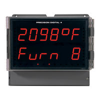
PRECISION DIGITAL Helios PD2-7000-7H7 Instruction Manual (52 pages)
Large Display Temperature Meter
Brand:
PRECISION DIGITAL
| Category:
Measuring Instruments
| Size: 3 MB
Table of Contents
Limited Warranty
2
Table of Contents
3
Table of Figures
4
Introduction
4
Ordering Information
5
Specifications
5
General
5
Temperature Input
6
Relays
6
Isolated 4-20 Ma Transmitter Output
7
Serial Communications
7
Modbus ® RTU Serial Communications
7
Digital Input & Output Terminal
7
Compliance Information
8
Safety
8
Safety Information
9
Installation
9
Unpacking
9
Wall Mounting Instructions
10
Mounting Dimensions
10
Figure 1. Meter Mounting Holes
10
Figure 2. Meter Dimensions - Side View
10
Figure 3. Meter Dimensions - Front View
10
Pipe Mounting Instructions
11
Figure 4. Vertical Pipe Mount Assembly
11
Figure 5. Horizontal Pipe Mount Assembly
11
Connections
12
Connectors Labeling
12
Power Connections
12
Figure 6. Fully Loaded PD2-7000 Connections
12
Figure 7. Power Connections
12
Signal Connections
13
Figure 8. Thermocouple Input Connections
13
Figure 9. Three-Wire RTD Input Connections
13
Figure 10. Two-Wire RTD Input Connections
13
Figure 11. Four-Wire RTD Input Connections
13
Connections for Averaging RTD Sensors
14
Modbus RTU Serial Communications
14
Relay Connections
14
Figure 12. Average Temperature RTD Input
14
Figure 13. Relay Connections
14
Switching Inductive Loads
15
Figure 14. AC and DC Loads Protection
15
Figure 15. Low Voltage DC Loads Protection
15
RS485 Output Connections
16
Figure 16. RS-422 or RS-485 Wiring
16
Figure 17. RS-485 Two-Wire Multi-Drop Wiring
17
Figure 18. Connections for RS485 Connector to Serial Converter
17
Figure 19. Three-Wire RS485 Connection
17
Digital I/O Connections
18
F4 Digital Input Connections
18
Figure 20. Digital Input and Output Connections
18
Figure 21. F4 Digital Input Connections
18
4-20 Ma Output Connections
19
Analog Output Transmitter Power Supply
19
Interlock Relay Feature
19
Figure 22. 4-20 Ma Output Connections
19
Figure 23. Interlock Connections
19
Setup and Programming
20
Overview
20
Programming Buttons and Status LED Indicators
21
Meterview ® Pro Software
22
Meterview Pro Installation
22
Display Functions & Messages
23
Main Menu
25
Setting Numeric Values
25
Setting up the Meter (Setup)
26
Setting the Input Signal (Input)
27
Selecting the Temperature Scale (F or C)
27
Setting the Decimal Point (Dec Pt)
27
Setting the Display Parameter & Intensity (Dsplay)
27
Setting the Input Units or Custom Tags (Units)
28
Setting the Relay Operation (Relay)
29
Setting the Relay Action
30
Programming Set and Reset Points
30
Setting Fail-Safe Operation
31
Programming Time Delay
31
Relay Action for Loss of 4-20 Ma Input (Loop Break)
31
Relay and Alarm Operation Diagrams
31
High Alarm Operation (Set > Reset)
31
Low Alarm Operation (Set < Reset)
31
High Alarm with Fail-Safe Operation (Set > Reset)32
32
Low Alarm with Fail-Safe Operation (Set < Reset)
32
Relay Alternation Operation
32
Relay Sampling Operation
33
Signal Loss or Loop Break Relay Operation
33
Time Delay Operation
33
Relay Operation Details
34
Overview
34
Relays Auto Initialization
34
Fail-Safe Operation
34
Front Panel Leds
34
Latching and Non-Latching Relay Operation
35
Non-Latching Relay (Auto)
35
Non-Latching Relay (A-Man)
35
Latching Relay (Latch)
35
Latching Relay (Lt-Clr)
35
Acknowledging Relays
36
Setting up the Interlock Relay (Force On) Feature
36
Figure 24. Acknowledge Relays with Function Key or Digital Input
36
Scaling the 4-20 Ma Analog Output (Aout)
37
Reset Menu (Reset)
37
Control Menu (Contrl)
37
Setting up the Password (Pass)
38
Protecting or Locking the Meter
38
Making Changes to a Password Protected Meter
39
Disabling Password Protection
39
Advanced Features Menu
40
Advanced Features Menu & Display Messages
40
Offset Adjust (Adjust)
42
Recalibration of the Meter (T CAL)
42
Noise Filter (Filter)
43
Noise Filter Bypass (Bypass)
43
Rounding Feature (Round)
43
Modbus RTU Serial Communications (Serial)
43
Analog Output Programming (Aoutpr)
44
Programmable Function Keys User Menu (User)
45
Internal Source Calibration (ICAL)
46
Meter Operation
48
Buttons Operation
48
Function Key Operation
48
Digital Input Operation
48
Maximum/Minimum Readings
49
Troubleshooting
49
Diagnostics Menu (Diag)
49
Determining Software Version
50
Reset Meter to Factory Defaults
50
Factory Defaults & User Settings
51
Troubleshooting Tips
52
Advertisement
Advertisement
Related Products
PRECISION DIGITAL Helios PD2-7000 Series
PRECISION DIGITAL Helios PD2-7000-6H0
PRECISION DIGITAL Helios PD2-7000-6H7
PRECISION DIGITAL Helios PD2-7000-7H0
PRECISION DIGITAL PD213
PRECISION DIGITAL PD224
PRECISION DIGITAL Helios PD2-6060
PRECISION DIGITAL PD2-6400-6H7
PRECISION DIGITAL Helios PD2-6100-6H0
PRECISION DIGITAL Helios PD2-6100-7H7
PRECISION DIGITAL Categories
Measuring Instruments
Controller
Monitor
Scanner
Network Hardware
More PRECISION DIGITAL Manuals
Login
Sign In
OR
Sign in with Facebook
Sign in with Google
Upload manual
Upload from disk
Upload from URL