Table of Contents
Advertisement
A6 S Arc Master
A6 S G Master
A6 S Compact 500
A6 SFE1 / A6 SFE2 / A6 SGE1/
A6 SFE1C
112101103105107109111102021110025108024042106023061104022041100020040060001
Bruksanvisning
Brugsanvisning
Bruksanvisning
Käyttöohjeet
Instruction manual
Betriebsanweisung
Manuel d'instructions
0456 562 101 2009- -03- -09
Gebruiksaanwijzing
Instrucciones de uso
Istruzioni per l'uso
Manual de instruções
Ïäçãßåò ÷ñÞóåùò
Instrukcja obs³ugi
Valid for serial no. 321
Advertisement
Table of Contents

Related Manuals for ESAB A6 S Arc Master


Summary of Contents for ESAB A6 S Arc Master
- Page 1 A6 S Arc Master A6 S G Master A6 S Compact 500 A6 SFE1 / A6 SFE2 / A6 SGE1/ A6 SFE1C 112101103105107109111102021110025108024042106023061104022041100020040060001 Bruksanvisning Gebruiksaanwijzing Brugsanvisning Instrucciones de uso Bruksanvisning Istruzioni per l’uso Käyttöohjeet Manual de instruções Instruction manual Ïäçãßåò ÷ñÞóåùò...
- Page 2 SVENSKA ..........DANSK .
-
Page 3: Table Of Contents
ENGLISH 1 DIRECTIVE ............2 SAFETY . -
Page 4: Directive
Fax: + 46 584 12336 SAFETY Users of ESAB welding equipment have the ultimate responsibility for ensuring that anyone who works on or near the equipment observes all the relevant safety precautions. Safety precautions must meet the requirements that apply to this type of welding equipment. The following recommen- dations should be observed in addition to the standard regulations that apply to the workplace. -
Page 5: Introduction
All the automatic welding machines included in this instruction manual are designed for SAW and MIG/MAG welding of butt and fillet joints. ESAB’s welding heads are of the A6 S type and are intended for use in combination with A2--A6 Process Controller and ESAB’s welding power sources LAF and TAF. -
Page 6: Technical Data
Technical data A6 SFE1 A6 SFE1 A6 SFE2 A6 SGE1 A6 SFE1C MIG/MAG LD D20 HD D35 HD D35 800 A 1500 A 1500 A 600 A 1500 A Rated load 100% 1000 A 60 % AC/DC AC/DC AC/DC AC/DC AC/DC Wire dimensions: solid single wire... -
Page 7: Equipment
MIG/MAG welding For MIG/MAG welding the A6 SG welding head is always used, permitting a max. load of 600 A. The welding head is water--cooled, with the cooling water supplied by hoses from connections intended for the purpose. Equipment Included in a complete welding head are a feed motor (A6 VEC) to feed in the wire and contact equipment which supplies current to the wire and provides a good con- tact. -
Page 8: Installation
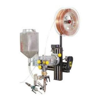
Example of the A6 SFE1C Straightener. Contact equipment, which consists of a contact tip, connector and flux tube. Slide (motor--driven). Motor and gearbox (A6 VEC). Flux hopper (1 l). Connection instructions for SAW and MIG/MAG welding appear from the system dia- gram on page 69. - Page 9 2. Connect the A6 welding heads as follows: SUBMERGED ARC WELDING (SAW) Connect the control cable (7) between the welding power source (8) and the A2--A6 Process Controller (PEH) (2). Connect the return cable (11) between the welding power source (8) and the work piece (9).
-
Page 10: Operation
OPERATION General General safety regulations for the handling of the equipment can be found on page 64. Read through before you start using the equipment! Select wire type and flux or shielding gas so that the weld material is as close as possible to the analysis of the base metal. - Page 11 Check that the feed roller (1) and contact jaw or contact tip (3) are of the correct dimension for the selected wire size. Pull the end of the wire through the straightener (2). For a wire diameter greater than 2 mm; straighten out 0.5 m of wire and feed it by hand down through the straightener.
- Page 12 Contact equipment for submerged- -arc welding For single wire 3.0 - - 4.0 mm. Light duty (D20) Use the straightener (3), connector (1) D20 with contact tip (2) (M12 thread). Tighten the contact tip (2) with a key in order to ensure that a good contact is achieved.
- Page 13 For twin wires 2 x 2.0 - - 3.0 Heavy Twin (D35) (Accessories) Use the straightener (3), connector (1) D35 with contact jaws (2). Fit the first contact jaw with the M5 bolts supplied, in the fixed connector (a). Fit the other contact jaw in the free half of the two--piece connector (b) under the bolt (8) and tighten down hard to ensure that a good contact is achieved between the contact jaws and the wire.
-
Page 14: Conversion Of A6 Sfe1 (Submerged Arc Welding) To Mig/Mag Welding
Contact equipment for MIG/MAG welding. For single wire 1.6 - - 2.5 mm (D35) Use the straightener (3), connector (1) D35 with contact tip (2) (M10 thread). Tighten the contact tip (2) with a key to ensure that a good contact is achieved. Fit the clamp (7) with guide tube (6) in the M12 hole on the standard straightener (3). -
Page 15: Maintenance
MAINTENANCE General NB! Before doing any kind of maintenance work, make sure the mains is discon- nected. For the maintenance of the A2--A6 Process Controller (PEH), see the instruction manual. Daily Clean flux and dirt off moving parts of the welding machine. Check that the contact tip and all electric cables are connected. -
Page 16: Fault Tracing
FAULT TRACING Equipment S Instruction manual for control box A2--A6 Process Controller. Operating manual for motor with gear A6 VEC, order no. 0443 393. Check that the power source is connected for the correct mains supply that all three phases are live (phase sequence is not important) that welding cables and connections are not damaged that the controls are correctly set that the mains supply is disconnected before starting repairs... -
Page 17: Accessories
0147 333 001 ORDERING OF SPARE PARTS Spare parts are ordered through your nearest ESAB representative, see back cover. When ordering spare parts, please state machine type and number as well as desig- nation and spare part number as shown in the spare parts list on page 207. - Page 18 ESAB subsidiaries and representative offices Europe NORWAY Asia/Pacific Representative offices AS ESAB AUSTRIA BULGARIA CHINA Larvik ESAB Ges.m.b.H ESAB Representative Office Shanghai ESAB A/P Tel: +47 33 12 10 00 Vienna- -Liesing Sofia Shanghai Fax: +47 33 11 52 03...
Need help?
Do you have a question about the A6 S Arc Master and is the answer not in the manual?
Questions and answers