
Related Manuals for ESAB Aristo U8


Summary of Contents for ESAB Aristo U8
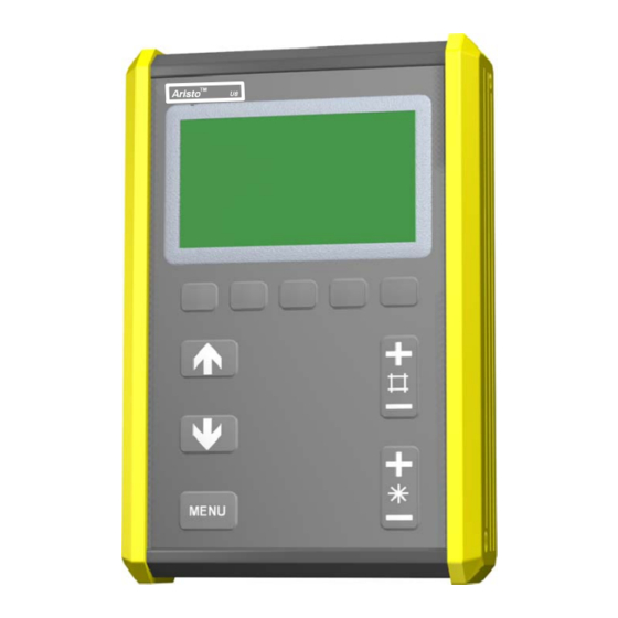
- Page 1 Aristot Instruction manual 0459 310 274 080115 Valid for program version 1.41, 1.50...
-
Page 2: Table Of Contents
1 INTRODUCTION ........... 1.1 Equipment . - Page 3 5 TIG WELDING ........... . . 5.1 Settings in the weld data setting menu .
- Page 4 ..........18.1 ESAB Logic Pump (Water lock) .
- Page 5 ORDERING NUMBER ..........ACCESSORIES .
-
Page 6: Introduction
U8 is supplied with a holder, 3 spacer screws and an English instruction manual. The instruction manuals and the spare parts list are available in other languages on the Internet at www.esab.com Under ”Products” and ”Welding & cutting equipment”, you will find a link to the page where you can both search for and download instructions and spare parts lists. - Page 7 AUXILIARY FUNCTIONS Move the cursor to the line for CONFIGURATION FILEMANAGER Press ENTER WELD DATA SETS CONFIGURATION QUALITY FUNCTIONS PRODUCTION STATISTICS ERROR LOG USER DEFINED SYNERGIC DATA LIMIT EDITOR QUIT ENTER AUXILIARY FUNCTIONS -- CONFIGURATION Press ENTER to call up a list of the languages LANGUAGE: ENGLISH...
-
Page 8: Display
Display ESAB Mig PROCESS: MIG/MAG METHOD: DIP / SPRAY WIRE TYPE: SHIELDING GAS: WIRE DIMENSION: 1.2 MM AUXILIARY FUNCTIONS FAST MEASURE MEMORY MODE ENTER The cursor The cursor in the controller appears as a shaded field around the text, which has the effect of turning the selected text white. -
Page 9: Keys
Keys You can use the arrow keys to move the cursor to different lines in the display. The menu key will always return you to the main menu. The plus/minus keys are used to increase (+) or decrease (--) the value of a setting. -
Page 10: Setting Fixed Options
1.5.2 Setting fixed options Certain settings are defined by selecting an option from a list. The list might look like this: MIG/MAG CARBON, ArcAir MIG SUPERPULSE Here the cursor is on the line for MIG/MAG. If you press the ENTER key now, you will select the MIG/MAG option. -
Page 11: Menus
During start--up, a start--up screen also appears containing information about which program version is being used. Main menu In the MAIN MENU you can ESAB Mig change weld process weld change weld process, weld method, wire type, etc. -
Page 12: Weld Data Setting Menu
2.1.2 Weld data setting menu In the WELD DATA WELD DATA SETTING SETTING MENU you can SETTING MENU you can change various weld parameters. The menu’s VOLTAGE: # 26.8 (+0.0) V appearance differs, WIRE SPEED: m/min depending on which weld INDUCTANCE: process you have selected. -
Page 13: Memory Functions Menu
2.1.4 Memory functions menu In the MEMORY MEMORY FUNCTIONS -- STORED DATA SETS FUNCTIONS MENU you FUNCTIONS MENU you can store, recall and delete various items of preset weld 1 2 5 11 12 data. Weld data settings can be stored in 255 different memory positions. -
Page 14: Menu Structure
Menu structure AUXILIARY FUNCTIONS MEASURE MEMORY FAST MODE STOP DATA COPY START DATA RECALL DELETE STORE *) This is the start image (measure image) that is shown when you switch on the machine. The sample image above is for MIG/MAG- -welding with synergic mode. AUXILIARY FUNC- auxiliary functions see page... -
Page 15: Mig/Mag Welding
MIG/MAG WELDING Main menu - - - - > Process The arc in MIG/MAG welding melts a filler wire (the electrode) that is continuously fed into the weld, with the molten zone being protected by a shielding gas. Pulsing is used to affect the transfer of the droplets from the arc so that it is stable and does not produce spray, even with low weld data. -
Page 16: Mig/Mag Welding With Pulsing
3.1.2 MIG/MAG welding with pulsing Settings Setting range In steps Values Synergic Adjust- - after reset depend- able in synergic Voltage 10 -- 50 0.25 (dis- synergic played to deviation one deci- ¦ 0 mal place) Wire speed ** 0.8 -- 25.0 m/min 0.1 m/min 5 m/min Pulse current ***... -
Page 17: Function Explanations For Settings
Function explanations for settings 3.2.1 Voltage Higher voltage increases the arc length and produces a hotter, wider weld pool. The voltage setting differs between synergy and non synergy modes. In synergy mode the voltage is set as a positive or negative offset from the synergic line of the voltage. -
Page 18: Background Current
It is also possible to order other packages of synergy lines, but these must be installed by an authorised ESAB service engineer. 3.2.13 Gas pre- -flow Gas pre--flow controls the time during which shielding gas flows before the arc is struck. -
Page 19: Creep Start
3.2.14 Creep start Creep starting feeds out the wire at 50% of the set speed until it makes electrical contact with the workpiece. With a hot start it is 50% of the hot start time. 3.2.15 Hot Start Hot start increases the wire feed speed and voltage for an adjustable time at the start of welding, thus reducing the risk of poor fusion at the beginning of the joint. -
Page 20: Pinch--Off Pulse
The final parameter values must always be equal to or lower than the set values for continuous welding. If the settings for continuous welding are lowered below the set final values they will also lower the final values. The final parameter values will not increase again if the setting for continuous welding is increased. -
Page 21: Settings In The Weld Data Setting Menu
Settings in the weld data setting menu Settings Setting range In steps Values Synergic Adjust- - after reset depend- able in synergic Current* 16 -- 500 A 128 A Synergic mode OFF or ON ON ** Arc force 0 -- 100% Min current factor 0 -- 100% *) Maximum current depending on which type of machine is used. -
Page 22: Settings In The Weld Data Setting Menu
Settings in the weld data setting menu 5.1.1 TIG welding without pulsing Settings Setting range In steps of: Values after reset HF / LiftArct HF or LiftArc LiftArc 2/4--stroke 2--stroke or 4--stroke 2--stroke Current* 4 -- 500 A 25 A Slope up time 0 -- 25 s 0.1 s... -
Page 23: Liftarc
5.2.2 LiftArc With LiftArct the arc is struck when the electrode is lifted from the workpiece. Striking the arc using the LiftArc function. Step 1: the electrode is touched on to the workpiece. Step 2: the trigger switch is pressed, and a low current starts to flow. Step 3: the welder lifts the electrode from the workpiece: the arc strikes, and the current rises automatically to the set value. -
Page 24: Current
In 4--stroke control mode, pressing the trigger switch starts gas pre--flow (if used) (1). At the end of the gas pre--flow time, the current rises to the pilot level (a few amperes), and the arc is struck. Releasing the trigger switch (2) increases the current to the set value (with slope up, if in use). -
Page 25: Background Time
5.2.9 Background time Time for background current, which, along with the time for pulse current, gives the pulse period. -- Background time is set in the weld data setting menu. Only applies for TIG welding with pulse. Current Background time Background current Pulse current Pulse time... -
Page 26: Other Function Explanations
Other function explanations 5.3.1 Gas purge The gas purge function is used when measuring the gas flow or to purge the gas hoses of any air and moisture before welding commences. Gas purging proceeds as long as the key is pressed down, and is conducted without current and wire feed being switched on. -
Page 27: Aristo Superpulse
Aristo SuperPulse Mig 4000i, Mig 4500i, Mig 5000i Main menu - - - - > Process MIG SUPERPULSE (Aristo SuperPulset) is used for improved control of the weld pool and the solidification process. The weld pool has time to solidify partially between each pulse. -
Page 28: Settings In The Weld Data Setting Menu
Settings in the weld data setting menu Settings for dip--/spray arc alternative pulsing see chapter 3.1.1 and 3.1.2. Settings Setting range In steps of: Values after Synergic Adjust- - reset depend- able in synergic Phase Primary or Primary secondary Phase weld time 0 -- 2.50 s 0,01 0.05 (secondary) - Page 29 Difference in wire feed speed n m/min Cycle time (s) The graphs for 15 m/min and 20 m/min respectively refer to the primary wire feed speed. The cycle time is the sum of the primary and secondary phase weld time. The difference between primary and secondary wire feed speed must not exceed the speed that is indicated by the graphs of the primary wire feed speed.
-
Page 30: Memory Management
Welding example B In this exemple we will weld a 6 mm plate with 1.2 mm aluminium wire and argon shielding gas. Make the following settings with the controller: Process MIG SUPERPULSE MIG SUPERPULSE Phase Primary Secondary Method Pulse Pulse Wire type Al Mg Al Mg... -
Page 31: Store
Store If the weld data memory is empty, the following screen appears in the display. MEMORY FUNCTIONS -- STORED DATA SETS We will now store a set of weld data. We will give it memory position 5. Press the STORE key. * NO STORED DATA SETS * STORE QUIT... -
Page 32: Delete
STORE IN DATA NO. 5 " DIP/SPRAY, Fe, CO2, 1.2 mm QUIT ENTER Return to the memory menu by pressing the QUIT key. NOTE! Every MIG SUPERPULS data take two memory positions. Delete In the memory menu you can delete one or more data sets. We are going to delete the data set that we stored in the previous example. -
Page 33: Recall
DELETE WELD DATA NO. 5 Press ENTER to confirm the deletion of data set number 5. " DIP/SPRAY, Fe, CO2, 1.2 mm QUIT ENTER Return to the memory menu by pressing the QUIT key. NOTE! If MIG SUPERPULSE is deleted, both of the memory positions 5 and 6 will be deleted. -
Page 34: Copy
The following text box appears briefly: RECALLED DATA SET NO. 5 Return to the memory menu by pressing the QUIT key. This icon in the measure image shows which memory position has been recalled. Copy This is how you copy the content of a weld data setting to a new memory position: MEMORY FUNCTIONS -- STORED DATA SETS Press the COPY key. -
Page 35: Auxiliary Functions
Weld data setting number 5 has now been copied to memory position 50. If memory position 50 is already taken, you are informed of this on the display. COPY WELD DATA NO. 5 TO NO. 50 " DIP/SPRAY, Fe, CO2, 1.2 mm QUIT ENTER Return to the memory menu by pressing the QUIT key. -
Page 36: Inserting A Compact Flash Card / Pc--Card
10.1 Inserting a compact flash card / PC- -card To enable you to use this function fully, you must first insert a compact flash card / PC--card (PCMCIA) into the controller. A card adapter is also required to enable the compact flash card and welding machine to work together. -
Page 37: Example: Creating A New Folder On A Memory Card
To save the quality data stored on the controller, do the same as for WeldData.awd, but highlight the file with the extension .aqd instead and press ENTER. You have then saved information on the last 100 welding cases. For a description of quality data, see the ”Quality functions”... -
Page 38: Changing The Name Of A File/Folder
Highlight DELETE and press ENTER. COPY DELETE RENAME The file/folder has now been deleted. A folder can only be deleted if it is empty, i.e. the files inside the folder must be deleted first. 10.5 Changing the name of a file/folder Highlight the file or folder to have its name changed and press ALT. -
Page 39: Quality Data Files Content
10.8 Quality data files content The quality data files look like this: The first block contains information on the welding equipment and the second block, the welds. Differing data on a single row is separated by a semicolon. Quotation marks are used to mark text, i.e. anything that is not to be translated (and processed), as numbers. -
Page 40: About The Welds
10.8.2 About the welds Review of the second block based on the column headings. Weld no. In the example above, data has been stored for four welds, which can be read out from the far left column, Weld no. A new row is created with a new Weld no. for each new weld. -
Page 41: Weld Data Sets
10.8.4 Explanation of digits in the ChangeStatus column: Neither the welding schedule, wire speed nor voltage have been changed since the end of the previous weld. Wire speed and/or voltage changed before welding started. Wire speed and/or voltage changed during welding. Wire speed and/or voltage changed before and during welding (1+2) New welding schedule requested during weld in progress. -
Page 42: Recalling Welding Data From A Memory Card
The entire welding data settings configuration saved in the welding data memory (utilised memory positions 1--255) is now saved on the compact flash card in the WeldData.awd file. The file is located in a folder called WData. WData is generated automatically when you insert a memory card. -
Page 43: Lock Code Mode
-- Code lock is enabled in the configuration menu. 12.1.1 Lock code mode In lock code mode you can enable/disable the lock function without deleting the existing lock code in case you disable the function. If no lock code is stored and you attempt to enable the code lock, the following screen appears, in which you can enter a new lock code. -
Page 44: Set / Change Lock Code
This brings you to the keyboard display, where you can type in the lock code. After each character press the PRESS KEY and confirm the lock code using the ENTER key. The following text box appears: UNIT UNLOCKED! If the lock code is incorrect, you will see an error message that gives the user the option of trying again or returning to the original menu, i.e. -
Page 45: Configuring A Digital Remote Control
12.2.2 Configuring a digital remote control Without remote control adapter When a CAN--bus remote control is connected, the configuration for DIGITAL OP is made automatic. With remote control adapter When using a digital remote control, specify which type of remote control is being used: If you move the cursor to the line for DIGITAL OPERATED and press ENTER, you will call up a list from which you can select an option. -
Page 46: Mig/Mag Defaults
12.2.4 Range of inputs You can set the control range for the potentiometer(s) to be used. You do this by using the plus/minus keys on the controller to define a minimum value and a maximum value. Note you can set different voltage limits in synergy and non synergy modes. The voltage setting in synergy is a deviation (plus or minus) of the synergy value. -
Page 47: Soft Keys Setup
-- Activation of 2--stroke performed in the measure image, configuration menu or with a soft key in the measure image. 4- -stroke There are 3 start and 2 stop positions for 4--stroke. This is start and stop position 1. When resetting position 1 is selected. See the chapter 12.3.4 ”4--stroke configuration”. - Page 48 Trigg weld data switch ON/OFF The selection you set for weld data switch before the soft key is activated applies with weld data switch ON. AT ARC OFF or ON. Weld data switch is off when weld data switch OFF is selected. The display image contains two columns: one for function and one for key number ASSOCIATE FUNCTIONS TO SOFT KEYS Function...
-
Page 49: Voltage Measurement For Dip
12.3.3 Voltage measurement for dip The voltage measurement options for dip welding are as follows: Peak value for pulse voltage (PULSE) The voltage is only measured during pulses and is filtered before the voltage value is displayed. Average voltage value (AVERAGE) The voltage is measured continuously and is filtered before the voltage value is displayed. -
Page 50: Mma Defaults
4- -stroke stop mode 1 Time controlled crater filling with the possibility of extending this, see the chapter 12.3.1 ”4--stroke” 2 Trigger--controlled crater fill time Gas flow Wire feed Welding ----------Crater filling-------- Press in the trigger (3), crater filling starts and expires. If the trigger is released (4) during crater fill time (crater fill time reduced) the welding stops. -
Page 51: General Defaults
12.5 General defaults Main menu - - - - > Auxiliary function menu - - - - > Configuration menu - - - - > General defaults 12.5.1 Fast mode soft keys The soft keys ”WELD DATA 1” – ”WELD DATA 4” are visible in the fast mode menu. These are configured as follows: FAST MODE SOFT KEYS Move the cursor to the line... -
Page 52: Auto Save Mode
12.5.4 Auto save mode When a weld data set has been recalled from a memory position in the weld data memory and you change the settings, the changes will be automatically saved in the memory position when you recall a new weld data set from memory. Saving weld data manually in a memory position blocks the next automatic save. -
Page 53: Quality Data Logging
12.5.6 Quality data logging To enable you to use this function, insert a compact flash card into the controller, see ”File manager”. chapter. Activating/deactivating logging of quality data CONFIGURATION -- GENERAL DEFAULTS Use the arrow keys to highlight QUALITY DATA FAST MODE SOFT BUTTONS LOG TO FILE and press DOUBLE START SOURCES:... -
Page 54: Multiple Wire Feeders
12.6 Multiple wire feeders Main menu - - - -> Auxiliary fuction menu - - - - > Configuration menu- - - - > Multiple wire feeders When connecting multiple wire feed units (maximum 4), use wire feed units without weld data unit, control panel M0. -
Page 55: Weld Data
12.6.1 Weld data Weld data is connected individually to each wire feeder. To connect weld data to a wire feeder, it must be active; when it is, you can recall data in the usual way, see chapter ”Memory management”, and make any necessary modifications. All of this will then be connected to the active wire feeder. -
Page 56: Saving Quality Data On A Compact Flash Card
You can select a particular weld by pressing the plus/minus keys when the cursor is on the line that shows the relevant weld number. In the same way, you can enter the length of the weld to obtain the heat input. 13.1 Saving quality data on a compact flash card To enable you to use this function, insert a compact flash card into the controller (see... -
Page 57: Production Statistics
PRODUCTION STATISTICS Main menu - - - -> Auxiliary function menu - - - -> Production statistics Production statistics are used to keep track of the total arc time, the total volume of material used and the number of welds since the last reset. They also keep track of the arc time and the amount of material used for the last weld. -
Page 58: Error Log
ERROR LOG Main menu - - - - > Auxiliary function menu - - - - > Error log Error monitoring codes are used to indicate that an error has occurred in the welding process. This is shown in the display with the aid of a pop--up menu, which appears for 2.5 seconds. -
Page 59: Error Code List
15.3 Error code list Error Description Controller Power Wire code source feeder Memory error EPROM Memory error RAM Memory error external RAM 5V power supply High DC intermediate voltage High temperature High primary current Mains power supply 1* Mains power supply 2* Mains power supply 3* Wire feed servo Communication error (warning) -
Page 60: Error Code Descriptions
15.4 Error code descriptions Error Description code Program memory error (EPROM) The program memory is damaged. This fault does not disable any functions. Action: Restart the machine. If the error persists, call a service engineer. Microprocessor RAM error The microprocessor cannot write/read to the internal memory. This fault does not disable any functions. - Page 61 Error Description code - -15V power supply, (power unit) The supply voltage is too high or too low. Action: Call a service engineer. +20V power supply, (wire feeder) The supply voltage is too high or too low. Action: Call a service engineer. +15VB power supply, (Mig 4500i) The supply voltage is too high or too low.
- Page 62 Error Description code Non- -permitted settings stored in RAM. Non--permitted values have been found during start--up. Deletes all data in the controller. Action: Turn off the mains power supply to reset the system. Reset the controller. The settings will be in English with MIG/MAG, DIP/SPRAY, Fe, CO2, 1.2 mm. If the error persists, call a service engineer.
-
Page 63: User- -Defined Synergic Data
Error Description code No gas flow Gas flow is less than 6 l/min. Unable to start. Action: Check the gas valve, hoses and connectors. Incompatible units Incorrect wire feed unit is connected. Start is prevented Action: Connect the correct wire feed unit. USER- -DEFINED SYNERGIC DATA Main menu - - - ->... -
Page 64: Pulsing
The following also applies: A higher weld data number must contain higher values for voltage and wire feed speed than the weld data number that precedes it. The weld parameters inductance, regulator type and hot start--voltage must have the same values in all four weld data numbers. Define the number of co--ordinates that are needed, and then proceed to chapter 16.2 ”Specifying the valid wire/gas combination”. -
Page 65: Creating User--Defined Wire/Gas Options
Select one of the options from the list and press ENTER. Ss (Stainless) Ss duplex Al Mg Al Si Metal cored Fe Rutile FCW Fe ↓ Make a selection for shielding gas in the same way, and press ENTER. Ar+20%CO2 Ar+2%O2 Ar+30%He+1%O2 Ar+2%CO2... -
Page 66: Deleting A User--Defined Synergic Line
The controller’s ”keyboard” is used as follows: Position the cursor over the desired keyboard character using the arrow keys. Press the soft key ”PRESS KEY”. Type in a full text string with a maximum 13 characters in this way. Position the cursor over and press the soft key ”PRESS KEY”, after which the user--defined, named option will appear in... -
Page 67: Other Information
OTHER INFORMATION 18.1 ESAB Logic Pump (Water lock) U8 works together with the ELP function on the wire feed unit/power source, see the Instruction Manual for the wire feed unit/power source for further information. -
Page 68: Wire And Gas Combinations
Wire and gas combinations MIG/MAG welding with DIP/SPRAY Wire type Shielding gas Wire diameter (mm) Low alloy or unalloyed wire 0.8 0.9 1.0 1.2 1.6* (Fe) Ar + 20% CO 0.8 0.9 1.0 1.2 1.6* Ar + 2% O 0.8 0.9 1.0 1.2 1.6* Ar + 5%O + 5% CO 0.8 1.0 1.2 1.6*... - Page 69 MIG/MAG welding with PULSE Wire type Shielding gas Wire diameter (mm) Low alloy or unalloyed wire Ar + 20% CO 0.8 0.9 1.0 1.2 1.6* (Fe) Ar + 2% O 0.8 0.9 1.0 1.2 1.6* Ar + 2% CO 0.8 1.0 1.2 1. 6* Ar + 5%O + 5% CO 0.8 0.9 1.0 1.2 1.6*...
- Page 70 0459 310 283 Instruction manual HU 0459 310 284 Instruction manual CZ 0459 310 990 Spare parts list Instruction manuals and the spare parts list are available on the Internet at www.esab.com - - 70 - - Edition 080115 bi09o11a...
- Page 71 Accessories Control cable (connectors included) 5 m ........0456 280 881 10 m .
- Page 72 ESAB subsidiaries and representative offices Europe Asia/Pacific Representative offices NORWAY AS ESAB AUSTRIA BULGARIA CHINA Larvik ESAB Ges.m.b.H ESAB Representative Office Shanghai ESAB A/P Tel: +47 33 12 10 00 Vienna- -Liesing Sofia Shanghai Fax: +47 33 11 52 03...
Need help?
Do you have a question about the Aristo U8 and is the answer not in the manual?
Questions and answers