Sign In
Upload
Download
Table of Contents
Contents
Add to my manuals
Delete from my manuals
Share
URL of this page:
HTML Link:
Bookmark this page
Add
Manual will be automatically added to "My Manuals"
Print this page
×
Bookmark added
×
Added to my manuals
Manuals
Brands
ESAB Manuals
Welding Accessories
Aristo MA4
Service manual
ESAB Aristo MA4 Service Manual
Hide thumbs
1
Table Of Contents
2
3
4
5
6
7
8
9
10
11
12
13
14
15
16
17
18
19
20
21
22
23
24
25
26
27
28
29
30
31
32
33
34
35
36
page
of
36
Go
/
36
Contents
Table of Contents
Bookmarks
Table of Contents
Table of Contents
Read this First
Introduction
Description of Operation
1AP1 Welding Data Board
1AP1:1 Power Supply
1AP1:2 Communication
1AP1:3 Fault Indication, Panel M2
1AP1:4 Settings, Panel M2
1AP1:5 Display, Panels MA4, MA6 and U6
1AP1:6 Settings, Panels MA4, MA6 and U6
1AP1 Component Positions
Fault Codes
Fault Log
Fault Indication on the M2 Control Panel
Fault Codes for the MA4, MA6 and U6 Panels
Summary of Fault Codes
Fault Code Descriptions, Control Panel
Service Instructions
What Is ESD
Service Aid
Exchange Circuit Boards
Instructions M2
Instructions Ma4
Introduction
Menus
Mig/Mag Welding
Mma Welding
INSTRUCTIONS MA6 and U6
Introduction
Menus
Menu Structure, Panel MA6
Menu Structure, Panel U6
Mig/Mag Welding
TIG WELDING, Panel U6
Mma Welding
Arc- -Air Gouging
General Functions
Remote Control Unit
Settings
Memory Management
Lock Code
Spare Parts
Notes
Advertisement
Quick Links
1
1Ap1 Welding Data Board
2
1Ap1:5 Display, Panels Ma4, Ma6 and U6
3
1Ap1:6 Settings, Panels Ma4, Ma6 and U6
4
Fault Codes
5
Fault Codes for the Ma4, Ma6 and U6 Panels
6
Menu Structure, Panel Ma6
7
Spare Parts
Download this manual
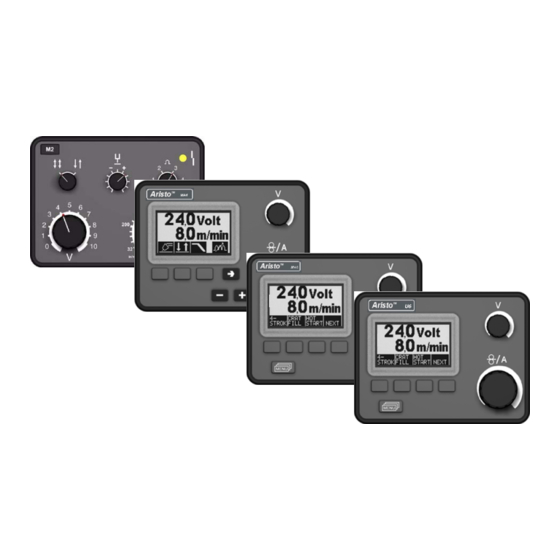
M2, MA4, MA6, U6
Aristo
t
Service manual
0740 800 152
061012
Table of
Contents
Previous
Page
Next
Page
1
2
3
4
5
Advertisement
Table of Contents
Need help?
Do you have a question about the Aristo MA4 and is the answer not in the manual?
Ask a question
Questions and answers
Related Manuals for ESAB Aristo MA4
Welding System ESAB Aristo U6 Instruction Manual
(56 pages)
Welding System ESAB Aristo U6 Instruction Manual
(48 pages)
Control Panel ESAB Aristo U6 Instruction Manual
(40 pages)
Welding Accessories ESAB Aristo U6 Service Manual
(28 pages)
Welding Accessories ESAB Aristo MA6 Service Manual
(36 pages)
Welding Accessories ESAB MT-400EHD Instructions For Use Manual
Mig welding gun with bayonet connector (20 pages)
Welding Accessories ESAB MT-200 Instructions For Use Manual
Mig welding gun with bayonet connector (20 pages)
Welding Accessories ESAB MXH 315 PP Instruction Manual
Welding torches (34 pages)
Welding Accessories ESAB FE MINI 200 Instruction Manual
Fume extraction torches (26 pages)
Welding Accessories ESAB SAVAGE A40 User Instructions
Welding helmet (100 pages)
Welding Accessories ESAB SAVAGE A40 User Instructions
Welding helmet (6 pages)
Welding Accessories ESAB Eye-Tech 9–13 User Instructions
(41 pages)
Welding Accessories ESAB SAVAGE A40 User Instructions
Welding helmet (179 pages)
Welding Accessories ESAB A6 S Arc Master Instruction Manual
(18 pages)
Welding Accessories ESAB A6 VEC Instruction Manual
(50 pages)
Welding Accessories ESAB ET 17 Instruction Manual
(158 pages)
This manual is also suitable for:
Aristo m2
Aristo ma6
Aristo u6
Table of Contents
Print
Rename the bookmark
Delete bookmark?
Delete from my manuals?
Login
Sign In
OR
Sign in with Facebook
Sign in with Google
Upload manual
Upload from disk
Upload from URL


Need help?
Do you have a question about the Aristo MA4 and is the answer not in the manual?
Questions and answers