Sign In
Upload
Download
Table of Contents
Contents
Add to my manuals
Delete from my manuals
Share
URL of this page:
HTML Link:
Bookmark this page
Add
Manual will be automatically added to "My Manuals"
Print this page
×
Bookmark added
×
Added to my manuals
Manuals
Brands
FULTON Manuals
Boiler
RB Series
Installation, operation and maintenance manual
FULTON RB Series Installation, Operation And Maintenance Manual
Gas/oil/dual fuel horizontal steam boilers
Hide thumbs
1
2
Table Of Contents
3
4
5
6
7
8
9
10
11
12
13
14
15
16
17
18
19
20
21
22
23
24
25
26
27
28
29
30
31
32
33
34
35
36
37
38
39
40
41
42
43
44
45
46
47
48
49
50
51
52
53
54
55
56
57
58
59
60
61
62
63
64
65
66
67
68
69
70
71
72
73
74
page
of
74
Go
/
74
Contents
Table of Contents
Troubleshooting
Bookmarks
Table of Contents
Table of Contents
Section 1 - Introduction
General
Product Overview
Technical Data
Section 2 - Installation
General
Pre-Installation
Siting
Ventilation
Major Components
Flue Outlet
Blowdown Valves
Main Boiler Blowdown Valve
Water Level Gauge Set (Sight Glass)
Main Steam Valve
Steam Safety Valve
Water Supply
Fuel Supply
Gas Supply
Oil Supply
Dual Fuel Supply
Electrical Requirements
Cleaning Steam Lines and Pressure Vessels
Section 3 - Operation
General
Controls
System Controls
Steam Pressure Controls
Adjusting Steam Pressure Controls
Boiler Control Panel
Burner Control Panel
Filling the Boiler-All Models
Draining the Boiler
Boiler Start-Up (from Cold)-All Models
Boiler Start-Up Following Short Term Shut-Down
Boiler Shut-Down
Short Term Shut-Down (Hours)
Medium Term Shut-Down (Days)
Long Term Shut-Down (Weeks)
Internal Economiser (if Fitted)
Section 4 - Maintenance
Boiler Platform (if Fitted)
Visual Checks
Burner Flame Sensor Test
Water Level and Low Water Safety Control Procedures
Feedwater Pump Test
1St Low Water Level Check
2Nd Low Water Level Check
Evaporation Check
Blowdown Procedures
Main Boiler Blowdown
Water Level Gauge (Sight Glass) Blowdown
Boiler Internal Inspection
Fitting New Gaskets to Boiler Inspection Holes
Important Information
Fitting Procedure
Front Access Door
Front Access Door Adjustment and Seal
Front Access Door Insulation
Feedwater Disperser
Service Inspection of Welded Joints (UK Only)
Schedule of Operator Tests and Checks
Daily
Weekly in Addition
Three Monthly - in Addition
Six Monthly -I N Addition
Annually in Addition
Troubleshooting - Boiler
Troubleshooting - Feedwater Pump
Appendix A - Ti Sheets
RB Dimensions & Specification
RBC Dimensions & Specification
RB Probe Lengths
RBC Probe Lengths
Recommended Water Conditions
Boiler Water Sample Cooler
Water Level Probes
Auto TDS Blowdown Systems
Advertisement
Quick Links
1
Technical Data
2
General
3
Product Overview
4
Rb Dimensions & Specification
Download this manual
INSTALLATION, OPERATION AND MAINTENANCE MANUAL
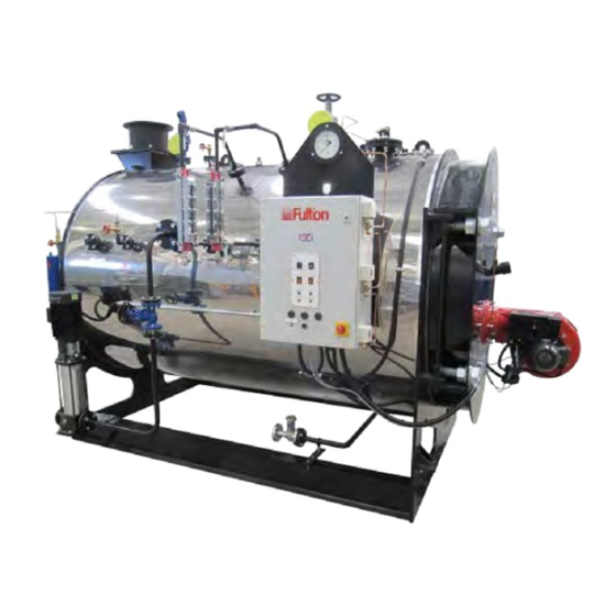
RB / RBC Series
Gas / Oil / Dual Fuel Horizontal Steam Boilers
This manual must be available to the boiler operator at all times.
RB-RBC-IOMM-2015-1
Table of
Contents
Previous
Page
Next
Page
1
2
3
4
5
Advertisement
Table of Contents
Troubleshooting
Troubleshooting - boiler
54
Troubleshooting - feedwater pump
56
Need help?
Do you have a question about the RB Series and is the answer not in the manual?
Ask a question
Questions and answers
Related Manuals for FULTON RB Series
Boiler FULTON Reliance 500 Installation And Operation Manual
(60 pages)
Boiler FULTON RBC Series Installation, Operation And Maintenance Manual
Gas/oil/dual fuel horizontal steam boilers (74 pages)
Boiler FULTON FB-L 012 Installation Operation And Care
Fulton electric boilers (steam models) (46 pages)
Boiler FULTON FB-L 150 Installation Operation And Care
Fulton electric boilers (steam models) (46 pages)
Boiler FULTON FB-L 300 Installation Operation And Care
Fulton electric boilers (steam models) (46 pages)
Boiler FULTON 60E Operator, Service & Parts Manual
E series gas fired steam boilers (44 pages)
Boiler FULTON Caliber Installation And Operation Manual
High efficiency hydronic boilers 300,000 - 850,000 btu/hr (56 pages)
Boiler FULTON ICW6 - 60 HP Installation And Operation Manual
Vertical tubeless design gas/oil-fired hot water boilers (52 pages)
Boiler FULTON VMP-W 40 -150 HP Installation And Operation Manual
Vertical multi-port hot water boilers (52 pages)
Boiler FULTON FHE-250 Installation, Operation & Maintenance Manual
Gas fired condensing boiler 250 kw (78 pages)
Boiler FULTON PHW 300 Installation And Operation Manual
Gas pulse combustion hydronic heating boiler (84 pages)
Boiler FULTON FB-S series Installation, Operation & Maintenance Manual
(31 pages)
Boiler FULTON EDR-1000 Installation And Operation Manual
Endura series (edr) condensing hydronic boilers 1,000,000 - 2,000,000 btu/hr (68 pages)
Boiler FULTON J Series Installation, Operation And Maintenance Manual
Gas fired steam boiler (including optional fully modulating burner) (72 pages)
Boiler FULTON VMP40 Installation, Operation And Maintenance Manual
Gas fired steam boilers (69 pages)
Boiler FULTON Endura+ Series Installation And Operation Manual
Condensing hydronic boilers (82 pages)
This manual is also suitable for:
Rbc series
Rbc750
Rbc1000
Rbc1250
Rbc1500
Rbc1850
...
Show all
Rbc2100
Rbc2500
Ti-135-rb
Rbc3000
Rb1600
Rb2600
Rb3400
Ti-109-rbcrb
Rbc600
Table of Contents
Save PDF
Print
Rename the bookmark
Delete bookmark?
Delete from my manuals?
Login
Sign In
OR
Sign in with Facebook
Sign in with Google
Upload manual
Upload from disk
Upload from URL


Need help?
Do you have a question about the RB Series and is the answer not in the manual?
Questions and answers