FULTON J Series Installation, Operation And Maintenance Manual
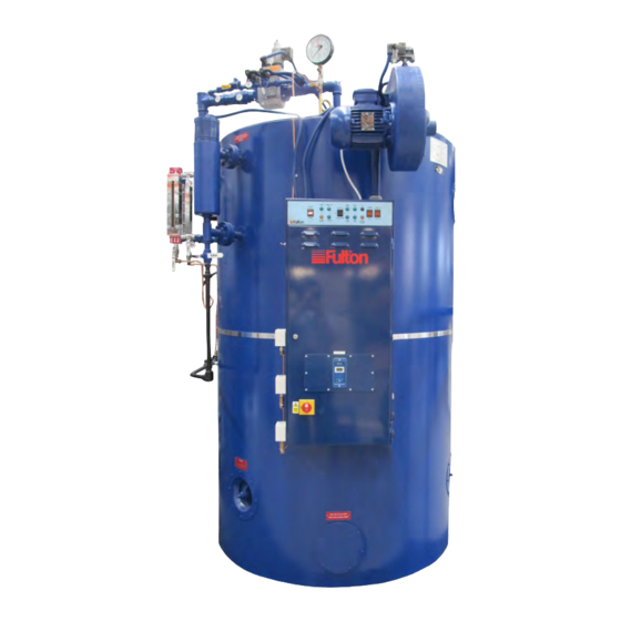
Gas fired steam boiler (including optional fully modulating burner)
Hide thumbs
Also See for J Series:

Related Manuals for FULTON J Series


Summary of Contents for FULTON J Series
- Page 1 INSTALLATION, OPERATION AND MAINTENANCE MANUAL J Series (UK) Gas Fired Steam Boiler (including optional fully modulating burner) This manual must be available to the boiler operator at all times. JGASUK-IOMM-2015-2...
- Page 2 Fulton Ltd Page II JGASUK-IOMM-2015-2...
-
Page 3: Table Of Contents
TABLE OF CONTENTS Fulton Ltd 4.10 Internal Inspection SECTION 1 - INTRODUCTION 4.11 Schedule of Operator Tests and Checks General 4.11.1 Daily Technical Data 4.11.2 Weekly-in addition SECTION 2 - INSTALLATION 4.11.3 Monthly-in addition General 4.11.4 Three Monthly-in addition Siting 4.11.5... - Page 4 The Pressure System Safety Regulations 2000 Fulton boilers fall within the scope of the Pressure Systems Examination Scheme. Regular inspections are therefore required by a competent person.
- Page 5 DANGER FROM INCOMPLETE COMBUSTION you do not understand. Obtain a service manual from The importance of correct burner adjustment to achieve Fulton Ltd or call a Fulton service engineer. low emissions, safe, clean and efficient combustion is paramount. Poor combustion, where unburnt gas forms carbon monoxide is both a health hazard, and...
- Page 6 Fulton Ltd Pressure gauge Monobloc gas valve Air pressure switch Low water level probes Water column containing Air intake water level probes Water level gauge (sight glass) Boiler control panel Water level gauge blowdown valves Control box Water column door lock...
-
Page 7: Section 1 - Introduction
TECHNICAL DATA For a full specification refer to Appendix A - TI-117-J Series Dimensions & Specification. CAUTION WATER SOFTENER and CHEMICAL TREATMENT The chemicals required to operate the water softeners and chemical treatment plants CAN BE SUPPLIED by Fulton. - Page 8 Fulton Ltd Pressure gauge Air pressure switch Low water level probes Water column Air intake containing water containing main air level probes control Water level gauge (sight glass) Boiler control panel Water level gauge blowdown valves AZL burner control Water column...
-
Page 9: Section 2 - Installation
The boiler house should be sufficiently sized to allow easy and safe access to all parts of the boiler for operational and maintenance purposes. Reference should be made to Appendix A - TI-117-J Series Dimensions & Specification to ascertain the relevant dimensions and weights, special note should be taken of the required vertical clearance required for maintenance. -
Page 10: Ventilation
Note: Do not store chemicals such as perclorethylene in the boiler house, the fumes may damage the boiler and flue and cause the burner to lock out on flame failure. Note: see Appendix A - TI-117-J Series Dimensions & Specification for low and high level values. FLUE OUTLET The boiler is supplied with a stainless steel flue spigot that should be inserted into the flue outlet in the back of the boiler and secured with the three angle clips supplied loose in the trim box. - Page 11 Fulton Ltd Cowl Pipe safety valve to a safe area, using unions and drain as required. Standard boiler trim D = Diameter of flue supplied with boiler Feedwater isolation ball valve Steam supply H = 1.5 X D Flue Vent to...
-
Page 12: Water Supply
Note: If the boiler is to be operated with little or no condensate return, consideration should be given to pre-heating the feedwater. If in doubt consult Fulton Ltd. Note: The feedwater inlet connection on some boilers is located on the left hand side of the boiler below the sight glass assembly. -
Page 13: Blowdown Valve
Regulations exist covering such items and care must be taken to ensure compliance with these regulations. If in doubt regarding blowdown arrangements, consult Fulton Ltd. Note: 8J - 15J main blowdown connection is via a branch pipe. Note: 20J - 60J main blowdown connection is integral, via a boiler mounted flange. -
Page 14: Main Steam Valve
INSTALLATION - 2 Fulton Ltd MAIN STEAM VALVE The main steam stop valve should be inserted in the steam line approximately 305 mm from the top of the boiler. STEAM SAFETY VALVES Safety valves are factory fitted and pre-set, they MUST NOT be adjusted. The discharge outlet should be piped to a safe discharge point and the piping so arranged that any condensate trapped in the pipework will drain away from the valve. -
Page 15: Gas Valve With Pilot Gas Line
Unless otherwise specified, the alarms supplied will be mains voltage models. Unless otherwise specified all models are supplied with burner motors and feedwater pump motors arranged for operation on a three phase supply. The power ratings and requirements are given in Appendix A - TI-117-J Series Dimensions & Specification. 2.12 STEAM PRESSURE GAUGE The steam pressure gauge assembly should be assembled in accordance with Figure. 8 using a suitable sealant on all joints. - Page 16 INSTALLATION - 2 Fulton Ltd Pressure gauge Air proving Gas train with switch 360° rotation Burner scroll Feedwater stop valve Low level water Secondary air probes control TDS system Steam safety valve Feedwater line Feedwater check valve Note: Boiler illustrated is fitted with optional Self Monitoring Controls.
-
Page 17: Commissioning The Boiler
INSTALLATION - 2 Fulton Ltd 2.13 COMMISSIONING THE BOILER It is essential that the commissioning procedures listed below are carried out by a Fulton service engineer who will have the necessary experience and testing equipment to ensure that the installation is not only correct, but is operating safely and at optimum efficiency. Flue Commissioning Prior to initial firing of the boiler, the flue must be checked for leaks. - Page 18 INSTALLATION - 2 Fulton Ltd 4. Ensure that all wiring connections are correct and that all terminal screws are tight. 5. A barometric type draught stabiliser, if fitted in the flue, should be set for a draught of - 0.025 mbar to - 0.05 mbar of water column pressure with the burner off. 6. Open all the valves in the feedwater line.
- Page 19 INSTALLATION - 2 Fulton Ltd If the pressure control is fitted with a differential scale: 1. Set the main scale pressure to the maximum pressure required (system pressure). Do not exceed the boiler operating pressure. 2. Set the differential scale to it’s minimum pressure. If the pressure control has a fixed differential, i.e. no adjustable differential scale, set the main scale to the maximum pressure required.
-
Page 20: Setting Burner Controls-Low/High Fire (40J-60J)
INSTALLATION - 2 Fulton Ltd 2.13.2 SETTING THE BURNER CONTROLS LOW/HIGH FIRE (40J - 60J) The correct setting for low fire/high fire operation is made by making adjustments to the two stage solenoid valve and the low fire steam pressure switch. 1. Isolate the main gas valve by closing the valve in the gas input line. 2. Screw the pilot gas governor fully down (governor open). -
Page 21: Multi Bloc Gas Valves
INSTALLATION - 2 Fulton Ltd 2.14 MULTI BLOC GAS VALVES Main gas line isolating valve Pilot line Pilot line Pilot line Main gas valve ball valve governor gas valves assembly Figure. 13 - 40J - 60J Gas Valve (non modulating burner) - Page 22 INSTALLATION - 2 Fulton Ltd Note: See attached manufacturers leaflets. Output pressure controller adjusting screw Operating indicator Hydraulic Brake Adjustable pressure Main gas flow adjustment switch Test point connection Test point connection downstream of Valve 1 Gas output flange Gas input filter cover Test point connection Test point connection...
- Page 23 INSTALLATION - 2 Fulton Ltd Hydraulic brake Main gas flow adjustment Output pressure controller adjusting High fire solenoid screw Operating pressure indicators Low fire flow adjustment Input gas test point Adjustable pressure switch Test point 1 downstream (internal leak test) Gas input mounting flange location Test point 2 downstream Test point 1upstream Figure.
-
Page 24: Cleaning Steam Lines And Pressure Vessels
INSTALLATION - 2 Fulton Ltd 2.15 CLEANING STEAM LINES AND PRESSURE VESSELS During the first week of boiler operation, clean all oil and dirt from the boiler, the steam line and condensate return line. 1. Disconnect the condensate return pipe adjacent to the condensate return tank. 2. Direct the returns to a floor drain or other safe discharge point and make safe. 3. Leave in this position for one week to allow all impurities to flush through. 4. Drain the boiler completely each day. 5. After the week is completed, drain and flush the condensate return tank, removing all installation sediment. -
Page 25: Section 3 - Operation
Fulton Ltd SECTION 3 - OPERATION CAUTION The following instructions are given for the guidance of the operator in the use of the Fulton steam boiler. No responsibility can be accepted by Fulton Ltd if these instructions are ignored. GENERAL... - Page 26 OPERATION - 3 Fulton Ltd Burner Programmer. This is the main control in the panel box. The programmer in conjunction with a sensing device ‘supervises’ the ignition sequence, proves the flame is satisfactory and finally ‘monitors’ the established flame. Should any fault occur, either during the ignition sequence or during normal running, the programmer will immediately go to ‘lockout’ and the Multi-bloc gas valve will be closed. Air Pressure Switch. Mounted on the burner scroll, this switch is operated by the pressure of air entering the burner through the throat of the scroll. Lack of air, or insufficient pressure, will...
-
Page 27: Indicator Lights
OPERATION - 3 Fulton Ltd INDICATOR LIGHTS Indicator lights are fitted to the control panel as an additional aid to the operator. The meaning and operating sequence of these lights is as follows: CAUTION The control circuit live light is derived from a single phase. It is possible that with the control phase down or a defective bulb the other phases could be live. Always isolate the supply before investigating any fault. -
Page 28: Filling The Boiler-All Models
OPERATION - 3 Fulton Ltd FILLING THE BOILER ALL MODELS Carry out the following procedure on the initial start up of the boiler and on every subsequent occasion when restarting the boiler after a shut down: a) Ensure the main steam stop valve is OPEN. -
Page 29: Starting The Burner-All Models
OPERATION - 3 Fulton Ltd STARTING THE BURNER ALL MODELS 1. Press the control switch to PUMP AND BOILER position, the Low Water audible alarm will sound, the Low Water Reset and Low Water alarm lights will illuminate. 2. Press the Low Water Reset switch for two seconds maximum. The alarms will stop, and the alarm lights will extinguish. - Page 30 MAINTENANCE - 4 Fulton Ltd Removing/replacing water level probe Feedwater dip pipe Pressure gauge Monobloc gas valve Air pressure switch Low water level probes Water column containing Air intake water level probes Water level gauge (sight glass) Boiler control panel...
-
Page 31: Section 4 - Maintenance
MAINTENANCE - 4 Fulton Ltd SECTION 4 - MAINTENANCE CAUTION It is vitally important that the instructions given in this manual are strictly adhered to. Failure to carry out the daily, weekly, monthly and six monthly checks could result in a drastic reduction in the life expectancy of the boiler. -
Page 32: 1St Low Water Level Check
MAINTENANCE - 4 Fulton Ltd 2. Lower the water level by opening the main boiler blowdown valve. 3. Verify that the pump starts to run when the water level reaches the Pump On level. 4. Close the main boiler blowdown valve. -
Page 33: 2Nd Low Water Level Check
MAINTENANCE - 4 Fulton Ltd 4.2.3 2ND LOW WATER LEVEL CHECK 1. Ensure that the boiler is firing, the feedwater pump is not running and that the water level is between Pump On and Pump Off. 2. Switch off the pump using the Pump Interrupt/Pump Run switch. 3. Allow the water level to lower by natural evaporation to the 1st Low Water level. -
Page 34: Main Blowdown
Keep the boiler, water level gauge (sight glass), water column and interconnecting pipework free from sludge and scale build-up by blowing down in the following manner: Note: Where a boiler is operating continuously at steam pressure, advice should be sought from Fulton Service Department regarding the appropriate blowdown procedure. -
Page 35: Water Level Gauge Blowdown
On completion of the blowdown procedure ensure that all isolation valves are OPEN and all blowdown valves are CLOSED. Note: Where a boiler is operating continuously at steam pressure, advice should be taken from Fulton Ltd as to the appropriate blowdown procedure. -
Page 36: Evaporation Checks
MAINTENANCE - 4 Fulton Ltd EVAPORATION CHECKS With the boiler running under normal load conditions, and the pump stopped having just completed a refill cycle: a) Ensure that the boiler water level is correct. b) Switch the pump OFF at the pump interrupt/pump run switch. -
Page 37: Draining The Boiler
MAINTENANCE - 4 Fulton Ltd DRAINING THE BOILER CAUTION Your local regulations could state boiler water above 43 °C must not be discharged into the drain. ALWAYS check your local regulations. Boilers with manual blowdown valves 1. Ensure the boiler is cold. -
Page 38: Long Term Shut Down
MAINTENANCE - 4 Fulton Ltd LONG TERM SHUT DOWN To store the boiler in a corrosion-free situation there are three practical solutions: 1. Fully flood the boiler to exclude as much air as possible. 2. Drain the boiler completely. Remove all hand hole and manhole doors. Open all gas/oil side access doors. -
Page 39: Schedule Of Operator Tests And Checks
4.11 SCHEDULE OF OPERATOR TESTS AND CHECKS The following schedule is the advice of Fulton Ltd. The frequency of tests and checks may vary according to site risk assessment and/or specific requirements of the country/territory that the boiler is installed in. Failure to maintain the boiler adequately may void the Fulton warranty. -
Page 40: Daily
13. Clean the water level gauges (sight glasses). If any leakage is evident, the gasket needs replacing. 14. Clean any water traps and strainers fitted in the feedwater line. Check feedwater and boiler water quality against the values given in Appendix A - TI-139- Recommended Water Conditions. Note: Use only genuine Fulton replacement parts. Page 34 JGASUK-IOMM-2015-2... -
Page 41: Three Monthly-In Addition
IN ADDITION It should be noted that after a Fulton boiler has been in operation for several months, pieces of burned metal will be found in the space at the bottom of the boiler. These pieces of metal are the remains of a light gauge metal form which was used during manufacture for the forming of the boiler insulation. This is normal and does not affect the efficiency or the life of the boiler in any... - Page 42 25. Remove the water level gauge (sight glass) and water column. Rod through the top connections of both to ensure that the holes in the baffle plates (approx. 6 mm dia.) inside the boiler are not obstructed. 26. Check the burner combustion to ensure that excess air and carbon monoxide values are within normal limits (see combustion values in Appendix A - TI-117-J Series Dimensions & Specification). 27. Check the condition of the gas valve filter (if fitted), renew as required. Cleaning...
-
Page 43: Annually-In Addition
MAINTENANCE - 4 Fulton Ltd Figure. 32 - Burner Plate Figure. 33 - Burner Assembly 4.11.6 ANNUALLY IN ADDITION 28. Fulton Ltd recommend replacement of all threaded stub pipes on the boiler OR to your inspectors satisfaction. Page 37 JGASUK-IOMM-2015-2... -
Page 44: Troubleshooting-Boiler
MAINTENANCE - 4 Fulton Ltd 4.12.1 TROUBLESHOOTING BOILER Problem Cause Remedy 1. Power Supply Check fuse or circuit breaker. Ignition Failure Reset or Replace as required. 2. Ignition Electrodes Check for cracks in porcelain,if found replace the electrode. Check electrodes for carbon build-up. - Page 45 Check CO and O levels. 5. Draft Check draft with a gauge. Readings will vary between installations, if in doubt consult Fulton for a draft value for your system. 6. Dirty Flue Check flue for carbon build-up or blockage. Clean the flue. 7. Negative Room Pressure Ensure there are no exhaust fans running in the boiler room.
- Page 46 3. Scale buildup or lime deposits. Consult Fulton or call a water treatment specialist. 4. Too much compound (water Dump contents of the return tank and flush the treatment over dose). system. Test the water.
-
Page 47: Troubleshooting-Feedwater Pump
MAINTENANCE - 4 Fulton Ltd 4.12.2 TROUBLESHOOTING FEEDWATER PUMP Problem Cause Remedy 1. Supply failure. Connect the electricity supply. FEEDWATER PUMP Pump will not run 2. Fuses/Circuit Breakers are blown. Replace fuses/Circuit Breakers. 3. Motor contactor overload has Reactivate the motor protection. - Page 48 MAINTENANCE - 4 Fulton Ltd 4.12.2 TROUBLESHOOTING FEEDWATER PUMP Problem Cause Remedy 1. Leakage in suction pipe. Repair the suction pipe. Pump runs backwards when 2. Foot or non-return valve is Repair the foot or non-return valve. switched off. defective.
- Page 49 MAINTENANCE - 4 Fulton Ltd 4.12.3 TROUBLESHOOTING BURNER CONTROL UNIT-LFL 1 (SIEMENS) Symptom and Cause Remedy identification symbol 1. No Power Check all fuses/circuit breakers No Start Check for correct wiring. 2. External Interlocks Check all external interlocks are made.
- Page 50 MAINTENANCE - 4 Fulton Ltd 4.12.3 TROUBLESHOOTING BURNER CONTROL UNIT-LFL 1 (SIEMENS) Symptom and Cause Remedy identification symbol 1. No main flame Check supply to main valve(s) Lockout Check functionality of main valve(s). Check gas pressure at burner. Check air pressure at burner.
-
Page 51: Maintenance Log
MAINTENANCE - 4 Fulton Ltd 4.13 MAINTENANCE LOG This log should be completed regularly as a record of boiler maintenance. Date Action Remarks Sig. Page 45 JGASUK-IOMM-2015-2... - Page 52 MAINTENANCE - 4 Fulton Ltd Page 46 JGASUK-IOMM-2015-2...
-
Page 53: Appendix A - Ti Sheets
Fulton Ltd APPENDIX A - TI SHEETS The Fulton boiler manual refers to a number of Fulton TI sheets. These TI sheets can be found in this Appendix. Note: The TI sheets in this appendix can be updated/replaced without revising the manuals issue number. To check you have the most up to date TI sheet, please check the downloads section on the Fulton website (www.fulton.co.uk/support/downloads) or consult Fulton Ltd. - Page 54 APPENDIX - A Fulton Ltd Page 48 JGASUK-IOMM-2015-2...
- Page 55 APPENDIX - A Fulton Ltd Technical Information Sheet No. 117 Issue 8 J Series Dimensions & Specification Dimensions 360° MODEL: J SERIES 6J/8J/10J 50J/60J Minimum Clearance* 2300 2400 2600 2800 3100 Overall Width 1030 1250 1440 1655 Overall Depth 1025...
- Page 56 APPENDIX - A Fulton Ltd Specification TI-117-J-DS-2015-8 MODEL: J SERIES UNIT CE marked to PED, EMC & LVD, constructed to BS2790 as standard (other code specifications available). General Steam Output F & A 100 °C kg/h kW Rating Operating Pressure ** barg 10.34...
- Page 57 Note: ‘350’ Sight Glass Probe Lengths Probe Lengths High Level Pump Off 1st Low Water 405 Pump On Probe Lengths - J Series 2nd Low Water 430 measurements in mm Pump OFF Pump ON 1st Low Water 2nd Low Water...
- Page 58 APPENDIX - A Fulton Ltd Page 52 JGASUK-IOMM-2015-2...
- Page 59 APPENDIX - A Fulton Ltd Technical Information Sheet No. 139 Issue 1 J Series & Electric Steam Boilers Recommended Water Conditions IMPORTANT It is very important that a strict water management program is followed to ensure trouble free boiler operation.
- Page 60 Fulton Ltd Page 54 JGASUK-IOMM-2015-2...
-
Page 61: Appendix B - Water Level Probe Info
APPENDIX - B Fulton Ltd APPENDIX B - WATER LEVEL PROBE INFO IMPORTANT Terminal and securing nuts must not be adjusted. Only Angle Rajah are to be used to connect wire to the probes. The Terminal & Securing Nuts are tightened to a specified torque during manufacture which causes the PTFE Insulation to seal against the probe body. Therefore these nuts must not be adjusted because the seal will be broken which may cause the probe to leak (see Figure. - Page 62 Fulton Ltd Page 56 JGASUK-IOMM-2015-2...
-
Page 63: Appendix C - Motorised High/Low Control
APPENDIX - C Fulton Ltd APPENDIX C - MOTORISED HIGH/LOW CONTROL GENERAL The Fulton motorised high/low control is designed to improve the efficiency of the boiler by switching the firing rate from high fire (when there is low steam pressure in the boiler) to low fire (when the boiler reaches a high steam pressure). The systems major components comprises of; two stage gas valves, motorised air damper unit and two stage steam pressure switches. -
Page 64: Additional Controls
APPENDIX - C Fulton Ltd ADDITIONAL CONTROLS Low Fire Hold Switch - Used to maintain the boiler in the low fire mode during commissioning. COMMISSIONING Commissioning should be carried out by a qualified Fulton Service Engineer. To achieve the ideal combustion efficiency and gas input rates, a gas flow rate meter is required to measure the fuel input to the boiler. 1.4.1 FUEL INPUT RATES Model Low Fire 11.6 11.6 23.2 29.0 34.8 /min. 10.3 13.7 17.1 20.5... -
Page 65: Setup Procedure
APPENDIX - C Fulton Ltd 1.4.3 SETUP PROCEDURE 1. Set the cams on the air damper motor to the initial position. Start the boiler and wait until the motor and gas valve have driven to high fire. Adjust the main (primary) air gate to achieve the best combustion with the least buffeting in the furnace. - Page 66 Fulton Ltd Page 60 JGASUK-IOMM-2015-2...
-
Page 67: Appendix D - Spirax High Integrity Level
APPENDIX - D Fulton Ltd APPENDIX D - SPIRAX HIGH INTEGRITY LEVEL CONTROLS DAILY TESTS The daily testing of boiler water level controls is a mandatory requirement as defined in the Health & Safety Executive Guidance Note BG01, Arrangements 2 and 3. The level of supervision is dependent upon the type of level controls (limiters) fitted. Boilers fitted with self monitoring high integrity controls (limiters) should be tested daily by a qualified boiler attendant, but may be supervised during the silent hours and weekends by a competent person trained to respond to an alarm. Daily testing of the controls is required which can be by simulation, with a weekly test by interrupting the feedwater pump and lowering the water by evaporation. -
Page 68: Weekly Test-In Addition
APPENDIX - D Fulton Ltd WEEKLY TEST IN ADDITION 1.2.1 1ST LOW WATER WEEKLY IN ADDITION With the burner firing: 1. Switch the Pump Interrupt switch to the Pump Interrupt position. 2. By evaporation lower the water level in the boiler until the 1st Low Water alarm sounds and the Low Water indicator lamp illuminates, and the burner shuts down. -
Page 69: Appendix E - Automatic Tds Blowdown
APPENDIX - E Fulton Ltd APPENDIX E - AUTOMATIC TDS BLOWDOWN SYSTEM GENERAL The purpose of an Automatic, Total Dissolved Solids (TDS) Control Blowdown System, is to control the TDS level within the boiler around a set point. It is not a substitute for the main boiler blowdown, which must be used to control suspended solids, and prevent the build-up of sludge in the bottom of the boiler. - Page 70 When purchasing an Automatic TDS Control Blowdown System from Fulton, the equipment would normally be supplied with the controller wired and fitted to the boiler control panel, with all the other parts supplied loose for piping and wiring on site by others, unless agreed otherwise in our order acknowledgement.
- Page 71 G U A R A N T E E On the Fulton Boiler Pressure Vessel Fulton Ltd will repair or replace EXW factory any Fulton pressure vessel which within five (5) years of the date of delivery is found to be defective in workmanship, or material, provided this equipment is operated and maintained by the buyer for the purpose for which it was designed and in accordance with the manufacturer’s handbook.
- Page 72 JGASUK-IOMM-2015-2 Fulton Ltd 5 Fernhurst Road Fishponds Bristol BS5 7FG England Telephone: +44 (0) 117 972 3322 Fax: +44 (0) 117 972 3358 Email: sales@fulton.co.uk FM 28400...
Need help?
Do you have a question about the J Series and is the answer not in the manual?
Questions and answers
I want to buy boiler