
Related Manuals for FULTON FHE-250


Summary of Contents for FULTON FHE-250
-
Page 1: Condensing Boiler
Fulton Ltd INSTALLATION, OPERATION & MAINTENANCE MANUAL FHE-250 Gas Fired Condensing Boiler 250 kW This Manual must be available to the boiler operator at all times. FHE-250 MANUAL 09 2014 ISSUE 2... - Page 2 The Pressure System Safety Regulations 2000 Fulton Boilers fall within the scope of the Pressure Systems Examination Scheme. Regular inspections are therefore required by a ‘Competent Person’. The scope of the examination and the actual intervals between examinations is at the discretion of the competent person.
-
Page 3: Table Of Contents
- Boiler Test Fire 3.8.1 Name Plates and Packaging Label - Disabling the Boiler 3.8.2 - Changing the Temperature Setpoint for DHW 3.8.3 Electrical Diagrams (Supplied Separately) - Changing the Temperature Setpoint for CH 3.8.4 FHE-250 MANUAL 09 2014 ISSUE 2... - Page 4 Do not try to do repairs or any other maintenance work you HYDRAULIC TEST - RISK OF BRITTLE FRACTURE do not understand. Obtain a Service Manual from Fulton or Hydraulic testing requires specialist equipment and is call a Fulton Service Engineer.
- Page 5 General Arrangement with Panels Removed Typical Gas Train Flue Gas Conditions Boiler Hydraulic Resistance Boiler Communication Cables Electrical Terminals 3-13 Disconnected Jumper Inserted Jumper Between Terminals 19 and 20 LCD Glass Layout Push-button Layout Boiler Dimensions Name Plates FHE-250 MANUAL 09 2014 ISSUE 2...
-
Page 6: General Arrangement
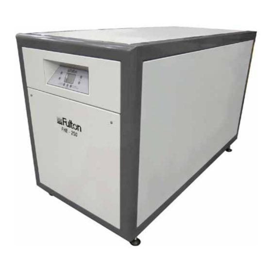
Boiler Control Panel Adjustable Feet FIG.1 GENERAL ARRANGEMENT FHE-250 MANUAL 09 2014 ISSUE 2... -
Page 7: Introduction
The boilers are fully automatically controlled, floor standing and efficient condensing appliances. The FHE-250 comprises of a single module capable of delivering 250 kW. Up to 12 FHE-250 modules can be cascaded (for simplicity, only 250-1000 kW models are shown in this manual), being stacked either vertically or horizontally. -
Page 8: Optional Extras
Water and Gas Header Assembly - Packaged Water and Gas Header Assembly c/w Valves - Packaged Flue Header Kit Note: Please contact Fulton Ltd for further details of all optional extras. SAFETY Current Gas Safety (Installation and Use) Regulations or rules in force. -
Page 9: Safe Handling
1.4.1 SAFE HANDLING The FHE-250 may require 2 or more operatives to move it to its installation site, and when moving into its installation location. Manoeuvring the boiler will include the use of a pallet truck or forklift and may involve pushing and pulling. -
Page 10: General Arrangement With Panels Removed
Heat Exchanger Automatic Air Vent Return Pipe Flow Pipe Condensate Pipe Venturi Valve Electrical Plate FIG. 2 GENERAL ARRANGEMENT WITH PANELS REMOVED Page 4 FHE-250 MANUAL 09 2014 ISSUE 2... -
Page 11: Installation
SECTION 2 - INSTALLATION GENERAL The installation of the FHE-250 Hot Water Boiler should be carried out by competent personnel in accordance with all relevant safety regulations. It is the responsibility of the installer to ensure that these regulations are complied with. -
Page 12: Water Circulation System
When sizing pumps, reference should be made to hydraulic resistances given in Section 2.18, which shows the boiler resistance against flow rates, to achieve the required temperature differential. Flow rate using a 20°C temperature differential is 3.0 l/s (10.7 m³/hr) for each FHE-250 boiler/module. -
Page 13: Water Piping Installation
(water inlet) connection to the boiler and piped to a drain. 9. Before installing a FHE-250 boiler into a hydronic loop, be sure that the system piping and any other components of the system are clean and free of debris and any foreign matter. The hydronic system should be completely flushed prior to installing the boiler itself. -
Page 14: Water Treatment
Section 5.4 - Recommended Water Conditions. WARNING The application of any other treatment to this product other than those recommended by Fulton Ltd may render the guarantee of Fulton Ltd invalid. 1. It is most important that the correct concentration of the water treatment products is maintained in accordance with the manufacturers’... -
Page 15: Eliminating System Air
Ventilation should also be considered to ensure ambient temperatures do not exceed designed recommendations. Further guidance is provided in IGEM/UP/2 (Institution of Gas Engineers and Managers-Installation pipework on industrial and commercial premises. Communication number 1729). Page 9 FHE-250 MANUAL 09 2014 ISSUE 2... -
Page 16: Gas Connection
The gas supply pipe terminates in a 28 mm copper pipe connection on each 250 model. Common gas supply pipe sizes for connection to multiple boiler modules are available on request from Fulton. 1. A minimum working gas pressure of 6.5 mbar must be available at the boiler inlet with the boiler firing. -
Page 17: Typical Gas Train
Modulating Gas Valve Isolating Valve Inlet to Modulating Gas Valve FIG. 3 TYPICAL GAS TRAIN Page 11 FHE-250 MANUAL 09 2014 ISSUE 2... -
Page 18: Sealed System Requirements
0.35 bar (35 kPa) of the safety valve setting. Other British Standards applicable to commercial sealed systems are: BS. 6880: Part 2 BS. 1212 BS. 6281: Part 1 BS. 6282: Part 1 BS. 6283: Part 4 Page 12 FHE-250 MANUAL 09 2014 ISSUE 2... -
Page 19: Ventilation
2551 3826.5 5102 Note: Where a boiler installation is to operate in summer months (e.g. DHW), additional ventilation requirements are stated within BS6644 if operating for more than 50% of the time. Page 13 FHE-250 MANUAL 09 2014 ISSUE 2... -
Page 20: Common Air Intake And Exhaust Venting Of
COMMON AIR INTAkE AND ExHAUST VENTING OF MULTIPLE BOILERS Combining multiple FHE-250 boilers into a common flue or duct for combustion air supply, exhaust, or both is only permitted on a case by case basis and must be accomplished with an engineered solution. -
Page 21: Exhaust Venting Terminations (Flues)
4. Terminations must be adequately weatherproofed. WARNING Assure all electrical connections are powered down prior to attempting replacement or service of electrical components or connections of the boiler. Page 15 FHE-250 MANUAL 09 2014 ISSUE 2... -
Page 22: Horizontal Exhaust Vent Termination
Fulton cannot be responsible for the effects such adverse conditions may have on the operation of the boilers. It is important to locate the exhaust duct in such a way that it does not become blocked due to snow, ice, and other natural or man-made obstructions. -
Page 23: Flue Installation
All joints or connections in the flue system must be impervious to condensate leakage. Low points in the flue system should be drained using pipe of material resistant to condensate corrosion. All drains in the flue should incorporate a water trap. Page 17 FHE-250 MANUAL 09 2014 ISSUE 2... -
Page 24: Flue Gas Conditions
For further details of the boiler set-up and commissioning, refer to section 3 of this manual. Flue Gas Constituents Item Carbon Dioxide (CO 9.5 ± 2.5 Carbon Monoxide (CO) 0.0075 ± 0.0075 Page 18 FHE-250 MANUAL 09 2014 ISSUE 2... -
Page 25: Condensate Drain
Each header system will be individually tailored to specific site/installation requirements. This is an optional extra, as detailed in Section 1.3, please contact Fulton for further details/designs. Page 19... -
Page 26: Electrical Supply
The point of isolation from the mains should be readily accessible and adjacent to the boiler. 2.18 HYDRAULIC RESISTANCE The hydraulic resistance through each FHE-250 module is 441 mbar (44.12 kPa) at full duty conditions, with a 20°C temperature differential between inlet (return) and outlet (flow). Pressure Drop (kPa) Flow Rate (L/s) 4.31... -
Page 27: Electrical Connections
Section 2.19.2 of this manual. Note. The circuit protective device, isolation switch and wiring must be sized in accordance with the total load of both the boiler and module pumps. Page 21 FHE-250 MANUAL 09 2014 ISSUE 2... -
Page 28: Boiler Communication Cables
The figure below shows the wire connections between the boilers in a cascade system. * Link Terminal 19 and 20 aster Slave 1 Slave 3 Slave 2 Boiler Boiler Boiler Boiler FIG. 6 BOILER COMMUNICATION CABLES Page 22 FHE-250 MANUAL 09 2014 ISSUE 2... -
Page 29: Terminal Connections For External Wiring
Fig. 7 shows electrical Terminal plugs 3-13 disconnected, while other terminals are electrically connected. Note that it is possible to remove the plugs, but not necessary for isolation. Fig. 9 shows a jumper inserted between Terminal 19 and 20. Page 23 FHE-250 MANUAL 09 2014 ISSUE 2... -
Page 30: Electrical Terminals 3-13 Disconnected
FIG. 7 ELECTRICAL TERMINALS 3-13 DISCONNECTED FIG. 8 JUMPER Inserted jumper FIG. 9 INSERTED JUMPER BETWEEN TERMINALS 19 AND 20 Page 24 FHE-250 MANUAL 09 2014 ISSUE 2... -
Page 31: Operation
SECTION 3 - OPERATION GENERAL The following instructions are given for the guidance of the operator in the use of the FHE-250 boiler and to provide adequate information to ensure that the boiler is used safely and without risk to health. -
Page 32: Commissioning The Boiler
It is essential that the commissioning procedures listed below are carried out either by a Fulton Service Engineer or by an authorised professional who will have the necessary experience and testing equipment to ensure that the installation is not only correct, but is operating safely and at optimum efficiency. -
Page 33: Test Of Ignition Safety System
1. Remove the cover plate from the switch. At high fire turn the adjustment on the switch counter clockwise (reducing the switch set-point to below the 9 mbar factory setting) until the boiler shuts down. Error code: E77. 2. Reset the switch to the factory setting of 9 mbar. Page 27 FHE-250 MANUAL 09 2014 ISSUE 2... -
Page 34: Normal Operation Of The Boiler
Adjust the firing rate as explained in the Local Test procedure above. d) Press and hold the “Test Mode” and “Confirm” buttons for 3 seconds to exit the Cascade Test mode. Page 28 FHE-250 MANUAL 09 2014 ISSUE 2... -
Page 35: Disabling The Boiler
In the case of one installed boiler, the temperature sensor can also be the cascade sensor. If there is no cascade sensor installed, then the boiler will modulate according to the water flow temperature sensor -this is an integral part of the boiler, factory fitted as standard. Page 29 FHE-250 MANUAL 09 2014 ISSUE 2... -
Page 36: Auto Detection
The boiler now enters suspend mode. Only frost protection is active. Refer to Section 2.6 for details of Frost Protection operation. 3.9.4 STARTING THE BOILER AFTER PROLONGED SHUTDOWN Perform initial start up procedures as described in this manual. Page 30 FHE-250 MANUAL 09 2014 ISSUE 2... -
Page 37: Display Operation
3.11 SYMBOLS ON THE LCD The FHE-250 is equipped with an LCD display capable of showing four full 7-segment digits and a set of additional icons showing information about the current state and operating mode of the device. Four 7-segment digits and alternatively partially implemented fifth digit are used for displaying numeric values and some letter indication. - Page 38 Detected slave DSP device in chain below Various functions -mainly answer button indicator On, when information is related to MAXSYS1 Detected master DSP device in chain above Not used yet On, when information is related to MAXSYS0 Page 32 FHE-250 MANUAL 09 2014 ISSUE 2...
-
Page 39: Push-Buttons
LCD- second screen for next 2 seconds: seg1 to seg4 : Displayed DSP software version number Buttons- no activity Note: After 2 seconds of showing the second screen, the boiler is switched to Standby mode. Page 33 FHE-250 MANUAL 09 2014 ISSUE 2... -
Page 40: Standby Mode On Master Dsp
Blinking when lockout error is displayed Blinking when error is related to MAXSYS0, or local device at position of MAXSYS0 Blinking when error is related to MAXSYS1, or local device at position of MAXSYS1 Page 34 FHE-250 MANUAL 09 2014 ISSUE 2... -
Page 41: Standby Mode On Slave Dsp
Indication of flame on local boiler Button Press: Function: D for 3 sec. Start of Auto Detection procedure B for 3 sec. Enter Local installer mode A for 3 sec. Enter Local test mode Page 35 FHE-250 MANUAL 09 2014 ISSUE 2... -
Page 42: Suspend Mode
D (autorepeat) Decrement setpoint value E (autorepeat) Increment setpoint value Briefly B Write setpoint value if modified and exit Note: After 10 seconds of keyboard inactivity, mode exits without updating the setpoint value. Page 36 FHE-250 MANUAL 09 2014 ISSUE 2... -
Page 43: Auto Detection Mode
Exit cascade test mode D (autorepeat) Decrement power demand E (autorepeat) Increment power demand Briefly F Set power demand to 0% (absolute minimum). Briefly G Set power demand to 100% (absolute maximum). Page 37 FHE-250 MANUAL 09 2014 ISSUE 2... -
Page 44: Local Test Mode
Set power demand to 0% (absolute minimum). Briefly G Set power demand to 100% (absolute maximum). Note: MAXSYS0 refers to a unit with LCD display and MAXSYS1 refers to a unit without display. Page 38 FHE-250 MANUAL 09 2014 ISSUE 2... -
Page 45: Local Installer Mode
P16 Total burners on Count of burners running P17 Total displays Total count of boiler modules Note: MAXSYS0 refers to a unit with LCD display and MAXSYS1 refers to a unit without display. Page 39 FHE-250 MANUAL 09 2014 ISSUE 2... -
Page 46: History Mode
Note: When the mode is invoked, indicates burner selection. User interface is switched to Index selection after 3 seconds or on demand. Index starts from number 0. After 1 second index is replaced by related error code. Page 40 FHE-250 MANUAL 09 2014 ISSUE 2... -
Page 47: Installer+ Mode
F (autorepeat) Decrement parameter value G (autorepeat) Increment parameter value Note: After each exit of Installer+ mode, the parameter load request is sent to all DSPs in the chain. This takes approx 15 seconds to complete. Page 41 FHE-250 MANUAL 09 2014 ISSUE 2... - Page 48 P39 Cascade frost off level [°C -or -°F] level to trigger frost protection on cascade sensor off P40 Cascade switch delay [sec] time to P41 DSP PI loop period [sec] period of PI calculation/integration step in DSP Page 42 FHE-250 MANUAL 09 2014 ISSUE 2...
-
Page 49: Maintenance
Maintenance on Gas appliances should only be carried out by competent, trained personnel who are ‘Gas Safe’ registered in the UK, and who have the necessary equipment to check combustion. If any fault is found during these operations contact your Fulton representative. Make the following checks for correct operation. -
Page 50: Partial Isolation Of Boilers In Cascade Systems
1. Remove the lower front panel of any boilers requiring changes, to access the necessary electrical terminals. 2. After any changes on boiler setup always perform an Auto Detection procedure as detailed in Section 3.8.7 of this manual. Page 44 FHE-250 MANUAL 09 2014 ISSUE 2... - Page 51 Ensure Terminal 20 is connected and Terminal 19 is disconnected on the last working boiler. * For details of terminal disconnection and jumper insertion, refer to Figs 7, 8 & 9 on page 24 of this manual Page 45 FHE-250 MANUAL 09 2014 ISSUE 2...
-
Page 52: Servicing Schedule
Fulton Ltd does not accept any liability resulting from the use of unauthorised parts or the repair and servicing of appliances not carried out in accordance with the Company’s recommendations and specifications. -
Page 53: Daily
9. Check flue gas temperature at outlet. If there is a temperature increase over previous readings, the probable cause is soot or water-scale build-up on the tubes. Consult Fulton immediately if there is a concern. 10. Test low gas pressure switch utilising the procedure in Section 3.6. -
Page 54: Annual
INSPECT HEATING SYSTEM FOR OTHER PROBLEMS 1. Perform combustion analysis and adjust if necessary. 2. Leak test gas valves. Leak Test must be performed only by qualified personnel, who have been trained in this procedure by Fulton. Page 48 FHE-250 MANUAL 09 2014 ISSUE 2... -
Page 55: Procedure For Removing/Cleaning The Burner
& yellow cable with a spade connector, labelled “earth” from the connector next to the ignition electrode • white 6-pin connector block, with wiring labelled “FLAP X3” from the flapper block connector 8. Undo the four nuts holding the flapper-mounting plate to the heat exchanger. Page 49 FHE-250 MANUAL 09 2014 ISSUE 2... -
Page 56: Procedure For Cleaning The Heat Exchanger
15. Use a soft, clean cloth to remove accumulated contaminants from the sight glass. 16. Before re-installing the burner, check the cleanliness of the heat exchanger and the condition of the combustion chamber. If corrosion or leaks are noticed, contact Fulton. 17. Reverse removal steps for reinstallation of the burner assembly. -
Page 57: Gas Valve Adjustment
2 to 7 if necessary. 9. Seal adjustment screw cap with tamper proof paint. 10. If the required CO level cannot be obtained with a CO/CO ratio below 0.004 then contact Fulton. Page 51 FHE-250 MANUAL 09 2014 ISSUE 2... -
Page 58: After All Repairs And Maintenance
Recommend that a contract for this work should be made with the regional gas authority or a Gas Safe Registered Engineer. In IE servicing work must be carried out by a competent person. Page 52 FHE-250 MANUAL 09 2014 ISSUE 2... -
Page 59: Error Codes And Troubleshooting
4.13 ERROR CODES AND TROUBLESHOOTING Error codes can be divided into 2 groups: 1. Lock-out error codes 2. Blocking error codes Page 53 FHE-250 MANUAL 09 2014 ISSUE 2... - Page 60 Page 54 FHE-250 MANUAL 09 2014 ISSUE 2...
- Page 61 Page 55 FHE-250 MANUAL 09 2014 ISSUE 2...
- Page 62 Page 56 FHE-250 MANUAL 09 2014 ISSUE 2...
- Page 63 Page 57 FHE-250 MANUAL 09 2014 ISSUE 2...
- Page 64 Page 58 FHE-250 MANUAL 09 2014 ISSUE 2...
- Page 65 Page 59 FHE-250 MANUAL 09 2014 ISSUE 2...
- Page 66 Page 60 FHE-250 MANUAL 09 2014 ISSUE 2...
- Page 67 Page 61 FHE-250 MANUAL 09 2014 ISSUE 2...
-
Page 68: Maintenance Log
4.14 MAINTENANCE LOG This log should be completed regularly as a record of boiler maintenance. Date Action Remarks Sig. Page 62 FHE-250 MANUAL 09 2014 ISSUE 2... - Page 69 This log should be completed regularly as a record of boiler maintenance. Date Action Remarks Sig. Page 63 FHE-250 MANUAL 09 2014 ISSUE 2...
- Page 70 Page 64 FHE-250 MANUAL 09 2014 ISSUE 2...
-
Page 71: General Data
Return Pipe Distance From Edge Condensate Pipe Height Condensate Pipe Distance From Edge Note: Dimensions are for one FHE-250 model, further models (if being cascaded) would be stacked vertically or horizontally. Adjust dimensions, according to number of models being cascaded. Dimensions mm Dimensions are approximate and only intended as a guide to aid installation. -
Page 72: Boiler Specification
BOILER SPECIFICATION Up to 12 FHE-250 models can be cascaded, allowing a total output of 3000 kW. For simplicity, 250 - 1000 kW models are shown below, more details on request. MODEL: FHE UNIT 1000 The FHE-250 has been designed and manufactured to the following standards:... -
Page 73: Seasonal Efficiencies
HM Government Non-Domestic Building Services Compliance Guide Method 94.2% Gross Efficiency : "A" Rated and above 86% - 90% 82% - 86% 78% - 82% 74% - 78% 70% - 74% Below Page 67 FHE-250 MANUAL 09 2014 ISSUE 2... -
Page 74: Recommended Water Conditions
Less than 5 mg/kg None Silica Less than 180 mg/kg, in the form of SiO mg/kg = Milligrams per Kilogram CaCO = Calcium Carbonate = Silicon Dioxide For practical purposes mg/kg = ppm Page 68 FHE-250 MANUAL 09 2014 ISSUE 2... -
Page 75: Name Plates
NAME PLATES FIG. 13 NAME PLATES Page 69 FHE-250 MANUAL 09 2014 ISSUE 2... - Page 76 Gas category: Gas type: Country of destination: FR, DE, BE, LU, PL, RO Gas category: r, I Gas type: G25 & G231 Country of destination: Gas category: Gas type: G25, G26 & G27 Page 70 FHE-250 MANUAL 09 2014 ISSUE 2...
- Page 77 On the Fulton Boiler Pressure Vessel Fulton Ltd will repair or replace EXW Bristol factory any parts which within two (2) years of the date of delivery is found to be defective in workmanship, or material, provided this equipment is operated and maintained by the buyer for the purpose for which it was designed and in accordance with the Manufacturer’s Handbook.
- Page 78 Fulton Ltd 5 Fernhurst Road Fishponds Bristol BS5 7FG England Telephone: +44 (0) 117 972 3322 Fax: +44 (0) 117 972 3358 Email: sales@fulton.com FHE-250 MANUAL 09 2014 ISSUE 2...
Need help?
Do you have a question about the FHE-250 and is the answer not in the manual?
Questions and answers