Table of Contents
Advertisement
Quick Links
Advertisement
Table of Contents

Related Manuals for DARAY SL200 Series


Summary of Contents for DARAY SL200 Series
-
Page 3: Table Of Contents
Installation - Ceiling mount Installation - Wall mount Assembly - Mobile mount Installation – Fit the jib-joint cover Installation – Fit the light-head 9 SPARE PARTS RETURNS POLICY WARRANTY Warranty Registration Tel: 0844 375 9000 Fax: 0333 321 0973 email: info@daray.com url: www.daray.com... -
Page 4: General Description
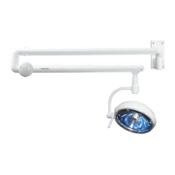
1. GENERAL DESCRIPTION The DARAY Illumin8 SL200 is a powerful minor-surgery light which is available in wall, ceiling or mobile versions. The SL200 differs from its predecessor in having variable intensity and a more robust method of mounting the light-head. -
Page 5: Dimensions/Range Of Movement
3. DIMENSIONS/RANGE OF MOVEMENT MOBILE MODEL... -
Page 6: Wall/Ceiling Model
WALL/CEILING MODEL (1) - Page 7 WALL/CEILING MODEL (2)
-
Page 8: Operation
4. OPERATION WALL/CEILING MODELS The SL200 wall and ceiling models are intended to be powered by a switched fused spur. The fuse should be rated at 5A. Alternatively provide another form of fused isolation. Installation of the supplied variable intensity controller is optional. Connect the SL200 to the mains and turn on at switched fused spur. -
Page 9: Battery Back-Up Module
BATTERY BACK-UP MODULE Cover screw Catch Battery low Lamp Power indicator switch switch Intensity Battery load controller indicator The optional battery back-up module restores power if normal mains power is interrupted or impaired. It also has the advantage of the addition of a light intensity control. To operate, turn the power switch ( ) on, turn the lamp POWER SW. -
Page 10: Lamp Replacement
Holding a replacement lamp by its plastic packaging, insert the wire connectors into the lamp holder. CAUTION: use only LB4059 replacement lamps from DARAY. These are special lamps and the use of any other type would seriously impair the performance of your light. -
Page 11: Fuse Replacement (Mobile Only)
6. FUSE REPLACEMENT CAUTION: fuses normally blow for a reason. Investigate likely faults before changing fuses. CAUTION: isolate the unit from the mains before accessing the fuses. SL200 MOBILE Both the live and neutral conductors are fused. The fuses are contained in a holder which is located on the side of the control box. -
Page 12: Maintenance
7. MAINTENANCE Cleaning and disinfection. WARNING: Do not use strong chemical cleaning agents such as ‘Dettox’ to sterilise the light. Do not use any abrasive materials to clean the light. CAUTION the light is not waterproof, so do not use excessive cleaning fluid amounts. Suitably protect hands. -
Page 13: Adjustment Of Arm To Prevent Drift
Operation Suggested Intervals On wall-mounted units, lift the arm so Six monthly its spigot is almost clear of the bush in the wall-mount plate and re-lubricate if required. On ceiling mount units, support the arm Six monthly and remove the 3 screws retaining the adaptor into the down-tube. -
Page 14: Installation/Assembly
8. INSTALLATION/ASSEMBLY CAUTION: this product must be earthed. Installation - Ceiling Mount Check you have the following items: Ceiling-mount plate assembly and cover Down-tube Kit of fittings D10522 Limited-rotation device D10524 Light-head and suspension arm Power supply module Determine where to mount light: Determine where to mount light from the positioning and ceiling-load forces diagrams, below: WARNING: please note that this information is provided for guidance only and that a... - Page 15 Fitting the ceiling plate Remove the clamp bolts, safety bolt/nylon insert nut and the clamp. Keep these parts in a safe place for use later. Fix the plate to the ceiling with bolts, screws or studs and nuts through the centre of each jack bolt.
- Page 16 Fitting the Down-tube A 1 metre length of down-tube is included with all ceiling mount kits, and must be securely fitted in accordance with these instructions. The down-tube should be cut to length on-site to suit the particular ceiling height and application.
- Page 17 NOTE: For conventional ceilings fit the cover, holding it in place with the retaining band from the fitting kit. Install the primary arm To ensure the smooth rotation of the arm, it is essential that the primary arm spigot is lightly lubricated before assembly.
- Page 18 Join the connector from the primary arm to the connector from the down-tube. Fit the supplied bungs. Make sure to sit the joined connectors inside the bung before fitting to prevent the cable from being damaged. Fit the jib-joint cover (see p.22). Fit the light-head (see p.23).
- Page 19 Wiring the SL200C SL200C wiring diagram The variable intensity control module should be mounted on a wall at a convenient position for the user. Provide a suitable, earthed electrical supply to the variable intensity control module via a switched, fused spur. Run a 1.5mm twin and earth cable to the ceiling plate 230V terminal block.
-
Page 20: Installation - Wall Mount
Installation - Wall Mount Check you have the following items: Wall-mount plate Light-head on suspension arm Power supply module To prevent damage in transit, the arm assembly is packed and delivered with the spigot in the ceiling-mount configuration. For wall mounting, turn the primary arm through 180 degrees, as follows: 180°... - Page 21 Fit the power-supply module directly under the wall plate. Remove the rear plate from the power-supply module by slackening the screw in each of the 4 corners. To ensure the smooth rotation of the arm, lightly grease the spigot on the primary arm with the silicone grease provided. Slide the spigot into the bracket on the wall-mount plate, feeding the low- voltage cable from the primary arm through the top of the power-supply module.
-
Page 22: Assembly - Mobile Mount
Assembly - Mobile Mount Fit the lower section of the up-stand to the base. Mate the locating peg on the lower up- stand section and its associated hole on the base. Refer to the 'peel-off' assembly marks as shown. - Page 23 Fit the upper section of the up-stand to the lower section of the up-stand with the screw and shake-proof washer using the hex wrench provided. Wrap flex around the cable holders Warning Only move the light using its handle. Fit the jib-joint cover (see p.23). Fit the light-head (see p.24).
-
Page 24: Installation - Fit The Jib-Joint Cover
Installation - Fit the jib-joint cover Locating key ‘CUT-OUT’ in aluminium casting Covers are marked 'L' and 'R' on their inside faces as viewed from the end of arm. Engage the slider, with its 'T' mark uppermost, into the groove inside the cover. Slider Fixing hole... -
Page 25: Installation - Fit The Light-Head
Installation - Fitting the light-head Connect the light-head connector to the connector in the arm Apply a little grease to the light-head spigot and insert it into the arm, being careful not to trap the cable/connector. Supporting the light-head in one hand, tighten the locking grub-screw with the hex key provided. -
Page 26: Spare Parts
9 SPARE PARTS CAUTION: Use only genuine DARAY replacement lamps as other types may seriously impair the optical performance of the product. ITEM NO PART NAME TYPE PART NO Replacement Lamp 24V, 100W LB4059 Fuse 1A 20mm D10873... -
Page 27: Returns Policy
If you send us goods that do not qualify for return, you will invalidate your claim to any refund, and you will be obliged to compensate DARAY Ltd for the cost of return postage and any other reasonable costs incurred processing the goods. - Page 28 • Failure to use or install the product in accordance with the manufacturer’s instructions. 5. Nothing in this warranty shall have the effect of restricting or excluding the liability of DARAY in respect of: a) Death and personal injury caused by the negligence of DARAY, or for fraud;...
- Page 32 Marquis Drive Moira Derbyshire DE12 6EJ Tel: 0844 375 9000 Fax: 0333 321 0973 info@daray.co.uk www.daray.co.uk...
Need help?
Do you have a question about the SL200 Series and is the answer not in the manual?
Questions and answers