
Related Manuals for DARAY SL700 Series


Summary of Contents for DARAY SL700 Series
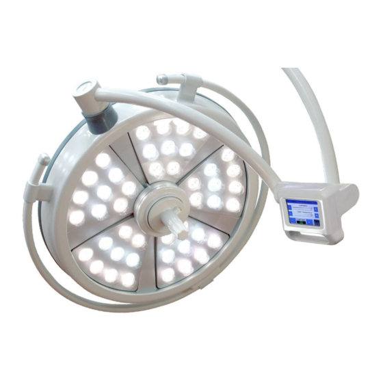
- Page 1 SL700 Series LED Operating Theatre Light System Including optional SL / camera Operating & Installation Manual QAM.SL700L.0219.10...
- Page 2 Page 1 of 39...
-
Page 3: Table Of Contents
Contents 1. Introduction ..............3 1.1 Supported Lights............3 1.2 Lighting Specification ..........4 1.3 Pre-Installation Responsibilities and component packing list ..4 1.4 Packing List ............. 4 1.5 Essential adjustment information ........6 2. Operation Guide Section ..........7 2.1 Range of Motion ............ -
Page 4: Introduction
Thank you for choosing a Daray SL700 Series Operating Theatre Light. The SL700 Series of lights are specifically designed to meet the demanding needs of today’s medical department whilst providing the finest quality design with superior performance, reliability and value. This manual has been provided to give detailed descriptions covering the performance, operation and safety information of the device. -
Page 5: Lighting Specification
1.3 Pre-Installation Responsibilities and component packing list This document is a guide to the steps that need to be performed to correctly install the SL700 Series Operating Theatre Light System. However, the work required to be performed is the responsibility of the owner or designated contractor/s. - Page 6 1 Wall Mount Cover The ceiling mounted edition of the SL700 series lights has a recommended fixing point of 3 metres from the floor; the minimum height is 2.7m and maximum of 3.3m. Anything over this height or systems using multiple satellites, will require a customised length of downtube.
-
Page 7: Essential Adjustment Information
1.5 Essential adjustment information PLEASE NOTE: THE SUSPENSION ARM IS SENT OUT IN A LOCKED HEIGHT POSITION For a detailed description of all these adjustments, please refer to page 34 of this user manual. Rotation arm Rotation arms are adjusted using tension points located on the central arm boss. -
Page 8: Operation Guide Section
2. Operation Guide Section Page 7 of 39... -
Page 9: Range Of Motion
2.1 Range of Motion The full range of motion between the SL700 series varies dependent on mounting. This is an image depicting the range of motion on a double ceiling mount fitting. Page 8 of 39... -
Page 10: Pre-Start Checks
Please check (when applicable) that the head and arms are without visible damage, and all LED’s are present in the head. Please note, the SL700 series may take a few seconds to power on fully and illuminate, please be patient when first turning on the light. -
Page 11: Adjusting The Lighthead
2.5 Adjusting the Lighthead The SL700 Series lights are secured using a large white, spring balanced and adjustable arm. The head itself has forward and backward motion through the hinge joint connecting the head to the tertiary arm. -
Page 12: The Sl7 Camera
2.6 The SL7 Camera For the SL700 Series there is an option to have a camera attachment, this would typically be located on the primary surgical lighthead. The camera is a 1080P HD digital camera pre-set for auto-focusing and displays real time footage on a 19” TFT-LCD touch screen display. -
Page 13: How To Operate The Monitor And Camera Attachments
To use the right click mouse option, you will need to double tap the screen. If you press Exit or accidently drop out of the software you will have a red Daray background. To re-enter the software click on the shortcut to Video Recorder, listed on the side of the display. -
Page 14: Installation Guide Section
3. Installation Guide Section Page 13 of 39... -
Page 15: Considerations
The normal life span of the SL700 series is ten years. We recommend the equipment should be discarded and recycled when reaching the end of its life These instructions are based on the assumption of a fresh fit into a room with no previous lighting structures. -
Page 16: Ceiling Mounted Lights
Dependant on the choice of attachment method, and whether the light is being attached in a void or directly onto an open surface ceiling; custom mounting aspects may be required. Daray’s standard mounting recommendation is to have the fixing plate directly bolted into the structure of an open surface ceiling when possible. -
Page 17: Wiring And Transformer Layout
IEC447 requirements and the symbols should meet IEC60601-1 requirements.) Ideally the cable used to power the light should be of a 1.5mm twin and earth type. Daray recommends that the power supplied uses an earthed switched fused spur, protected with a 3 amp fuse. - Page 18 Double Ceiling Mounted Lights (with Camera and Monitor attachments) Before any cabling can be done you will need to feed the cables up through the ceiling mount and through a hole near the top of the mount, located behind the central wire block (indicated on the image below) feeding these cables through will need to be done while the arm(s) are being mounted at the same time.
-
Page 19: Fixing The Arms And Main Installation
3.3.3 Fixing the arms and main installation The downtube provided cannot be adjusted as the primary rotation arms come pre-attached to the downtube which is then inserted into the ceiling mount. Before attaching the arm(s) and the downtube; the ceiling mount must be absolutely true on the vertical plane. Once the parts are ready to be attached it will require 2 or more people to fit, as the cables from the arms need to be fed through the ceiling mount at the same time as the primary arms are attached. - Page 20 To attach a balanced suspension arm to the rotation arm you will need to do the following. Prepare the secondary arm by removing the screws in the top and the sides of the spigot section. Within the spigot hole of the rotation arm is the connecting plug for the secondary arm, pull this down from inside the housing gently. This connection will then need to be inserted into the top of the secondary arm spigot and secured in place with screws.
-
Page 21: Mounting The Monitor Bracket
3.3.4 Mounting the Monitor Bracket Once all the balance arms are connected you will need to attach the monitor mounting arm to the rotation arm section closest to the ceiling plate (this is the arm with 1 coaxial cable and 2 smaller wires). To connect this arm section to the suspension arms first remove the screw shown below, this will allow the sliding cover to move, lift this cover up and it will reveal a locking clip round the back, remove this to allow you to attach the arm. -
Page 22: Lighthead Attachment
Once the cables are connected, feed the cables into the arm joint and place a white cap onto the bottom of the joint. On the back of the monitor are 8 holes, attach the monitor to the bracket using the screws provided. With the monitor Connected, the remaining two suspension arms are for the primary and secondary lighthead’s. - Page 23 Feed the cables from the suspension arm down through the tertiary arm spigot. You may also need to feed the cables coming up the tertiary arm, down through the bottom of the spigot as well. Re-insert the locking plate to secure the arm, then proceed with connecting the wires ensuring you match the colours / polarities.
-
Page 24: Lights With Camera's And Monitor Displays
3.3.6 Lights with Camera’s and monitor displays For systems using camera’s and monitors the wiring consists of a direct coaxial cable between the camera and the monitor, run through the arm system. Both the camera and the monitor are on a 12V DC system that runs directly into separate transformers by the ceiling mount. -
Page 25: Attaching The Camera
Once these cables have been connected and secured as directed in section 3.3.3 you will need to attach the coaxial connections to the ports on the camera circuit board, and the bottom of the monitor as shown below. Insert Coaxial Cable into the monitor and camera circuit board, then fix the camera to the lighthead 3.3.7 Attaching the Camera To attach the camera to the lighthead you will need to connect the DC jack mentioned earlier to the DC cables that protrude... -
Page 26: Attaching The Ceiling Cover
Check the arm and head for smooth and correct movement. Your new Daray light is now ready for use. To gain full support of our warranty please fill in our warranty web form or contact Daray by phone or email. -
Page 27: Wall Mounted Bracket Assembly
3.4 Wall Mounted Bracket Assembly It is vital that the wall mount bracket is true on the vertical plane as if not, this will cause the light to drift. 3.4.1 Considerations The structure and fixings must be capable of handling excessive torsional loads up to 500kg. Wall Construction Before fixing it is important to consider the strength of the wall and the depth of the... -
Page 28: Placement And Installation
Connect the mains supply to the transformer (the cable used to power the light should be of a 1.5mm twin and earth type). Daray recommends that the power supplied uses an earthed switched fused spur, protected with at minimum a 3 amp fuse. - Page 29 There is a black cap inside the rotation arm socket, this should be removed, and then remove the cap off the top of the rotation arm joint and remove the internal plug. Before you insert the balance arm bracket, make sure that the locking grub screws on the side of the balance arm are loose.
- Page 30 Your new Daray light is now ready for use. To gain full support of our warranty please fill in our warranty web form or contact Daray by phone or email. Daray also provide service plans to help you maintain your light. Contact Daray on 0800 878 9864 for more details.
-
Page 31: Mobile Mount Assembly
3.5 Mobile Mount Assembly For the mobile assembly, the base should already have all casters in place, however if for some reason they are not, they can simply be pushed into the base and at the correct point they should click and lock in. Making sure all the wheels are in place, set the base down facing up and lock the brakes of the casters: This will avoid movement during assembly. - Page 32 Remove the 4 screws from the top half of the tubing and place to one side, now find the connectors to the cable section from the secondary section of tubing and attach these connectors to the first section of tubing. Warning, Please observe the Cable Polarities and ensure that they match, incorrectly wiring the device will cause damage to the system Tuck the wires inside and insert the upper vertical tubing into lower tubing.
- Page 33 To gain full support of our warranty please fill in the warranty card at the back of this brochure. Daray also provide service plans to help you maintain your light. Contact Daray on 0800 878 9864 for more details. NOTE: The mains power supply should meet IEC60245-1 requirements...
-
Page 34: Maintenance
The SL700 is to be disassembled and maintained only by a qualified technician. 4.3 Fuses and their replacement The SL700 series uses a collection of transformers to control the power to the devices. The system itself should be fitted into the mains via an earthed, switched fused spur. -
Page 35: Product Cleaning & Care Guidelines
MEK (Methyl Ethyl Ketone) If you are unsure whether you are using the correct cleaning fluids on your DARAY equipment, please feel free to get in touch with us for advice. For any SPARE PARTS or TECHNICAL ISSUES phone DARAY’S Service Delivery Team on: +44 (0) 800 878 9864 Opening times 9am–5pm Monday to Thursday (excluding bank holidays) -
Page 36: Adjustments
4.5 Adjustments 4.5.1 Ceiling and Wall Mounted Adjustments Rotation arm If the Rotation arm starts to drift then the ceiling mount system may have become uneven; check the vertical alignment of the arm, if unbalanced you will need to adjust the relevant nuts on the ceiling mount to correct this. These are indicated in section 3.3.1 of the installation section in this user manual. -
Page 37: Mobile Adjustments
4.5.3 Replacing the LED Bulbs The LED bulbs in the SL700 series are high quality and should not need to be replaced, however if any bulbs need to be replaced during the life time of the light, please consult a qualified electrician or contact a daray authorised service centre. -
Page 38: Troubleshooting Guide
Now attempt to adjust the light patch by using the control panel and/or the central head handle. In the unlikely event that this does not resolve the issue, please contact Daray as the focusing control may be damaged. Mounting bracket or... -
Page 39: Camera & Monitor Troubleshooting Guide
Dropped out of the If your screen is on, and has a red Daray display showing, this means that you software accidently dropped out of the camera function. Double tap the software called ‘shortcut to Video Recorder’... -
Page 40: Warranty Information
(Return to Base) Year 2-3: Parts only We want you to be completely satisfied with your purchase. If you need to return goods purchased from DARAY Ltd, please read the following information carefully. The DARAY Ltd returns policy provides guidance on when you can return goods we have supplied, and what you can expect from us once you do. -
Page 41: Warranty Details
Direct damage to your property caused by the proven negligence of Daray. 6. This agreement does not give any rights other than those expressly set out above and in particular, Daray will not be responsible for any loss of income, profits or contracts or any direct or indirect consequential loss, damage caused to or suffered by the purchaser as a direct result of this agreement. - Page 42 DARAY Ltd. Edison House Robian Way Swadlincote Derbyshire United Kingdom DE11 9DH +44 (0)800 878 9864 +44 (0)333 321 0973 sales@daray.co.uk www.daray.co.uk Page 41 of 39...
Need help?
Do you have a question about the SL700 Series and is the answer not in the manual?
Questions and answers