
Related Manuals for DARAY EXCEL


Summary of Contents for DARAY EXCEL
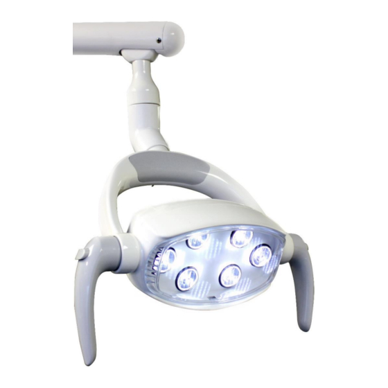
- Page 1 EXCEL LED Dental Examination Light Operating & Installation Manual QAM.EXCEL.0119.4...
- Page 2 Page 1 of 35...
-
Page 3: Table Of Contents
Table of Contents 1. Introduction ................... 3 1.1 Supported Lights ................3 1.2 Installation Notice ................4 1.3 Pre-Installation Responsibilities and component packing list ......5 1.4 Technical Drawings ................6 2. Technical Specifications ................8 3. Operation ....................9 3.1 Pre-Start Checks ................ -
Page 4: Introduction
1. Introduction Thank you for choosing a Daray EXCEL dental light. The Excel lights are specifically designed to meet the demanding needs of today’s dental industry whilst providing the finest quality design with superior performance, reliability and value. The EXCEL is mounted on Daray’s characteristic balanced suspension arm system. -
Page 5: Installation Notice
DARAY offer installation services with our equipment. If you choose to opt out of our installation service, DARAY cannot be held responsible for the installation of the product detailed in your order. -
Page 6: Pre-Installation Responsibilities And Component Packing List
1.3 Pre-Installation Responsibilities and component packing list This document is a guide to the steps that need to be performed to correctly install the EXCEL dental light unit. However, the work required to be performed is the responsibility of the owner or designated contractor/s. -
Page 7: Technical Drawings
1.4 Technical Drawings Page 6 of 35... - Page 8 Page 7 of 35...
-
Page 9: Technical Specifications
2. Technical Specifications Light Source Light Intensity (Lux) @ 0.7m 35,000 Lux ±5% Light Intensity Adjustment Range 5% - 100% Colour Temperature (Kelvin) 6,950K ±5% Colour Rendering Index (CRI) Colour Rendering (R9) Light Field Diameter @ 0.7m: 150mm x 70mm ±20mm Number of LED’s Power Consumption 8-12W ±2%... -
Page 10: Operation
3.2 Motion Sensor Operation The EXCEL has two switch systems that can be used to power the light on or off – a motion sensor and a manual switch. The motion sensor is an infrared relay located underneath the lighthead fascia. -
Page 11: Manual Switch Operation
3.3 Manual Switch Operation The manual switch is located on the underside of the stirrup. Sensor Control switch - Flick once to turn the light ON or OFF - Push and hold the switch, to increase or decrease intensity There is an audible beep from the unit when the light reaches one of its variable intensity peaks (highest and lowest). -
Page 12: Handles
3.4 Handles The Excel light has independent handles that can be attached to the lighthead in multiple locations depending on user preference. Note: The handles are removable for cleaning but are NOT suitable for autoclaving To remove the handle, hold it in one hand and press the lock button on the handle to release the locking mechanism. -
Page 13: Installation Guide Section
4. Installation Guide Section Page 12 of 35... -
Page 14: Ceiling Mounted Version (Excelc)
The procedures below are detailed to a high level however If in doubt please consult a qualified electrician. Minimum Room The ceiling mounted version of the EXCEL has a Requirements recommended install height where the bottom of the wall bracket is approximately 1900mm from the floor. -
Page 15: Attachment Methods And Void Suspension
These instructions are based on the assumption of a fresh fit into a room with no previous lighting structures. With installations onto sites with equipment already in place, we recommend that the previous lights’ mounting plate be removed and the new one fitted as if into a fresh fitting. -
Page 16: Lighting Configuration
Daray’s standard mounting recommendation is to have the ceiling plate fixed directly into the ceiling structure whenever possible. This would also be suitable for open surface, non-voided areas with the use of an optional ceiling mount cover. -
Page 17: Downtube Adjustment And Installation
4.1.5 Downtube adjustment and installation The downtube provided will be either 1m as standard or 2m (optional) maximum with a boot on the bottom. It is Daray’s recommendation that the bottom of the downtube is approximately 1900mm from the floor once installed. - Page 18 Now you should put the rubber retainer ring onto the downtube followed by either the ceiling trim or ceiling mount cover. This is to allow the covers to be fixed into position after you have attached the downtube to the ceiling plate. Suspended Ceiling Ceiling Mount Cover trim...
-
Page 19: Wiring And Transformer Layout
Ideally the cable used to power the light should be of a 1.5mm twin and earth type. Daray recommends that the power supplied uses an earthed switched fused spur, protected with a 3amp fuse. -
Page 20: Arm Installation
4.1.7 Arm installation To ensure the smooth rotation of the arm, it is essential that the primary arm spigot is lightly lubricated before being inserted into the boot of the downtube. Place the white nylon washer over the primary arm spigot. -
Page 21: Fitting The Lighthead
Check the variable intensity by either holding your hand in front of the sensor or by pressing and holding the rocker switch. Your new Daray light is now ready for use. See section 3: Operation To gain full support of our warranty please fill in our warranty web form or contact Daray by phone or email. -
Page 22: Wall Mounted Version (Excelw)
It may be necessary to adjust this height, if there are specific medical procedures the light will be used for. If in doubt consult the end user or DARAY. When installing the bracket take consideration of where you want the lighthead to sit when in its lowest position. -
Page 23: Lighting Configuration
4.2.2 Lighting configuration Dependant on the choice of attachment method custom mounting aspects may be required. Daray’s standard mounting recommendation is to have the wall plate fixed directly onto a clear/open surface, weight supporting wall structure. Ultimately the mounting method used is the responsibility of the project engineer or fitter. -
Page 24: Wiring And Transformer Layout
Next you will need to attach the Power Supply Unit (PSU) to the wall directly under the wall mount bracket. The wall mounted PSU is attached via four fixing points located on the inside of the casing. 4.2.5 Wiring and transformer layout Remove the fascia of the PSU by removing the two screws in the front to gain access to the fixing points on the inside. -
Page 25: Fitting The Lighthead
Check the variable intensity by either holding your hand in front of the sensor or by pressing and holding the rocker switch. Your new Daray light is now ready for use. See section 3: Operation To gain full support of our warranty please fill in our warranty web form or contact Daray by phone or email. -
Page 26: Floor Mounted Version (Exceldfm)
Upstand (6ft) Dual arm system (primary arm and spring-balanced) Wiring Excel head 8nr grub screws Toroidal Transformer Determine that you have all of the parts as per the above packing list. The upstand comes as a standard length of 6ft. - Page 27 The spring-balanced arm within the dual arm system within the factory. However, if the springs have settled during transit, you may need to adjust the tension. (See page 30; Section 6) Fig.1 Fig.2 Fig.3 Fig.5 Fig.4 Page 26 of 35...
-
Page 28: Maintenance
The proposed maintenance is only a suggestion. Depending on the use of the product and the operating environment, this may need to be revised more often. Daray would strongly recommend against “quick fixes” with tape, etc. If you cannot resolve a problem then please contact our helpline on 0800 878 9864 or email support@daray.co.uk... -
Page 29: Product Cleaning & Care Guidelines
Acetone-based cleaners (e.g. nail polish remover, Goo-off™) MEK (Methyl Ethyl Ketone) If you are unsure whether you are using the correct cleaning fluids on your DARAY equipment, please feel free to get in touch with us for advice Page 28 of 35... -
Page 30: Fuses And Their Replacement
5.4 Fuses and their replacement Warning: Ensure you isolate the unit from the mains power before any work related to the electrical supply. For the ceiling mounted light, the fuse is located on the ceiling plate within the terminal block connector. The fuse tray can easily be removed and the fuse replaced. -
Page 31: Adjustment Of Arm Balance To Eliminate Drift
6. Adjustment of Arm Balance to Eliminate Drift The jib arm on your DARAY light will have been balanced during manufacture, however over time you may need to occasionally rebalance the arm, particularly if the arm ‘drifts’ into a lower position when you move the head. -
Page 32: Troubleshooting Guide
This can be resolved following the Spring-balanced instructions in section 6 of this user Vertical drift manual, if these instructions do not resolve the issue, please contact Daray Page 31 of 35... -
Page 33: Safety Precautions
If there is damage to the power cable or if exposed wire is visible DO NOT USE 8. Spare Parts CAUTION: Use only genuine ‘DARAY’ replacement lamps as other types may seriously impair the optical performance of the product. ITEM NO PART NAME... -
Page 34: Warranty Information
DARAY Ltd, please read the following information carefully. The DARAY Ltd returns policy provides guidance on when you can return goods we have supplied, and what you can expect from us once you do. To see our detailed returns policy and procedure visit www.daray.co.uk/returns... -
Page 35: Warranty Details
Failure to use or install the product in accordance with the manufacturer’s instructions. 5. Nothing in this warranty shall have the effect of restricting or excluding the liability of Daray in respect of: a) Death and personal injury caused by the negligence of Daray, or for fraud;... - Page 36 Service Notes Page 35 of 35...
- Page 37 Page 36 of 35...
- Page 38 Page 37 of 35...
- Page 39 Page 38 of 35...
- Page 40 DARAY Ltd. Edison House Robian Way Swadlincote Derbyshire United Kingdom DE11 9DH +44 (0)800 878 9864 +44 (0)333 321 0973 sales@daray.co.uk www.daray.co.uk...
Need help?
Do you have a question about the EXCEL and is the answer not in the manual?
Questions and answers