Table of Contents
Advertisement
Quick Links
Advertisement
Table of Contents

Related Manuals for Omron SmartController EX


Summary of Contents for Omron SmartController EX
- Page 1 SmartController EX User’s Guide I602-E-03...
- Page 2 Copyright Notice The information contained herein is the property of Omron Adept Technologies, Inc., and shall not be reproduced in whole or in part without prior written approval of Omron Adept Technologies, Inc. The information herein is subject to change without notice and should not be construed as a commitment by Omron Adept Technologies, Inc.
-
Page 3: Table Of Contents
Chapter 3: Installation 3.1 Controller Installation Before Unpacking Upon Unpacking Repacking for Relocation Space Around the Chassis Mounting the SmartController EX Motion Controller Mounting Kits Memory Card 3.2 Connecting Power 24 VDC Power Specifications 24 VDC Power Cabling DC Power Connectors... - Page 4 4.6 Connecting User-Supplied Digital I/O Equipment DeviceNet Connector XDIO Connector 4.7 Belt Encoder Interface Chapter 5: Technical Specifications 5.1 SmartController EX Motion Controller Dimensions 5.2 Front Panel Dimensions 5.3 T20 Pendant Dimensions Chapter 6: DeviceNet 6.1 DeviceNet Specifications 6.2 Limitations of the DeviceNet Scanner 6.3 DeviceNet Port on the Controller...
- Page 5 Revision Date Revised Content code June, Original release 2016 October, Added OAT part number for non-Omron sales channels, updated 2016 Omron logo in graphics March, Added WEEE disposal information. Updated all www.adept.com references to www.ia.omron.com. 2019 Updated copyright for 2019. Added information about optional Mounting Kits.
-
Page 7: Chapter 1: Introduction
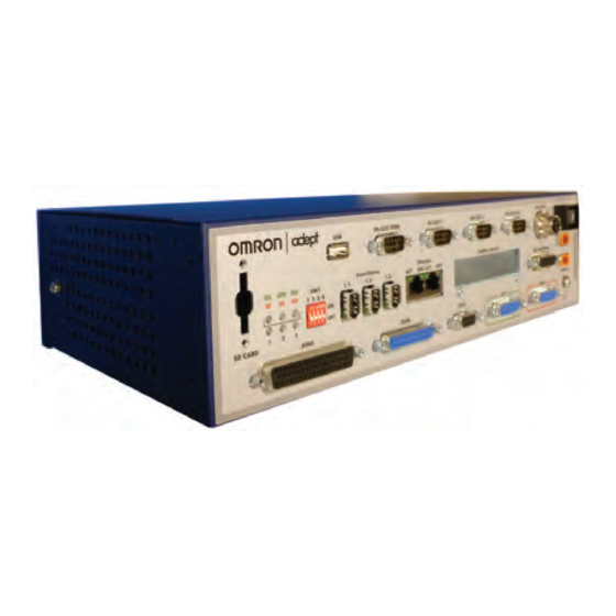
Chapter 1: Introduction 1.1 Product Description The SmartController EX motion controller is a member of the Omron Adept Technologies, Inc. family of high-performance distributed motion controllers. The SmartController is designed for use with Quattro, Hornet, eCobra, and Viper robots. Figure 1-1. SmartController EX Motion Controller... - Page 8 1.1 Product Description Figure 1-2. T20 Pendant SmartController EX User's Guide 11069-000 Rev. H...
-
Page 9: How Can I Get Help
Related Manuals This manual covers the installation and maintenance of a SmartController EX motion con- troller. There are additional manuals that cover programming the system, reconfiguring installed components, and adding other optional components. The following manuals provide information on advanced configurations and system specifications. -
Page 11: Chapter 2: Safety
Table 2-1. Alert Icon Meaning Icon Meaning This is a generic alert icon. Any specifics on the risk will be in the text following the signal word. This identifies a hazardous electrical situation. 11069-000 Rev. H SmartController EX User's Guide... -
Page 12: Special Information
2.4 Additional Safety Information We provide other sources for more safety information: Manufacturer’s Declarations This lists the standards with which the robots and controllers comply. The Manufacturer’s Declarations are in the Manufacturer's Declaration Guide. SmartController EX User's Guide 11069-000 Rev. H... -
Page 13: Robot Safety Guide
The manual control pendant can only move one robot at a time, even if multiple robots are connected to a SmartController EX, and the pendant is connected to the SmartController EX. 2.5 Disposal Dispose of in accordance with applicable regulations. -
Page 15: Chapter 3: Installation
Compare the actual items received (not just the packing slip) with your equipment purchase order, and verify that all items are present and that the shipment is correct. Inspect each item for external damage as it is removed from its container. Contact Omron Adept Technologies, Inc. immediately if any damage is evident. -
Page 16: Repacking For Relocation
3.1 Controller Installation 1. Remove the SmartController EX motion controller from its box. Place it near the robot or mount it in a rack. For details, see Mounting the SmartController EX Motion Controller on page 16. 2. Remove the optional T20 pendant from its box and place it on a flat surface near the SmartController EX motion controller. - Page 17 14.2 482.8 TYP. Figure 3-1. Rack-Mounting the SmartController EX Motion Controller (Units in mm) Panel-Mounting the SmartController EX Motion Controller To panel-mount the controller, install two brackets on each side at the rear of the unit, as shown in the following figure. Use the screws from the accessories kit.
- Page 18 16.0 346.6 359.8 Figure 3-2. Panel-Mounting the SmartController EX Motion Controller (Units in mm) Table-Mounting the SmartController EX Motion Controller To table-mount the controller, install two brackets on each side near the bottom of the unit, as shown in the following figure. These brackets must be ordered separately. They do not come with the controller.
- Page 19 Figure 3-3. Table-Mounting the SmartController EX Motion Controller (Units in mm) Stack-Mounting Components To stack-mount the SmartController EX motion controller and a compatible unit, such as a SmartVision MX vision controller, install two brackets on each side of the units, as shown in the following figure.
-
Page 20: Memory Card
The SmartController EX motion controller is equipped with a Secure Digital (SD) memory card. The SD card is removable, and can be moved to another SmartController EX motion con- troller for testing. The SD card shipped with all systems is factory-configured and installed. The SD card stores the eV+ operating system, application programs, data files, and licenses. - Page 21 CAUTION: Do not remove the SD card when power is connected to the con- troller. Removing an SD Card To remove an SD card from a SmartController EX motion controller: 1. Make sure that the controller is disconnected from its power source. 2. Locate the SD compartment (see the following figure).
-
Page 22: Connecting Power
Once installed, we recommend that you do not repeatedly remove and insert the SD card. 3.2 Connecting Power The SmartController EX motion controller requires filtered 24 VDC power. NOTE: Users must provide their own power supply. Make sure the power cables and power supply conform to the specifications that follow. -
Page 23: Vdc Power Cabling
DIN-Rail Mount NOTE: The power requirements for the user-supplied power supply will vary depending on the configuration of the SmartController EX motion controller and connected devices. A minimum configuration of the controller, front panel, and pendant will require 2 A at 24 VDC. However, a 24 V, 5 A power supply is recommended to allow for additional current draw from connected devices, such as external IEEE 1394 devices and digital I/O loads. -
Page 24: Dc Power Connectors
Chassis Grounding The SmartController EX motion controller is equipped with a grounding point, as shown in the following figure. We recommend connecting a ground wire from the grounding point on SmartController EX User's Guide... -
Page 25: Installing 24 Vdc Connectors
Installing 24 VDC Connectors Use the supplied connector to connect the user-supplied 24 VDC power supply to the SmartController EX motion controller. 1. Locate the 24 VDC connector shipped with the controller. See the following figure. 2. Use 14 or 16 gauge wire to connect the 24 VDC power supply to the controller. -
Page 26: System Cable Installation
IEEE 1394 Cable Specifications We supply the IEEE 1394 cables to connect the SmartController EX motion controller to other devices in the system. If you need a cable of a different length than those supplied, then you must purchase a cable from one of the approved vendors listed below: CEI: www.componentsexpress.com... -
Page 27: Chapter 4: Operation
4.1 Connectors and Indicators Figure 4-1. SmartController EX Connectors and Indicators All of the connectors on the SmartController EX motion controller use standard-density spa- cing, D-subminiature connectors. For customization purposes, the user needs to provide con- nectors of the appropriate gender and pin count, or purchase optional factory-supplied cables. - Page 28 User's Guide, chapter 3, for information on those LEDs with ePLC Connect. The bottom three LEDs on the front of the SmartController EX motion controller give the following information about the status of the main controller. O = Off...
- Page 29 For example, an external E-Stop can be connected to the XUSR connector. A line E-Stop from other equipment can be con- nected. A muted safety gate that causes an E-Stop only in Automatic mode is included. 11069-000 Rev. H SmartController EX User's Guide...
- Page 30 Also included are contacts to report the status of E-Stop push-buttons and the Manual / Automatic switch. NOTE: The SmartController EX motion controller ships with a terminator plug attached to the XUSR connector. The terminator plug must be installed in the absence of any user-supplied safety equipment used to close the E-Stop circuit.
-
Page 31: Front Panel
Before running programs, either the optional Front Panel or user-supplied switches for High Power ON/ OFF, MAN / AUTO, and E-Stop must be connected to the XFP connector on the SmartController EX motion controller. NOTE: Safety regulations dictate the sequence of events required for the user to enable high power. -
Page 32: Installing The Ace Software
3. Verify that your system meets the minimum requirements described in the System Requirements section. 4. After reviewing the information, click the close icon ( ) in the upper-right corner of the ReadMe file window to close it. SmartController EX User's Guide 11069-000 Rev. H... -
Page 33: Configuring The Smartcontroller
8. After the installation has completed, you may be prompted to restart your computer. The ACE software installer adds an "ACE" shortcut to your desktop. You can also launch ACE from the program group added to the Omron > ACE folder on your Windows Programs menu. -
Page 34: Rs-232 Connectors
RS-422 / 485 Connector The RS-422 / 485 connector is a 9-pin DB9 male connector. The pin assignments are shown in the following table. RS-422 is a point-to-point protocol for connecting to a single destination. SmartController EX User's Guide 11069-000 Rev. H... -
Page 35: Connecting User-Supplied Safety And Power-Control Equipment
N/C contacts, Shorted if NOT Used assembly line E-Stop inter- connection. Does not affect E-Stop indication (pins 7, 20)) 4, 17 Line E-Stop (same as pins 3, 16) N/C contacts, Shorted if NOT Used 11069-000 Rev. H SmartController EX User's Guide... - Page 36 9, 22 Manual / Automatic indication CH 1 Contacts are closed in Automatic mode 10, 23 Manual / Automatic indication CH 2 Contacts are closed in Automatic mode 11, 12, No connection 13, 24, SmartController EX User's Guide 11069-000 Rev. H...
- Page 37 Users must exercise caution to avoid inadvertently connecting 24 V signals to these pins, because this will damage the electronics. NOTE: The system was evaluated by Underwriters Laboratory with a factory Front Panel. If you provide a substitute Front Panel, this could void UL com- pliance. 11069-000 Rev. H SmartController EX User's Guide...
- Page 38 Auto Mode ESTOP Ckt. CH 2 No Connection ESTOPSRC 24 V Output to Slave ESTOP NOTE: The XSYS connector is used to link the E-Stop system to our robots. It is not intended for customer connections. SmartController EX User's Guide 11069-000 Rev. H...
- Page 39 Chapter 4: Operation The following figure shows an E-Stop diagram for the SmartController EX motion controller. See Emergency Stop Circuits on page 41 for a description of the functionality of this circuit. SmartController EX 24 V ESTOPSRC XFP-7 XFP-1 XFP-2...
- Page 40 Line E-Stop (external user E-Stop system) User manual / auto indication (manual = open) Muted safety gate - active in auto mode only (jumper closed when not used) Connections at robot or module system (no user connections) SmartController EX User's Guide 11069-000 Rev. H...
-
Page 41: Emergency Stop Circuits
Emergency stop Emergency Stop Circuits The SmartController EX motion controller provides connections for Emergency Stop (E-Stop) circuits on the XUSR and XFP connectors. This gives the controller system the ability to duplic- ate E-Stop functionality from a remote location using voltage-free contacts. See the figure CAT- 3 E-Stop Circuit on XUSR and XFP Connectors on page 39. - Page 42 Automatic mode, but you need to open the gate in Manual mode. If the mute gate is opened in Automatic mode, the robot defaults to Manual mode operation when power is re- SmartController EX User's Guide 11069-000 Rev. H...
-
Page 43: Remote Manual Mode
40 VDC or 30 VAC at a maximum of 1 A. User High Power On Indication In the SmartController EX motion controller, eV+ controls a normally-open relay contact on the XDIO connector (pins 45, 46, see the table XDIO Digital I/O Connector Pin Assignments on page 50), that will close when high power has been enabled. -
Page 44: High Power On / Off Lamp
Customers can build an extension cable to place the Front Panel in a remote location. The extension cable must conform to the following specifications: Wire Size: must be larger than 26 AWG. Connectors: must be 15-pin, standard D-sub male and female. Maximum cable length is 10 meters. SmartController EX User's Guide 11069-000 Rev. H... -
Page 45: Remote Pendant Usage
See DeviceNet on page 59 for details. XDIO Connector The XDIO connector on the SmartController EX motion controller is a 50-pin, standard density D-Sub female connector (see SmartController EX Connectors and Indicators on page 27 for loc- ation). There are 12 inputs and 8 outputs, each optically isolated from the circuitry of the con- troller. - Page 46 The following figure shows inputs 1001 to 1004 with a negative common, inputs 1005 to 1008 with a positive common, and inputs 1009 to 1012 with independent power supply con- nections (no common). NOTE: These are examples. Either method can be used on any channel. SmartController EX User's Guide 11069-000 Rev. H...
- Page 47 NOTE: Power from pins 41-44 and 47-50 can be substituted for the input signal power supply. See the figure Digital Output Wiring Examples for XDIO Con- nector on page 49 and the table Digital I/O Input Circuit Specifications (XDIO connector) on page 46 for additional information. 11069-000 Rev. H SmartController EX User's Guide...
- Page 48 Software scan rate / response time 1 ms scan cycle 1 ms max. response time Turn-off response time (hardware) 200 µsec maximum Software scan rate / response time 1 ms scan cycle 1 ms max. response time SmartController EX User's Guide 11069-000 Rev. H...
- Page 49 XDIO connector. SmartController EX 0001 – 0002 – 0003 – 0004 – 0005 – 0006 – 0007 – 0008 – +24 V (1 A) Figure 4-6. Digital Output Wiring Examples for XDIO Connector 11069-000 Rev. H SmartController EX User's Guide...
- Page 50 HDP-20 series D-Sub Connectors. Crimp snap-in contacts. Order item 1 (includes cover) or item 2 (no cover). Contact pins not included, order separately (item 3, quantity 50). 1. 1658661-1 Kit (Connector body, shield, enclosure, jackscrews) 2. 1658641-2 Connector body only SmartController EX User's Guide 11069-000 Rev. H...
-
Page 51: Belt Encoder Interface
SmartController CX. The 15-pin adapter is P/N: 09443-000. Each 15-pin adapter provides two M12 connections. All encoder inputs for the SmartController EX motion controller use a scheme similar to an RS- 422 differential receiver based on industry standard 75175 integrated circuits. The difference is that a custom resistor network and two differential receivers are used on each of the A and B inputs. - Page 52 ENC3_B- ENC1_A- ENC4_B+ ENC2_A+ ENC4_B- ENC2_A- ENC1_Z+ ENC3_A+ ENC1_Z- ENC3_A- ENC2_Z+ ENC4_A+ ENC2_Z- ENC4_A- ENC3_Z+ ENC1_B+ ENC3_Z- ENC1_B- ENC4_Z+ ENC2_B+ ENC4_Z- Pin 9 Pin 1 Pin 18 Pin 10 Pin 26 Pin 19 SmartController EX User's Guide 11069-000 Rev. H...
- Page 53 (1 A max.) – 2.2K 26LS33 – A – 2.2K B – I – Figure 4-7. Belt Encoder Typical Input Circuit Table 4-16. Belt Encoder Typical Input Descriptions Item Description Encoder 1 Encoder 2 Shield 11069-000 Rev. H SmartController EX User's Guide...
- Page 54 4.7 Belt Encoder Interface Figure 4-8. Belt Encoder Connector SmartController EX User's Guide 11069-000 Rev. H...
-
Page 55: Chapter 5: Technical Specifications
Chapter 5: Technical Specifications This chapter shows the dimensions of the SmartController EX motion controller, Front Panel, and T20 pendant. 5.1 SmartController EX Motion Controller Dimensions NOTE: The dimensions for the legacy CS and CX SmartController motion con- trollers were the same as these. -
Page 56: Front Panel Dimensions
5.2 Front Panel Dimensions 5.2 Front Panel Dimensions 152.4 38.7 55.9 88.9 16.5 13.1 129.5 4x M4 x 18 mm 76.2 139.7 Figure 5-2. Front Panel Dimensions (Units in mm) SmartController EX User's Guide 11069-000 Rev. H... -
Page 57: T20 Pendant Dimensions
Chapter 5: Technical Specifications 5.3 T20 Pendant Dimensions Figure 5-3. T20 Pendant Dimensions (Units in mm) 11069-000 Rev. H SmartController EX User's Guide... -
Page 59: Chapter 6: Devicenet
I/O interfaces. 6.1 DeviceNet Specifications Omron Adept Technologies, Inc. is a member of the Open DeviceNet Vendor Association (ODVA), which is independently run and operated and not directly associated with any one company. The ODVA controls DeviceNet technical specifications with help from Special Interest Groups (SIGs). -
Page 60: Limitations Of The Devicenet Scanner
6.2 Limitations of the DeviceNet Scanner 6.2 Limitations of the DeviceNet Scanner The DeviceNet Scanner that is incorporated into the SmartController EX motion controller hard- ware and the eV+ operating system currently supports only a subset of full DeviceNet func- tionality. -
Page 61: Configuring Devicenet
DeviceNet Network on page 66. Configuring DeviceNet The SmartController EX motion controller has a default configuration such that, if you plug in a DeviceNet module configured with a baud rate of 125 kbps, the first 64 inputs and 64 out-... - Page 62 DeviceNet allows devices to be powered directly from the bus, and devices can use the same cable to communicate with other devices on the bus. DeviceNet nodes are hot-pluggable — you can remove or add components on the bus without powering down the network. SmartController EX User's Guide 11069-000 Rev. H...
- Page 63 100 m 100 m (328 ft) (328 ft) (328 ft) Maximum Drop Length (20 ft) (20 ft) (20 ft) Cumulative Drop Length 156 m 78 m 39 m (512 ft) (256 ft) (128 ft) 11069-000 Rev. H SmartController EX User's Guide...
- Page 64 Red and black DC power pair PVC (15 AWG 19 x 28 tinned and stran- ded copper conductors 18 AWS 19 x 30 tinned copper-stranded drain wire Aluminum / mylar shield over each pair External jacket SmartController EX User's Guide 11069-000 Rev. H...
-
Page 65: Devicenet Connectors
DeviceNet allows different connectors, which may be grouped into open and sealed con- nectors. The open connectors are available with screw or with crimp connectors. The sealed connectors are available in mini-style and micro-style sizes. See the following figure and table for more details. 11069-000 Rev. H SmartController EX User's Guide... -
Page 66: Termination Of The Devicenet Network
Must be sealed if the end node uses a sealed tee. Must be open if the end node uses an open-style tap. The SmartController EX has a terminating resistor built-in, which can be used for one end of the DeviceNet network. -
Page 67: Power Supply And The Devicenet Bus
The DeviceNet network allows distribution of power supplies on the network cable system. Fol- low these general rules to achieve safe and reliable operation: Use power supplies rated at 24 V. Minimize installation problems by using a single power supply with sufficient current 11069-000 Rev. H SmartController EX User's Guide... - Page 68 Provide over-current protection for each segment of your DeviceNet cable installation. The SmartController EX CAN driver (CAN_H / CAN_L) is protected for shorts to the power ter- minals. The driver is protected for voltages in the range from -27 to +40 V.
- Page 69 It is important to note that voltage differences between the V– and V+ conductors need to be between 11 V and 25 V. The common-mode voltage between any two places on the V– wire must not exceed 5 V. Figure 6-7. Micro-Style DeviceNet Connector Pinouts (Viewed from Contact End) 11069-000 Rev. H SmartController EX User's Guide...
- Page 70 6.4 DeviceNet Physical Layer and Media Table 6-9. Micro-Style DeviceNet Connector Pinout Legend Item Description Male Connector (pins) Female Connector (sockets) Drain (bare) V+ (red) V- (black) CAN_H (white) CAN_L (blue) SmartController EX User's Guide 11069-000 Rev. H...
- Page 72 OMRON ASIA PACIFIC PTE. LTD. OMRON ADEPT TECHNOLOGIES, INC. No. 438A Alexandra Road # 05-05/08 (Lobby 2), 4550 Norris Canyon Road, Suite 150, San Ramon, CA 94583 U.S.A. © OMRON Corporation 2019 All Rights Reserved. Alexandra Technopark, Tel: (1) 925-245-3400/Fax: (1) 925-960-0590 Singapore 119967...
Need help?
Do you have a question about the SmartController EX and is the answer not in the manual?
Questions and answers