Table of Contents
Advertisement
Advertisement
Chapters
Table of Contents

Related Manuals for Omron CPM2A - 11-2005


Summary of Contents for Omron CPM2A - 11-2005
- Page 2 CPM2A Programmable Controllers Operation Manual Revised November 2005...
- Page 4 1. Indicates lists of one sort or another, such as procedures, checklists, etc. OMRON, 1999 All rights reserved. No part of this publication may be reproduced, stored in a retrieval system, or transmitted, in any form, or by any means, mechanical, electronic, photocopying, recording, or otherwise, without the prior written permis- sion of OMRON.
-
Page 6: Table Of Contents
............. . 7 CPM2A 24-VDC CPU Unit Conformance to NK Standards . - Page 7 TABLE OF CONTENTS Appendices A Standard Models ............
- Page 8 Section 4 describes how to connect the Programming Console, and how to perform the various program- ming operations. Section 5 describes how to perform a test run and how to diagnose and correct the hardware and soft- ware errors that can occur during PC operation.
- Page 9 Warranty and Limitations of Liability Á Á Á Á Á Á Á Á Á Á Á Á Á Á Á Á Á Á Á Á Á Á Á Á Á Á Á Á Á Á Á Á Á WARRANTY Á...
- Page 10 Application Considerations Á Á Á Á Á Á Á Á Á Á Á Á Á Á Á Á Á Á Á Á Á Á Á Á Á Á Á Á Á Á Á Á Á SUITABILITY FOR USE Á Á Á Á Á Á Á Á Á Á Á Á Á Á Á Á Á Á Á Á Á Á Á Á Á Á Á Á Á Á Á Á Á...
- Page 11 Disclaimers Á Á Á Á Á Á Á Á Á Á Á Á Á Á Á Á Á Á Á Á Á Á Á Á Á Á Á Á Á Á Á Á Á CHANGE IN SPECIFICATIONS Á Á Á Á Á Á Á Á Á Á Á Á Á Á Á Á Á Á Á Á Á Á Á Á Á Á Á Á Á Á Á Á Á...
- Page 13 This section provides general precautions for using the Programmable Controller (PC) and related devices. The information contained in this section is important for the safe and reliable application of the Programmable Con- troller. You must read this section and understand the information contained before attempting to set up or operate a PC system.
-
Page 14: Intended Audience
WARNING It is extremely important that a PC and all PC Units be used for the specified purpose and under the specified conditions, especially in applications that can directly or indirectly affect human life. You must consult with your OMRON representative before applying a PC System to the above-mentioned applications. -
Page 15: Operating Environment Precautions
When connecting the PC to a personal computer or other peripheral device, ei- ther ground the 0-V side of the PC or do not ground the PC at all. Although some grounding methods short the 24-V side, as shown in the following diagram, nev- er do so with the PC. -
Page 16: Application Precautions
100 Ω when installing the Units. Not connecting to the correct ground may result in electric shock. • Always turn OFF the power supply to the PC before attempting any of the fol- lowing. Not turning OFF the power supply may result in malfunction or electric shock. - Page 17 Incorrect tightening torque may result in malfunction. • Be sure to leave the labels attached at the time of shipment on the CPM1 or CPM2A when wiring in order to prevent wiring cuttings from entering the Unit.
-
Page 18: Ec Directives
Conformance to EC Directives The CPM2A PCs comply with EC Directives. To ensure that the machine or de- vice in which the CPM2A PC is used complies with EC directives, the PC must be installed as follows: 1, 2, 3... - Page 19 EMC Directives. However, the noise generated when the PC is switched ON or OFF using the relay output may not satisfy these standards. In such a case, a noise filter must be connected to the load side or other appropriate coun- termeasures must be provided external to the PC.
- Page 20 EC Directives Countermeasure Examples When switching an inductive load, connect a surge protector, diodes, etc., in par- allel with the load or contact as shown below. Circuit Current Characteristic Required element CR method If the load is a relay or solenoid, there The capacitance of the capacitor must be 1 to 0.5 µF per contact current of...
-
Page 21: Cpm2A 24-Vdc Cpu Unit Conformance To Nk Standards
Surge immunity testing conditions when using a 24-VDC CPU Unit of the CPM2A are as follows: • Connect a Transit Voltage Suppressor (TVS) diode between the 24-V and 0-V DC power supply wiring. The polarity of the TVS diode is bidirectional, i.e., it has no set polarity. Recommended TVS: 1.5KE33CA Manufacturer: Vishay Semiconductors (formerly General Semiconductors) ST Microelectronics K.K. -
Page 22: Introduction
SECTION 1 Introduction This section describes the CPM2A’s special features and functions, shows the possible system configurations, and outlines the steps required before operation. Read this section first when using the CPM2A for the first time. Refer to the CPM1/CPM1A/CPM2A/CPM2C/SRM1(-V2) Programming Manual (W353) for details on programming opera- tion. -
Page 23: Cpm2A Features And Functions
Also, the CPM2A CPU Unit is a stand-alone Unit that can han- dle a broad range of machine control applications, so it is ideal for use as a built- in control unit in equipment. - Page 24 Up to 3 Analog I/O Units can be connected to provide analog inputs and outputs. Each Unit provides 2 analog inputs and 1 analog output, so a maximum of 6 ana- log inputs and 3 analog outputs can be achieved by connecting 3 Analog I/O Units.
- Page 25 When used as single-phase pulse outputs, there can be two outputs with a fre- quency range of 10 Hz to 10 kHz with a fixed duty ratio or 0.1 to 999.9 Hz with a variable duty ratio (0 to 100% duty ratio).
- Page 26 The built-in clock (accuracy within 1 minute/month) can be read from the pro- gram to show the current year, month, day, day of the week, and time. The clock can be set from a Programming Device (such as a Programming Console) or the time can be adjusted by rounding up or down to the nearest minute.
- Page 27 High-speed 1:1 NT Link In a 1:1 NT Link, an OMRON Programmable Terminal (PT) can be connected Communications directly to the CPM2A. The PT must be connected to the RS-232C port; it cannot be connected to the Peripheral port. OMRON PT...
-
Page 28: Overview Of Cpm2A Functions
2 controls (setting ranges: 0 to 200 BCD) Input time constant Determines the input time constant for all inputs. (Settings: 1, 2, 3, 5, 10, 20, 40, or 80 ms) Calendar/Clock Shows the current year, month, day of the week, day of the month, hour, minute, and... - Page 29 One analog output: output range 0 to 10 V, –10 to 10 V, or 4 to 20 mA Analog I/O Unit functions (CPM1A-MAD11) (resolution: 1/6000) Two analog inputs: input range 0 to 5 V, 1 to 5 V, 0 to 10 V, –10 to 10 V, 0 to 20 mA, or 4 to 20 mA One analog output: output range 1 to 5 V, 0 to 10 V, –10 to 10 V, 0 to 20 mA, or 4 to...
-
Page 30: Basic System Configurations
CPM2A-60CDT1-D 1-2-2 CPU Unit, Expansion Units, and Expansion I/O Units Up to 3 Expansion Units or Expansion I/O Units can be connected to the expan- sion connector with expansion I/O connecting cables. (Only one Expansion Unit or Expansion I/O Unit can be connected if an NT-AL001 Adapter is connected to the RS-232C port because the CPU Unit’s 5-VDC power supply is limited.) - Page 31 Basic System Configurations Section A PC with 6 analog inputs and 3 analog outputs (the maximum) can be as- sembled by connecting three Analog I/O Units. (Only one Analog I/O Unit can be connected if an NT-AL001 Adapter is connected to the CPU Unit’s RS-232C port.)
- Page 32 Unit, only one additional Expansion Unit (other than a CPM1A-TS002/102) or one Expansion I/O Unit can be connected to the CPU Unit. 2. Only one Expansion Unit can be connected if an NT-AL001 Adapter is con- nected to the CPU Unit’s RS-232C port.
-
Page 33: Structure And Operation
It will be necessary to turn the power off and then on again to enable a new setting if the parameter is ac- cessed only when the power is turned on. -
Page 34: Operating Modes
Console will display a message prompting the user to enter a pass- word. (For details, refer to page 85.) This is because, in order to write data to the PC, the PT automatically switches the operating mode from RUN mode to MON- ITOR mode. -
Page 35: Pc Operation At Startup
Momentary Power Interruption A power interruption will not be detected and CPU Unit operation will continue if the power interruption lasts less than 10 ms for an AC power supply or 2 ms for a DC power supply. A power interruption may or may not be detected for power interruptions some- what longer than 10 ms for an AC power supply or 2 ms for a DC power supply. -
Page 36: Cyclic Operation And Interrupts
1-3-5 Cyclic Operation and Interrupts Basic CPU Operation Initialization processing is performed when the power is turned on. If there are no initialization errors, the overseeing processes, program execution, I/O refresh- ing, and communications port servicing are performed repeatedly (cyclically). - Page 37 The cycle time is the sum of the time required for program execution, I/O refresh- ing, and communications port servicing. A minimum cycle time (1 to 9,999 ms) can be set in the PC Setup (DM 6619). When a minimum cycle time has been set, CPU operation is paused after pro- gram execution until the minimum cycle time is reached.
- Page 38 Normally, the results of interrupt program execution are transferred to I/O memory just after program execution (during I/O refreshing), but IORF(97) can be used to refresh a specified range of I/O words during execution of the inter- rupt program. The specified range of I/O words will be refreshed when IORF(97) is executed.
-
Page 39: Functions Listed By Usage
Functions Listed by Usage Section When IORF(97) is used, the cycle time is extended by the time required to re- fresh the specified I/O words. Overseeing processes Main program IORF(97) executed. Cycle Immediate refreshing time I/O refreshing I/O refreshing RS-232C port servicing... - Page 40 Functions Listed by Usage Section Usage Function Refer Multiply the input pulse frequency from a high-speed counter by a fixed Pulse synchronization and analog W353 multiple, convert that value to an analog value, and output as an output function analog output.
- Page 41 Turn ON the IOM Hold Bit (SR 25212). operation. Retain the contents of I/O memory when the PC is Turn ON the IOM Hold Bit (SR 25212) and set the PC turned on. Setup (DM 6601) so that the status of the IOM Hold Bit is maintained at startup.
-
Page 42: Comparison With The Cpm1A
Comparison with the CPM1A Item CPM2A CPM1A Instruction set Basic instructions Same as CPM2A. Special instructions 105 instructions, 185 variations 79 instructions, 139 variations LD: 0.64 µs LD: 1.72 µs Instruction Basic instructions execution times MOV(21): 7.8 µs MOV(21): 16.3 µs... - Page 43 Reading range-comparison Check AR 1100 to AR 1107 or Check AR 1100 to AR 1107. results execute PRV(62). Reading status Check AR 1108 (comparison in...
- Page 44 1:1 PC LInk 1:1 NT Link Input time constant Can be set to 1, 2, 3, 5, 10, 20, Can be set to 1, 2, 4, 8, 16, 32, 40, or 80 ms. (Default: 10 ms) 64, or 128 ms. (Default: 8 ms)
- Page 45 Supports the pulse output PV read operation. CTBL(63) COMPARISON TABLE The count is compared with all of the target values The count is compared LOAD in the target value comparison table. with each target value in the order that they appear in the target value comparison table.
- Page 46 Before using a CPM1A program containing one or more of the instructions in the table above, check the program to be sure that it will operate properly and edit the program if necessary. The CPM2A may not operate properly if a CPM1A pro- gram with these instructions is transferred and executed unchanged.
-
Page 47: Preparation For Operation
Error Log Area DM 2000 to DM 2021 DM 1000 to DM 1021 Note CPM1A programs that use the Error Log Area cannot be used in the CPM2A without editing the program to change the location of the Error Log Area. - Page 48 Refer to the Programming Manual for details. 6. Write Ladder Program in PC • Write the ladder program in the PC with the Programming Console or transfer the program to the PC from the Support Software. Refer to Section 4 Using Programming Devices, to the SYSMAC Support Software Operation Manuals and to the CPT User Manual for details.
-
Page 49: Unit Specifications And Components
SECTION 2 Unit Specifications and Components This section provides the technical specifications of the Units that go together to create a CPM2A PC and describes the main components of the Units. Specifications ............ -
Page 50: Specifications
Terminal screw size Power interrupt time AC power supply: 10 ms min. DC power supply: 2 ms min. (A power interruption occurs if power falls below 85% of the rated voltage for longer than the power interrupt time.) CPU Unit AC power 650 g max. -
Page 51: Characteristics
I/O Units Input bits IR 00000 to IR 00915 (Words not used for input bits can be used for work bits.) Output bits IR 01000 to IR 01915 (Words not used for output bits can be used for work bits.) - Page 52 Input time constant Can be set for all input points. (ON response time = (1 ms, 2 ms, 3 ms, 5 ms, 10 ms, 20 ms, 40 ms, or 80 ms) OFF response time) Clock function Shows the year, month, day of the week, day, hour, minute, and second.
-
Page 53: I/O Specifications
Internal 750 Ω circuits Note The input time constant can be set to 1, 2, 3, 5, 10, 20, 40, or 80 ms in the PC Setup. High-speed Counter Inputs Inputs IN00000 through IN00002 can be used as high-speed counter inputs, as shown in the following table. - Page 54 Internal 750 Ω circuits Note The input time constant can be set to 1, 2, 3, 5, 10, 20, 40, or 80 ms in the PC Setup. Caution Do not apply voltage in excess of the rated voltage to the input terminal. It may...
- Page 55 250 VAC: 2 A 24 VDC: 2 A Note The service life of relay output contacts shown in the table assumes the worst conditions. The following graph shows the results of OMRON’s service life tests at a switching rate of 1,800 times/hour.
- Page 56 0.1 A, the transistor will generate more heat and com- ponents may be damaged. 2. The total for OUT01000 to OUT 01003 must be 0.8 A maximum. If the ambi- ent temperature is maintained below 50 °C, however, up to 0.9 A/common can be used.
-
Page 57: Unit Components
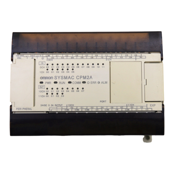
Unit Components Section 2-2 Unit Components 2-2-1 CPU Unit Components CPU Units with 20 or 30 I/O Terminals 3. Protective ground terminal 2. Functional ground terminal (AC power supplies only) 5. Input terminals 1. Power supply input terminals 8. Input indicators 10. - Page 58 1, 2, 3... 1. Power Supply Input Terminals Connect the power supply (100 to 240 VAC or 24 VDC) to these terminals. 2. Functional Ground Terminal ( Be sure to ground this terminal (AC-type PCs only) to enhance immunity to noise and reduce the risk of electric shock.
- Page 59 Unit Components Section 2-2 10. Analog Controls Turn these controls to change the analog settings (0 to 200) in IR 250 and IR 251. 11. Peripheral Port Connects the PC to a Programming Device (including Programming Consoles), host computer, or standard external device.
-
Page 60: Expansion I/O Unit Components
2. Output Terminals Connects the CPU Unit to external output devices. 3. Input Indicators The input indicators are lit when the corresponding input terminal is ON. 4. Output Indicators The output indicators are lit when the corresponding output terminal is ON. -
Page 61: Analog I/O Unit Components
Unit Components Section 2-2 Caution Do not touch the expansion I/O connecting cable while the power is being sup- plied in order to prevent any malfunction due to static electricity. 6. Expansion Connector Connects to another Expansion I/O Unit or an Expansion Unit (Analog I/O Unit, Temperature Sensor Unit, or CompoBus/S I/O Link Unit). -
Page 62: Temperature Sensor Unit Components
Unit Components Section 2-2 Caution Do not touch the Expansion I/O Unit Connecting Cable while the power is being supplied in order to prevent any malfunction due to static electricity. 3. Expansion Connector Connects to another Expansion Unit (Expansion I/O Unit, Analog I/O Unit, or CompoBus/S I/O Link Unit). -
Page 63: Compobus/S I/O Link Unit Components
Temperature Sensor Unit and cannot be removed. Caution Do not touch the expansion I/O connecting cable while the power is being sup- plied in order to prevent any malfunction due to static electricity. 5. Expansion Connector Connects to an additional Expansion I/O Unit or another Expansion Unit. -
Page 64: Devicenet I/O Link Unit Components
PC’s CPU Unit, an Expansion I/O Unit, or another Expansion Unit. Caution Do not touch the expansion I/O connecting cable while the power is being sup- plied in order to prevent any malfunction due to static electricity. 5. Expansion Connector Connects to an Expansion I/O Unit or another Expansion Unit (Analog I/O Unit, Temperature Sensor Unit, or CompoBus/S I/O Link Unit). - Page 65 PC’s CPU Unit or another Expansion Unit. This cable cannot be removed. Caution Do not touch the Expansion I/O Unit Connecting Cable while the power is being supplied in order to prevent any malfunction due to static electricity. 6. Expansion Connector...
-
Page 66: Installation And Wiring
Installation and Wiring This section provides information on installing and wiring a CPM2A PC. Be sure to follow the directions and precautions in this section when installing the CPM2A in a panel or cabinet, wiring the power supply, or wiring I/O. -
Page 67: Design Precautions
Motor forward 01006 Motor reverse In the interlock circuit above, MC1 and MC2 can’t be ON at the same time even if CPM2A outputs 01005 and 01006 are both ON (an incorrect PC operation). Selecting an Installation Site The CPM2A is resistant to harsh conditions and highly reliable, but installing the... -
Page 68: Installation Site Conditions
Selecting an Installation Site Section 3-2 Caution Be sure to install the CPM2A correctly, as outlined in this manual. Failure to do so may result in Unit malfunction. 3-2-1 Installation Site Conditions Note Do not install the CPM2A under any of the following conditions. -
Page 69: Installing The Cpm2A
• The PC will be easiest to access if the panel or cabinet is installed about 3 to 5 feet above the floor. - Page 70 PFP-50N (50 cm) PFP-100N2 (1 m) End Plates (PFP-M) Installation Lower the CPM2A so that the notch on the back of the PC catches the top of the DIN Track. Push the PC forward until the lock snaps into place.
-
Page 71: Connecting An Expansion Unit Or Expansion I/O Unit
Screwdriver 3-3-3 Connecting an Expansion Unit or Expansion I/O Unit Up to 3 Expansion Units or Expansion I/O Units can be connected to a CPM2A CPU Unit. Use the following procedure when connecting an Expansion Unit or Expansion I/O Unit. -
Page 72: Wiring And Connections
3-4-1 General Precautions for Wiring Caution Leave the protective label in place while wiring. The Unit may malfunction if strands of wire get inside the Unit. After completing wiring be sure to remove the label to avoid overheating. Protective label I/O Line Noise Do not run CPM2A I/O lines in the same duct or conduit as power lines. -
Page 73: Removing The Terminal Block
Wiring and Connections Section 3-4 Floor Ducts Leave at least 200 mm between the wiring and the top of the duct, as shown in the following diagram. Control cables and CPM2A I/O lines CPM2A power lines Power cables Metal plate (iron) 200 mm min. -
Page 74: Ground Wiring
2. Lift the terminal block off the CPU Unit. 3-4-3 Ground Wiring Be sure to ground the earth terminal to less than 100 Ω in order to protect against Grounding electric shock and incorrect operation from electrical noise. Be sure to use a wire of at least 1.25 mm... -
Page 75: Power Supply Wiring
Stray wire strands can short-circuit and cause a fire. Use M3 crimp terminals and tighten the terminal screws to a torque of 0.5 N S m. Connect a ring terminal to each terminal screw. Ring terminal... - Page 76 (instead of a stranded wire). Do not connect bare stranded wires directly to ter- minals. Stray wire strands can short-circuit and cause a fire. Use M3 crimp terminals and tighten the terminal screws to a torque of 0.5 N S m. Fork terminal Ring terminal 6.2 mm max.
-
Page 77: Input Wiring
Section 3-4 3-4-5 Input Wiring Wire the inputs to the CPM2A’s CPU Unit and Expansion I/O Units as shown in the following diagrams. Use crimp terminals or solid wires (not stranded wire) to connect to the PC. The power supply output terminals can be used with CPU Units with AC power supplies. - Page 78 Wiring and Connections Section 3-4 CPM2A-40CDR-j, CPM2A-40CDT-D, and CPM2A-40CDT1-D Terminals 00 through 11 of “0CH” correspond to bits IR 00000 through IR 00011, terminals 00 through 11 of “1CH” correspond to bits IR 00100 through IR 00111. Input 24 VDC...
- Page 79 Section 3-4 CPM2A-60CDR-j, CPM2A-60CDT-D, and CPM2A-60CDT1-D Terminals 00 through 11 of “0CH” correspond to bits IR 00000 through IR 00011, terminals 00 through 11 of “1CH” correspond to bits IR 00100 through IR 00111, terminals 00 through 11 of “2CH” correspond to bits IR 00200 through IR 00211.
- Page 80 Wiring and Connections Section 3-4 CPM1A-20EDR1, CPM1A-20EDT, and CPM1A-20EDT1 Terminals 00 through 11 of “mCH” correspond to bits 00 through 11 of word IR m. Input 24 VDC devices CPM1A-8ED Terminals 00 through 07 of “mCH” correspond to bits 00 through 07 of word IR m.
- Page 81 Wiring and Connections Section 3-4 Input Wiring Example A CPU Unit with an AC power supply is shown. CPU Units with DC power sup- plies don’t have power supply outputs. Input devices External power supply output: 300 mA at 24 VDC for CPU Units with 20, 30, 40, or 60 I/O points (CPU Units with a AC power supply input only.)
- Page 82 Wiring and Connections Section 3-4 Input Devices The following table shows how to connect various input devices. Device Circuit diagram Relay output CPM2A 5 mA/12 mA COM (+) NPN open collector Sensor power supply Output CPM2A 5 mA/12 mA COM (+)
- Page 83 24 VDC PC Setup Settings The input bits shown in the following tables can operate as normal inputs or they can be assigned special functions in the PC Setup. Special functions for input bits IR 00000 through IR 00002 are set in DM 6642:...
- Page 84 (IN00000 through IN00002 have different values.) Sensor Surge Current If a sensor power supply is turned ON when the PC is ON and ready to receive inputs, surge current from the sensor may result in an incorrect input. To prevent...
-
Page 85: Output Wiring
00001 01000 Note The SV of TIM 000 can be set to #0001 (0.1 s) to achieve a delay time of 100 ms, but the timer accuracy is 0 to 0.1 s, meaning that the timer’s Completion Flag may turn ON immediately after the timer input. The SV must thus be set to #0002 (0.2 s) or higher to allow for timer accuracy. - Page 86 CPM2A PCs. WARNING The PC outputs may remain ON or OFF due to deposition or burning of the output relays or destruction of the output transistors. External safety measures must be provided to ensure safety in the system. Not providing proper safety measures may result in serious accidents.
- Page 87 Wiring and Connections Section 3-4 CPM2A-40CDR-j Terminals 00 through 07 of “10CH” correspond to IR 01000 through IR 01007. Terminals 00 through 07 of “11CH” correspond to IR 01100 through IR 01107. 250 VAC/ 250 VAC/ 250 VAC/ 250 VAC/...
- Page 88 Section 3-4 CPM2A-60CDR-j Terminals 00 through 07 of “10CH” correspond to IR 01000 through IR 01007. Terminals 00 through 07 of “11CH” correspond to IR 01100 through IR 01107. Terminals 00 through 07 of “12CH” correspond to IR 01200 through IR 01207.
- Page 89 Wiring and Connections Section 3-4 CPM1A-20EDR1 Terminals 00 through 07 of “1nCH” correspond to bits 00 through 07 of word IR 1n. 250 VAC/ 250 VAC/ 250 VAC/ 250 VAC/ 24 VDC 24 VDC 24 VDC 24 VDC CPM1A-8ER Terminals 00 through 07 of “1nCH” correspond to bits 00 through 07 of word IR 1n.
- Page 90 Wiring and Connections Section 3-4 Transistor Output Wiring (Sinking) Wire the outputs to the CPM2A’s CPU Unit and Expansion I/O Units as shown in the following diagrams. • Always use single wire or attach crimp terminals if a stranded wire is used.
- Page 91 Wiring and Connections Section 3-4 CPM2A-40CDT-D Terminals 00 through 07 of “10CH” correspond to IR 01000 through IR 01007. Terminals 00 through 07 of “11CH” correspond to IR 01100 through IR 01107. 4.5 to 4.5 to 4.5 to 4.5 to 30 VDC 4.5 to 30 VDC...
- Page 92 Section 3-4 CPM2A-60CDT-D Terminals 00 through 07 of “10CH” correspond to IR 01000 through IR 01007. Terminals 00 through 07 of “11CH” correspond to IR 01100 through IR 01107. Terminals 00 through 07 of “12CH” correspond to IR 01200 through IR 01207.
- Page 93 Wiring and Connections Section 3-4 CPM1A-20EDT Terminals 00 through 07 of “1nCH” correspond to bits 00 through 07 of word IR 1n. 24 VDC +10%/–15% CPM1A-8ET Terminals 00 through 07 of “1nCH” correspond to bits 00 through 07 of word IR 1n.
- Page 94 Wiring and Connections Section 3-4 Transistor Output Wiring (Sourcing) Wire the outputs to the CPM2A’s CPU Unit and Expansion I/O Units as shown in the following diagrams. • Always use single wire or attach crimp terminals if a stranded wire is used.
- Page 95 Wiring and Connections Section 3-4 CPM2A-40CDT1-D Terminals 00 through 07 of “10CH” correspond to IR 01000 through IR 01007. Terminals 00 through 07 of “11CH” correspond to IR 01100 through IR 01107. 4.5 to 4.5 to 4.5 to 4.5 to 30 VDC 4.5 to 30 VDC...
- Page 96 Section 3-4 CPM2A-60CDT1-D Terminals 00 through 07 of “10CH” correspond to IR 01000 through IR 01007. Terminals 00 through 07 of “11CH” correspond to IR 01100 through IR 01107. Terminals 00 through 07 of “12CH” correspond to IR 01200 through IR 01207.
- Page 97 Wiring and Connections Section 3-4 CPM1A-20EDT1 Terminals 00 through 07 of “1nCH” correspond to bits 00 through 07 of word IR 1n. 24 VDC +10%/–15% CPM1A-8ET1 Terminals 00 through 07 of “1nCH” correspond to bits 00 through 07 of word IR 1n.
- Page 98 Observe the following precautions to protect the PC’s internal components. Output Short Protection The output or internal circuitry might be damaged when the load connected to an output is short-circuited, so it is recommended to install a protective fuse in each...
- Page 99 Do not connect bare stranded wires directly to terminals. Stray wire strands can short-circuit and cause a fire. Use M3 crimp terminals and tighten the terminal screws to a torque of 0.5 N S m. Fork terminal Ring terminal 6.2 mm max.
-
Page 100: Programming Device Connections
Wiring and Connections Section 3-4 3-4-7 Programming Device Connections The CPM2A CPU Unit can be connected to a Programming Console or a host computer running CX-Programmer, SYSMAC Support Software (SSS), or SYS- MAC-CPT Support Software. Programming Console The CPM2A CPU Unit can be connected to a C200H-PRO27-E Programming Console with a standard C200H-CN222 (2 m) or C200H-CN422 (4 m) Connect- ing Cable. -
Page 101: Host Link Connections
Wiring and Connections Section 3-4 Peripheral Port Connection A personal computer can be connected to the CPU Unit’s Peripheral port with a CQM1-CIF01 or CPM1-CIF01 RS-232C Adapter. Using a CQM1-CIF02 Using a CPM1-CIF01 CPM2A CPM2A CPM1-CIF01 CQM1-CIF02 IBM PC/AT or... - Page 102 . Set the switch to OFF to use the settings in the PC Setup. Note The standard settings are: Host Link, 9,600 bps, 7-bit data, 1 start bit, 2 stop bits, and even parity. Refer to Section 1 PC Setup in the Programming Manual...
- Page 103 Wiring and Connections Section 3-4 One-to-N Host Link Up to 32 OMRON PCs, including CPM2A PCs, can be controlled from a host Connection computer. The following diagrams show separate RS-232C port and Peripheral port configurations, but both ports can be used simultaneously.
-
Page 104: No-Protocol Communications
RS-232C port. Refer to Section 1 PC Setup in the Programming Manual (W353) for details on settings. 2. When in RUN mode, if a PT is connected to the RS-232C port via Host Link, the PT will change the PC’s operating mode from RUN mode to MONITOR mode. -
Page 105: One-To-One Pc Link Connections
Setup and set the RS-232C port communications mode to 1:1 PC Link Master in one PC and 1:1 PC Link Slave in the other PC. Refer to Section 1 PC Setup in the Programming Manual (W353) for details on settings. -
Page 106: Compobus/S I/O Link Connections
Section 3-4 3-4-12 CompoBus/S I/O Link Connections A CompoBus/S I/O Link can be used to create an I/O link (remote I/O) of 8 input points and 8 output points with a CompoBus/S Master Unit or SRM1 PC. The connection is made through a CompoBus/S I/O Link Unit. -
Page 107: Using A Programming Console
SECTION 4 Using a Programming Console This section provides information on connecting and using a Programming Console. Refer to 5-3 Programming Console Operation Errors for details on errors that might occur during Programming Console operations. Compatible Programming Consoles ......... . -
Page 108: Compatible Programming Consoles
CQM1-PRO01-E and the C200H-PRO27-E. The key functions for these Pro- gramming Consoles are identical. Press and hold the Shift Key to input a letter shown in the upper-left corner of the key or the upper function of a key that has two functions. For example, the CQM1-PRO01-E’s AR/HR Key can specify either the AR or HR Area;... - Page 109 RUN or MONITOR but it cannot be removed when the switch is set to PROGRAM. Contrast Control The display contrast can be adjusted with the control on the right side of the Pro- gramming Console. Contrast control Buzzer Volume The C200H-PRO27-E’s buzzer volume can be adjusted with the lever on the...
-
Page 110: Changing The Cpm2A's Mode With The Mode Switch
Programming Console screen. Press CLR to clear the display so that key operations can be performed. • If the SHIFT Key is pressed while the mode switch is turned, the original dis- play will remain on the Programming Console’s screen and the mode display won’t appear. -
Page 111: Connecting The Programming Console
Note The default setting is 0000. If a Programming Console is not connected, the PC will automatically enter RUN mode. Be sure that it is safe for the PC to operate before turning on the PC without a Programming Console connected. -
Page 112: Preparation For Operation
The password prevents unauthorized access to the program. The PC prompts you for a password when PC power is turned on or, if PC power is already on, after the Programming Console has been connected to the PC. To gain access to the system when the “Password!”... - Page 113 If the Programming Console is connected to the PC when PC power is already on, the first display below will indicate the mode the PC was in before the Pro- gramming Console was connected. Ensure that the PC is in PROGRAM mode before you enter the password.
-
Page 114: Programming Console Operations
Function Page Clearing memory Clears all or part of the Program Memory and any data areas that are not read-only, as well as the contents of the Programming Console’s memory. Clearing memory completely Clears all of memory, including the user program, PC Setup, all data areas, and the I/O comment area (set with version 2.0 or later of... -
Page 115: Clearing Memory
MONTR Key is pressed. The HR Key is used to specify both the AR and HR Areas, the CNT Key is used to specify the entire timer/counter area, and the DM Key is used to specify the DM Area. -
Page 116: Clearing Memory Completely
5. Press the MONTR Key to clear the specified regions of memory. MONTR 4-2-3 Clearing Memory Completely This operation is used to clear all of memory, including the user program, PC Setup, all data areas, and the I/O comment area (set with version 2.0 or later of CX-Programmer). MONITOR PROGRAM The I/O comment function was supported for the CPM2A starting from version 2.0 of CX-Programmer. -
Page 117: Buzzer Operation
Before inputting a new program, any error messages recorded in memory should be cleared. It is assumed here that the causes of any of the errors for which error messages appear have already been taken care of. If the buzzer sounds when an attempt is made to clear an error message, eliminate the cause of the error, and then clear the error message. -
Page 118: Assigning Expansion Instruction Function Codes
The PC Setup must be set for user-defined expansion instruction assign- ments. Set bits 8 to 11 of DM 6602 to 1 and turn the PC’s power off and then on again to enable the new setting. 1, 2, 3... -
Page 119: Entering Or Editing Programs
I/O monitor display. Press the CLR Key to return to I/O bit status monitoring of the initial address. Note The ON/OFF status of any displayed bit will be shown if the PC is in RUN or MONITOR mode. - Page 120 To specify the Completion Flag for a timer or counter, press the LD, AND, OR, or NOT Key followed by the TIM or CNT Key, and then input the timer/ counter number last. 6. Input the second instruction and operand. (In this case it isn’t necessary to enter the timer number, because it’s 000.) Press the WRITE Key to write the...
- Page 121 SHIFT Input the value of the operand from 0 to 65535. Note If an erroneous input is made, press the CLR Key to restore the status prior to the input. Then enter the correct input. 14. Restore the hexadecimal display.
-
Page 122: Instruction Search
MONITOR PROGRAM The ON/OFF status of any displayed bit will be shown if the PC is in RUN or MONITOR mode. 1, 2, 3... 1. Press the CLR Key to bring up the initial display. -
Page 123: Bit Operand Search
MONITOR PROGRAM The ON/OFF status of any displayed bit will be shown if the PC is in RUN or MONITOR mode. 1, 2, 3... 1. Press the CLR Key to bring up the initial display. - Page 124 1, 2, 3... 1. Press the CLR Key to bring up the initial display. 2. Input the address where the NO condition will be inserted and press the Down Arrow Key. It is not necessary to input leading zeroes. ↓...
-
Page 125: Checking The Program
SRCH 3. Input the desired check level (0, 1, or 2). The program check will begin when the check level is input, and the first error found will be displayed. Note Refer to 5-4 Programming Errors for details on check levels and the errors that may be detected when the program is checked. - Page 126 Programming Console Operations Section Program Read then Monitor When a program address is being displayed, the status of the bit or word in that address can be monitored by pressing the MONTR Key. 1, 2, 3... 1. Press the CLR Key to bring up the initial display.
-
Page 127: Differentiation Monitor
5. Press the SHIFT and CLR Keys to end monitoring altogether. SHIFT Note Press the SHIFT Key, CLR Key, and then CLR Key again to return to the initial Programming Console display with the multiple address monitoring state unchanged. Press the SHIFT Key and then the MONTR Key from the initial dis- play to return to the multiple address monitoring state. -
Page 128: Binary Monitor
2. Press the SHIFT and then the MONTR Key to begin binary monitoring. The ON/OFF status of the selected word’s 16 bits will be shown along the bottom of the display. A 1 indicates a bit is on, and a 0 indicates it is off. SHIFT MONTR... -
Page 129: Three-Word Monitor
In this case, DM 0000 was selected. The Up and Down Arrow Keys can be used to shift one address up or down. The status of the displayed words can be changed at this point. Refer to 4-2-20 Three-word Data Modification. -
Page 130: Unsigned Decimal Monitor
4-2-20 Three-Word Data Modification This operation is used to change the contents of one or more of the 3 con- secutive words displayed in the Three-Word Monitor operation. It is possible in MONITOR or PROGRAM mode only. -
Page 131: Changing Timer, Counter Sv
SV. Inputting a New SV This operation can be used to input a new SV constant, as well as to change an Constant SV from a constant to a word address designation and vice versa. The following examples show how to input a new SV constant and how to change the SV from a constant to an address. -
Page 132: Hexadecimal, Bcd Data Modification
3. Press the Down Arrow, CHG, and then the EXT Key. ↓ The constant on the left is the old SV and the constant on the right will be- come the new SV constant in step 5. 4. Press the Up and Down Arrow Keys to increment and decrement the con- stant on the right. -
Page 133: Binary Data Modification
↓ ↓ b) Use the 1 and 0 Keys to change a bit’s status to on or off. The cursor will move one bit to the right after one of these keys is pressed. c) Use the SHIFT+SET and SHIFT+RESET Keys to force-set or force-re- set a bit’s status. -
Page 134: Unsigned Decimal Data Modification
WRITE Key is pressed. The PV can be set within a range of –32,768 and 32,767. Use the SET Key to input a positive number, and use the RESET Key to input a negative number. -
Page 135: Force Set, Reset
(Multiple address monitor) 2. Press the SET Key to force the bit ON or press the RESET Key to force the bit OFF. The cursor in the lower left corner of the display indicates that the force set/ reset is in progress. -
Page 136: Clear Force Set/Reset
Note If you mistakenly press the wrong key, press CLR and start again from the beginning. 3. Press the NOT Key to clear the force-set/reset status of bits in all data areas. 4-2-28 Hex-ASCII Display Change This operation is used to convert word data displays back and forth between 4-digit hexadecimal data and ASCII. -
Page 137: Displaying The Cycle Time
These differences are caused by changing execution conditions. 4-2-30 Reading and Setting the Clock This operation is used to read or set the CPU’s clock. The clock can be read in any mode, but can be set in MONITOR or PROGRAM mode only. Operation... -
Page 138: Programming Example
Programming Example Section Programming Example This section demonstrates all of the steps needed to write a program with the Programming Console. 4-3-1 Preparatory Operations Use the following procedure when writing a program to the CPM2A for the first time. 1, 2, 3... -
Page 139: Example Program
Section 4-3-2 Example Program The following ladder program will be used to demonstrate how to write a pro- gram with the Programming Console. This program makes output IR 01000 flicker ON/OFF (one second ON, one second OFF) ten times after input IR 00000 is turned ON. -
Page 140: Programming Procedures
4-3-2 Example Program. The procedure is performed beginning with the initial display. (Clear the memory before entering a new program.) Note If an error occurs while inputting the program, refer to 5-3 Programming Console Operation Errors for details on correcting the error. Refer to the relevant Support Software Operation Manual for details on errors that appear when operating the CX-Programmer, SSS, or SYSMAC-CPT Support Software. - Page 141 WRITE 4. Input the SV for T001 (#0010 = 1.0 s). WRITE (3) Inputting the The following key operations are used to input the 2-second timer. Two-second Timer 1, 2, 3... 1. Input the normally open condition IR 20000. WRITE 2.
- Page 142 3. Input the OUT instruction IR 01000. (It isn’t necessary to input leading zeroes.) WRITE (6) Inputting the END(001) Input END(01). (The display shows three digits in the function code, but only the Instruction last two digits are input for CPM2A PCs.) WRITE...
-
Page 143: Checking The Program
SRCH 3. Input the desired check level (0, 1, or 2). The program check will begin when the check level is input, and the first error found will be displayed. If no errors are found, the following display will appear. -
Page 144: Test Runs And Error Processing
SECTION 5 Test Runs and Error Processing This section describes procedures for test runs of CPM2A operation, self-diagnosis functions, and error processing to identify and correct the hardware and software errors that can occur during PC operation. Initial System Checks and Test Run Procedure . -
Page 145: Initial System Checks And Test Run Procedure
2. When contents of the program, read-only DM (DM 6144 through DM 6599), or PC Setup (DM 6600 through DM 6655) have been changed, startup proc- essing will take up to 1,200 ms longer than usual. Be sure to take this one- time startup delay into account if it may affect operations. -
Page 146: Self-Diagnostic Functions
5-2-1 Identifying Errors An error can be identified by the error message displayed on a Programming Device, error flags in the AR and SR areas, and the error code output to SR 253. Fatal and Non-fatal PC errors are divided into 2 categories based on the severity of the errors. The... -
Page 147: User-Defined Errors
FAL number and an FALS number. To clear an FAL error, correct the cause of the error and then execute FAL 00 or use a Programming Device to clear the error. -
Page 148: Fatal Errors
Unit configuration. SYS FAIL FALS** 01 to 99 A FALS(07) instruction has been executed in the program. Check the FALS number to (** is 01 to 99 or 9F.) determine the conditions that caused execution, correct the cause, and clear the error. -
Page 149: Programming Console Operation Errors
Check level 0 checks for type A, B, and C errors; check level 1, for type A and B errors; and check level 2, for type A errors only. -
Page 150: Troubleshooting Flowcharts
OFF) by more than one instruction (e.g., OUT, OUT NOT, DIFU(13), DIFD(14), KEEP(11), SFT(10)). This error occurs when the same number is used for the timer and counter instructions. Although this is allowed for certain instructions, check instruction requirements to confirm that the program is correct or rewrite the program so that each bit is controlled by only one instruction. - Page 151 Tighten screws or Are there any loose terminal screws or bro- replace wires. ken wires? Is PWR indicator lit? Correct the short circuit or limit Has the external the connected load to the spec- power supply shorted ification range. or overloaded?
- Page 152 Section Fatal Error Check RUN indicator not lit. Is the ERR/ALM indicator lit? Determine the cause Is PC mode displayed of the error with a on Programming Device? Programming Device. Is PC mode displayed on Turn the power Programming Device? supply OFF, and then ON again.
- Page 153 Troubleshooting Flowcharts Section Non-fatal Error Check ERR/ALM indicator flashing. Determine the cause of the error with a Programming Device. Identify the error, eliminate its Is a non-fatal error cause, and clear the error. indicated? Flashing Is the ERR/ALM indicator flashing?
- Page 154 Troubleshooting Flowcharts Section I/O Check The I/O check flowchart is based on the following ladder diagram section. (LS1) (LS2) 00002 00003 01003 SOL1 01003 SOL1 malfunction. Malfunction of SOL1 Is the IR 01003 output indicator operating normally? Check the voltage at the Wire correctly.
- Page 155 Operation OK? Operation OK? Are the terminal screws loose? Is input wiring correct? Check operation by using a dummy input signal to turn the input ON and OFF. Wire correctly. Tighten the terminal screws Operation OK? Replace the CPU Unit, Replace the CPU Unit, Return to “start.”...
- Page 156 55°C? Is the ambient Consider using a temperature above heater. 0°C? Is the ambient humidity Consider using an between 10% and air conditioner. 85%? Install surge protec- tors or other noise- Is noise being reducing equipment controlled? at noise sources.
- Page 157 AR 1308 ON? errors, and clear the error. Check the error indicated by AR 1310 to Turned ON during the flag that is ON, correct set- AR 1312 ON? startup? tings as required, and write data to the flash memory.
-
Page 158: Maintenance Inspections
Measurement Devices (May be Needed) • Synchroscope • Cathode-ray oscilloscope • Thermometer, hygrometer Note Do not attempt to disassemble, repair, or modify the PC in any way. * Data will continue to be backed up for one week after a battery error occurs. -
Page 159: Battery Replacement
Section Battery Replacement If power has not been supplied to the PC for an extended period of time, turn ON the power supply for at least 5 minutes before replacing the battery. Turn OFF the power supply to the PC before replacing the battery. - Page 160 4. Check the replacement battery’s connector. 5. Check the alignment of the connector tab and fully insert the connector. 6. Insert the battery into the compartment, making sure that the cord on the battery is facing the connector on the right side inside the compartment.
- Page 161 SECTION 6 Expansion Memory Unit This section describes how to use the CPM1-EMU01-V1 Expansion Memory Unit. Follow the handling precautions and pro- cedures to properly use the Unit. Overview ............. . .
-
Page 162: Expansion Memory Unit
• Do not attempt to upload or download data between different types of PC. Do- ing so may result in malfunction. • Do not download when the PC is in RUN or MONITOR mode. If downloading is performed when the PC is running, it will automatically switch to PROGRAM mode and operation will stop. -
Page 163: Specifications And Nomenclature
Specifications and Nomenclature Section • Before touching the EEPROM or the CPM1-EMU01-V1, first touch a grounded metallic object to discharge any static build-up. Not doing so may result in mal- function or damage. Specifications and Nomenclature 6-2-1 Specifications Item Specifications... -
Page 164: Handling
1, 2, 3... 1. Lift up the lock lever. 2. Straighten the pins on the EEPROM, line up with the socket and lower into the socket, as shown in the following diagram. If the EEPROM is loose, place it in the center of the socket. -
Page 165: Pc Connections
CQM1H Pin 5: ON (see note) Pin 7: ON Note If pin 1 on the CPM2C or pin 5 on the CQM1H is OFF, connection is still possible if the peripheral port is set to the defaults. Peripheral Port The peripheral port must be set to the default communications settings shown Communications below. -
Page 166: Uploading Programs
EEPROM. DM6144 to 6655 Not affected. Note Use a Phillips screwdriver or other tool with a diameter of 3.0 mm max. and a blade length of 10 mm min. to press the upload button. 3.0 dia. max. 10 mm min. - Page 167 PC’s peripheral port. before connecting the CPM1-EMU01-V1. After 2 or 3 s, check if the indicator is Note If the indicator is not lit at all, lit red or lit green. blinks red, uploading will not be pos- See the note sible.
-
Page 168: Downloading Programs
Caution If the PC is in RUN or MONITOR mode when downloading is started, it will auto- matically switch to PROGRAM mode and operation will stop. Confirm that no adverse effects will occur to the system before downloading. Not doing so may result in unexpected operation. - Page 169 PC’s peripheral port. before connecting the CPM1-EMU01-V1. After 2 or 3 s, check if the indicator is Note If the indicator is not lit at all, lit red or lit green. blinks red, downloading will not be See the note on possible.
- Page 170 Input Output Power Model number points points supply Relay outputs Transistor outputs Sinking Sourcing CPU Units with 20 I/O points 12 points 8 points CPM2A- 20CDR-A CPM2A- CPM2A- CPM2A- 20CDR-D 20CDT-D 20CDT1-D CPU Units with 30 I/O points 18 points...
- Page 171 Output signal ranges: 0 to 10 V, –10 to 10 V, or 4 to 20 mA, Resolution of 1/256 Input signal ranges: 0 to V 5, 0 to 10 V, 1 to 5 V, CPM1A-MAD11 –10 to 10 V, 0 to 20 mA, or 4 to 20 mA Output signal ranges: 0 to 10 V, 1 to 5 V, –10 to 10 V, 0 to 20 mA, or 4 to 20 mA...
- Page 172 Use for CPM2A RS-232C port to RS-422A conversion. Requires a 5-VDC, 150 mA power supply which is supplied through the CPM2A connection. (Can also be connected to a personal computer, but this connection requires an external 5-VDC power supply.) Link Adapter B500-AL004 Use for personal computer RS-232C port to RS-422A.
- Page 173 (3.5” disks (2HD) and CDROM) Expansion Memory Unit CPM1-EMU01-V1 Uploads the ladder program and DM 6144 to DM 6655 from the PC to the EEPROM and downloads the ladder program and DM 6144 to DM 6655 from the EEPROM to the PC.
- Page 174 Appendix B Dimensions All dimensions are in millimeters. CPM2A-20CDj-j CPU Units Four, 4.5 dia. CPU Units with DC Power CPU Units with AC Power CPM2A-30CDj-j CPU Units Four, 4.5 dia. CPU Units with DC Power CPU Units with AC Power...
- Page 175 Dimensions Appendix B CPM2A-40CDj-j CPU Units Four, 4.5 dia. CPU Units with DC Power CPU Units with AC Power CPM2A-60CDj-j CPU Units Four, 4.5 dia. CPU Units with DC Power CPU Units with AC Power...
- Page 176 Dimensions Appendix B CPM1A-20EDj Expansion I/O Units Two, 4.5 dia. CPM1A-8jjj Expansion I/O Units Two, 4.5 dia. CPM1A-MAD01 Analog I/O Unit Two, 4.5 dia.
- Page 177 Dimensions Appendix B CPM1A-MAD11 Analog I/O Unit 76±0.2 Two, 4.5 dia. CPM1A-TSjjj Temperature Sensor Units 76±0.2 Two, 4.5 dia. CPM1A-SRT21 CompoBus/S I/O Link Unit Two, 4.5 dia.
- Page 178 Dimensions Appendix B CPM1A-DRT21 DeviceNet I/O Link Unit 56±0.2 Two, 4.5 dia. CPM1-CIF01 (RS-232C Adapter)
- Page 179 Dimensions Appendix B CPM1-CIF11 (RS-422 Adapter)
- Page 180 Dimensions Appendix B Dimensions with Programming Devices Attached CPU Units with DC Power CPU Units with AC Power Approx. 95 Approx. 130 CPM1-CIF01 RS-232C Adapter Approx. 120...
- Page 181 Programming Console, 112–113, 114, 115, buzzer operation, Programming Console, 99 data link, 6, 86 date. See clock decimal data with sign. See signed decimal data decimal data without sign. See unsigned decimal data cabinet installation, precautions, 49 DeviceNet I/O Link Units, 3...
- Page 182 40 inspections, 141 connection, 52 standard models, 155 installation, 50 site, selecting, 48 expansion instructions, reading and changing function code assignments, 100 instructions inserting and deleting, Programming Console, 105 Expansion Memory Unit, 145 searching, Programming Console, 104 connections, 149...
- Page 183 31 noise, preventing electrical noise, 49, 53 program execution, in cyclic operation, 16 noise immunity, 30 program memory, setting address and reading content, Pro- non-fatal errors, troubleshooting, 136 gramming Console, 100–101 NPN current output, connecting, 63 PROGRAM mode, description, 92...
- Page 184 98 surge current, 65 vibration resistance, 30 SV, modifying, Programming Console, 113 voltage operating voltage range, 30 syntax, checking the program, Programming Console, 107 supply voltage, 30 voltage output, connecting, 63 SYSMAC Support Software, 81 weight CPU Unit, 30...
- Page 185 Revision History A manual revision code appears as a suffix to the catalog number on the front cover of the manual. Cat. No. W352-E1-07 Revision code The following table outlines the changes made to the manual during each revision. Page numbers refer to the previous version.
- Page 186 Regional Headquarters OMRON EUROPE B.V. Wegalaan 67-69, NL-2132 JD Hoofddorp The Netherlands Tel: (31)2356-81-300/Fax: (31)2356-81-388 OMRON ELECTRONICS LLC 1 East Commerce Drive, Schaumburg, IL 60173 U.S.A. Tel: (1)847-843-7900/Fax: (1)847-843-8568 OMRON ASIA PACIFIC PTE. LTD. 83 Clemenceau Avenue, #11-01, UE Square,...
- Page 187 Authorized Distributor: Cat. No. W352-E1-07 Note: Specifications subject to change without notice. Printed in Japan This manual is printed on 100% recycled paper.
Need help?
Do you have a question about the CPM2A - 11-2005 and is the answer not in the manual?
Questions and answers