Table of Contents
Advertisement
Quick Links
Advertisement
Table of Contents

Related Manuals for Omron SmartVision MX


Summary of Contents for Omron SmartVision MX
- Page 1 SmartVision MX Userʼs Guide I608-E-01...
- Page 2 The information contained herein is the property of Omron Adept Technologies, Inc., and shall not be reproduced in whole or in part without prior written approval of Omron Adept Tech- nologies, Inc. The information herein is subject to change without notice and should not be con- strued as a commitment by Omron Adept Technologies, Inc.
-
Page 3: Table Of Contents
Table of Contents Chapter 1: Introduction 1.1 Product Description Features What Comes with a SmartVision MX? What Doesn’t Come with a SmartVision MX? 1.2 How Can I Get Help? Related Manuals Chapter 2: Safety 2.1 Warnings, Cautions, and Precautions 2.2 Safety Precautions 2.3 What to Do in an Emergency or Abnormal Situation... - Page 4 5.3 Checking the Licenses on the Dongle Chapter 6: Technical Specifications 6.1 Processor Specifications 6.2 Environmental Specifications 6.3 Power Requirements 6.4 Dimensions 6.5 Connections Chapter 7: Options 7.1 License Options 7.2 Mounting SmartVision MX User’s Guide, 14362-000 Rev. B Page 4 of 30...
-
Page 5: Chapter 1: Introduction
It is compatible with the SmartController line of products, or can be used with our robots that don’t use a SmartController. For inspection applications, the SmartVision MX industrial PC is designed to be a “plug-and- play” vision system. Using a USB or GigE camera, along with ACE’s PC-based vision soft- ware, the unit is a complete industrial vision solution. -
Page 6: What Comes With A Smartvision Mx
ACE PackXpert with ACE Sight software, 2 camera and 1 controller support Any additional camera or controller licenses that you purchased Other licenses can be purchased to increase the number of cameras and con- trollers supported. SmartVision MX User’s Guide, 14362-000 Rev. B Page 6 of 30... - Page 7 7 Embedded ACE Sight 3 (ACE-based vision software) Drivers for Basler ACE cameras (USB and GigE) The SmartVision MX is designed to run ACE software. We do not support applications other than ACE. Options For details on options, see Options on page 27.
-
Page 8: What Doesn't Come With A Smartvision Mx
24 VDC power supply to power the SmartVision MX industrial PC (see External Power Supply on page 14). If you are using the SmartVision MX with a SmartController, you can generally use 24 VDC power from the SmartController to power the SmartVision MX. See Connecting to a SmartController on page 17. -
Page 9: Chapter 2: Safety
CAUTION: This indicates a situation which, if not avoided, could result in damage to the equipment. Precautions for Safe Use: This indicates precautions on what to do and what not to do to ensure using the product safely. SmartVision MX User’s Guide, 14362-000 Rev. B Page 9 of 30... -
Page 10: Safety Precautions
The robot system must not be used for purposes other than described in the robot user’s guide. Contact Omron Adept Technologies, Inc. if you are not sure of the suitability for your application. The user is responsible for providing safety barriers around the robot to prevent anyone from accidentally coming into contact with the robot when it is in motion. -
Page 11: Chapter 3: Installation
NOTE: The SmartVision MX is not intended for use in hazardous environments (explosive gas, water, dust, oil mist). Space Around the Chassis When the SmartVision MX is installed, allow adequate space around the unit for air cir- culation. Desk-top Mounting The base of the industrial PC has tabs with holes for screwing it to the top of a flat surface. -
Page 12: Stack Mounting
3.2 mm. Stack Mounting The SmartVision MX industrial PC can be stack-mount on top of a SmartController motion controller, using two mounting brackets available as an option with the industrial PC. Two views of one is shown in the following figure. - Page 13 There are two sets of two threaded holes on each side of the ventilation holes on the sides of the SmartController case. See the following figure. 2. Screw the SmartVision MX industrial PC to the top of the brackets, using the mounting tabs on the bottom of the SmartVision MX.
-
Page 14: Connecting Power
Connect 24 VDC power to the input of the SmartVision MX. External Power Supply The SmartVision MX takes 4.2 A at 24 VDC. It requires filtered 24 VDC power. NOTE: You must provide your own power supply. Make sure the power cables and power supply conform to the specifications in the following table. -
Page 15: Installing 24 Vdc Connector
Use the supplied connector to connect the user-supplied 24 VDC power supply to the SmartVi- sion MX. 1. Locate the 24 VDC connector that is shipped with the SmartVision MX industrial PC. See the following figure. 2. Strip 7 mm of insulation from the end of the wire that connects to the positive output of the 24 VDC supply. - Page 16 SmartVision MX using Attach shield from user- left wire slot in 24 VDC connector supplied cable to frame ground on power supply Figure 3-5. Ground for 24 VDC Cable Connections SmartVision MX User’s Guide, 14362-000 Rev. B Page 16 of 30...
-
Page 17: Connecting To A Smartcontroller
3.5 Connecting Display, Keyboard, and Mouse To connect a display to the SmartVision MX industrial PC, use either of the DVI- ports. If you have a VGA display, you will need to use the DVI-I port with a VGA adapter. -
Page 19: Chapter 4: Connectors And Indicators
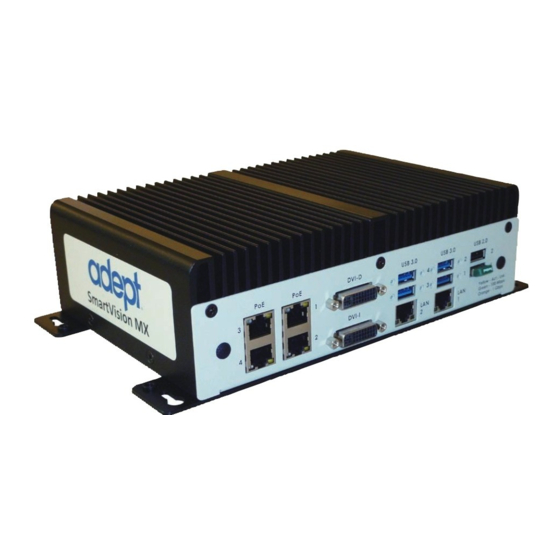
Chapter 4: Connectors and Indicators The SmartVision MX, shown in the following figures, can connect to many different peri- pherals. This section describes the connectors and indicators available. Camera Side Gigabit Ethernet DVI-D USB 3.0 USB 2.0 with PoE DVI-I Ethernet Figure 4-1. -
Page 20: Power/Io Side
Ethernet ports on the industrial PC. CAUTION: Do not connect the SmartVision MX directly to the internet. If the SmartVision MX is on a LAN that has Internet access, make sure there is a firewall between the LAN and the Internet in order to prevent unwanted and unauthorized network traffic from reaching the SmartVision MX. -
Page 21: Usb Ports
4.3 DVI- Ports To connect a monitor with a DVI connector: Connect the monitor to the DVI-I port on the SmartVision MX Connect the monitor to the DVI-D port on the SmartVision MX. Connecting a VGA monitor requires using the DVI-I port with a user-supplied VGA adapter. -
Page 23: Chapter 5: Operation
5.3 Checking the Licenses on the Dongle You can see what has been enabled on a dongle with the following procedure: 1. Turn on the SmartVision MX industrial PC and wait for it to finish booting. 2. Double-click the ACE icon on the desktop. -
Page 25: Chapter 6: Technical Specifications
Embedded Standard 7, 64 bit Hard Drive 64 GB SSD 6.2 Environmental Specifications The SmartVision MX must be shipped and stored in a temperature-controlled environment. Refer to the following table. Table 6-2. Environmental Specifications Ambient temperature 0° to 50° C (32° to 122° F) Storage and shipment temperature –25°... -
Page 26: Connections
One of these is used for the license dongle. DVI-D output DVI-I output RS232/RS485 port RS232 port 8 digital inputs up to 9 V tolerant 8 digital outputs 100 mA max @ 24 VDC SmartVision MX User’s Guide, 14362-000 Rev. B Page 26 of 30... -
Page 27: Chapter 7: Options
ACE PackXpert, the SmartController needs to have a motion license. 7.2 Mounting The SmartVision MX industrial PC can be ordered with brackets that let the user mount the industrial PC on top of a SmartController motion controller. SmartVision MX User’s Guide, 14362-000 Rev. B... - Page 30 OMRON ADEPT TECHNOLOGIES, INC. No. 438A Alexandra Road # 05-05/08 (Lobby 2), 4550 Norris Canyon Road, Suite 150, San Ramon, CA 94583 U.S.A. © OMRON Corporation 2016 All Rights Reserved. Alexandra Technopark, Tel: (1) 925-245-3400/Fax: (1) 925-960-0590 In the interest of product improvement,...
Need help?
Do you have a question about the SmartVision MX and is the answer not in the manual?
Questions and answers