
Related Manuals for HMS Anybus Communicator CAN PROFINET IRT 2.32


Summary of Contents for HMS Anybus Communicator CAN PROFINET IRT 2.32
- Page 1 A A n n y y b b u u s s ® ® C C o o m m m m u u n n i i c c a a t t o o r r ™ ™ C C A A N N P P R R O O F F I I N N E E T T ®...
- Page 2 HMS Industrial Networks reserves the right to modify its products in line with its policy of continuous product development. The information in this document shall therefore not be construed as a commitment on the part of HMS Industrial Networks and is subject to change without notice.
-
Page 3: Table Of Contents
Table of Contents Page Preface ..........................3 About This Document .......................3 Document history ......................3 Document Conventions .....................4 Description .......................... 5 Introduction ........................5 Data Exchange Model .......................6 PROFINET IRT Protocol ......................7 CAN Network Protocol ......................8 Installation......................... 13 Installation Overview ...................... 13 Connectors and Indicators .................... - Page 4 Technical Data ........................39 General Specifications..................... 39 CAN Interface ........................ 39 PROFINET IRT Interface ....................39 Licenses..........................40 SCM-1202-035 1.2 en-US Anybus ® Communicator ™ CAN PROFINET ® IRT (2.32) User Manual...
-
Page 5: Preface
Preface 3 (42) Preface About This Document This document describes how to install and configure the Anybus Communicator CAN PROFINET IRT (2.32) gateway. For additional related documentation and file downloads, please visit www.anybus.com/support. Document history Date Version Description 2017-02-23 First release 2017-11-22 Updated for new firmware 2019-04-11... -
Page 6: Document Conventions
This is a cross-reference within this document: Document Conventions, p. 4 This is an external link (URL): www.hms-networks.com This is additional information which may facilitate installation and/or operation. This instruction must be followed to avoid a risk of reduced functionality and/or damage to the equipment, or to avoid a network security risk. -
Page 7: Description
Description 5 (42) Description Introduction Anybus Communicator CAN PROFINET IRT (2.32) is designed to exchange data between a CAN subnetwork and a higher level network. The CAN protocol uses individually configurable frames, offering great flexibility. Through the configuration of CAN frames, the Anybus Communicator CAN will adapt to a predefined CAN subnetwork. -
Page 8: Data Exchange Model
Description 6 (42) Data Exchange Model 2.2.1 Overview The data exchanged on the CAN subnetwork and the data exchanged on the higher level network reside in the same internal memory in the Anybus Communicator CAN. In order to exchange data with the CAN subnetwork, the higher level network simply reads and writes data to memory locations that have been specified in Anybus Configuration Manager. -
Page 9: Profinet Irt Protocol
Description 7 (42) PROFINET IRT Protocol PROFINET is the open Industrial Ethernet standard for automation from PROFIBUS and PROFINET International. The PROFINET IRT device provides PROFINET IO Isochronous Real Time Communication. PROFINET makes a clear distinction between fast cyclical data, IO Data, and acyclical data, Record Data. -
Page 10: Can Network Protocol
Description 8 (42) CAN Network Protocol 2.4.1 General The CAN protocol is message-based and can exchange up to 8 bytes of data in each message. The protocol only acts as a data carrier, it is up to each application to define and interpret the data content of the messages. - Page 11 Description 9 (42) Fig. 5 Produce and Consume messages SCM-1202-035 1.2 en-US Anybus ® Communicator ™ CAN PROFINET ® IRT (2.32) User Manual...
- Page 12 Description 10 (42) 2.4.3 Protocol Building Blocks The following building blocks are used in Anybus Configuration Manager to describe the subnetwork communication. Group A group does not represent any specific device on the CAN subnetwork, it is only a means to structure the transactions that have been defined for the gateway in Anybus Configuration Manager.
- Page 13 Description 11 (42) 2.4.4 Control and Status Words The optional Control and Status Words can be used to control the startup mode of the Anybus Communicator CAN and to read the status of the CAN subnetwork. The Control Word is always mapped to the first two bytes of the output data area, and the Status Word to the first two bytes of the input data area, with the Least Significant Byte in the first byte (byte 0).
- Page 14 Description 12 (42) 2.4.5 Transaction Live List The optional Transaction Live List consists of a bit array where each bit corresponds to a transaction on the CAN subnetwork (bit 0 corresponds to transaction 1 etc.). A set bit indicates normal functionality. The bit is not set if the transaction is non-working or non-existent. The live list is mapped in the Input data area of the memory, either at the start of the area or directly after the Status word.
-
Page 15: Installation
Installation 13 (42) Installation This product contains parts that can be damaged by electrostatic discharge (ESD). Use ESD prevention measures to avoid damage. Installation Overview These are the basic steps for installing Anybus Communicator CAN gateways. Depending on the fieldbus network type there may also be configuration switches on the Anybus Communicator CAN that need setting. -
Page 16: Connectors And Indicators
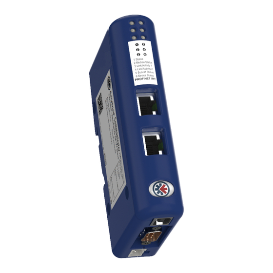
Installation 14 (42) Connectors and Indicators 3.2.1 External Parts Fig. 7 Overview LED indicators DIN rail mount Power connector CAN connector USB connector PROFINET IRT network interface DIN Rail Mounting The unit must be electrically grounded through the DIN rail for EMC compliance. Mount on DIN rail Hook the unit onto the upper lip of the rail and push gently downwards. - Page 17 Installation 15 (42) Pull the bottom end of the unit free of the rail and remove it. SCM-1202-035 1.2 en-US Anybus ® Communicator ™ CAN PROFINET ® IRT (2.32) User Manual...
-
Page 18: Can Interface
Installation 16 (42) CAN Interface The CAN network connector is located on the bottom of the unit. Signal 1 (male) CAN_L CAN_GND Shield CAN_GND CAN_H Fig. 9 CAN connector 1, 4, 8, 9 (reserved) PROFINET Interface The PROFINET IRT interface contains a dual port Ethernet switch with RJ45 type connectors. The two ports are labeled LAN 1 and LAN 2. -
Page 19: Led Indicators
Installation 17 (42) LED Indicators The LED indicators provide diagnostic information about data communication and status of the network interfaces as well as general device status. LED 1 to 4 PROFINET IRT network status LED 5 CAN network status LED 6 Device status Indication Meaning... -
Page 20: Configuration
Configuration 18 (42) Configuration Configuration Overview Device Description Files A device description file contains a description of a network device, its functions, object dictionary implementations, etc., and is used when configuring the network interface. The device description file can be referred to as a DDF, EDS, GSD, etc., depending on the type of network. The latest versions of the device description files can be downloaded from www.anybus.com/support. -
Page 21: Network Configuration
Configuration 19 (42) Network Configuration To be able to communicate over Ethernet, the PROFINET network interface needs a valid TCP/IP configuration. This section explains some basic concepts and describes how to configure the TCP/IP settings using the IPconfig software tool. When Ethernet communication has been established the TCP/IP settings can also be changed from the web interface. - Page 22 4.2.2 TCP/IP Configuration Installing the IPconfig Utility IPconfig is a Windows-based tool for configuration of TCP/IP settings in HMS devices. The tool will detect all compatible and active HMS devices on the local network. Download IPconfig from www.anybus.com/support. Unpack the contents of the zip archive and run the installer program.
- Page 23 Configuration 21 (42) Ethernet Configuration To change the IP settings for a device, double-click on the entry in the main window or right-click on it and select Configuration. Fig. 14 Ethernet configuration Enter static IP settings as required, or select DHCP if using dynamic IP addressing. Do not enable DHCP if there is no DHCP server available on the network.
- Page 24 Configuration 22 (42) IPconfig Settings Additional settings for IPconfig can be accessed by clicking on Settings. Fig. 15 IPconfig settings Network Interface Check this option to select a specific network interface to use when scanning for devices from a computer which has more than one interface. If this option is left unchecked, all available networks will be scanned.
-
Page 25: Web
Configuration 23 (42) Web Pages Network configuration settings and status of the PROFINET IRT network interface can be accessed by pointing a web browser to the IP address of the interface. Module Overview Fig. 16 Overview tab Provides basic information about the Anybus Communicator CAN including the serial number and the installed firmware version. -
Page 26: Anybus Configuration Manager
Anybus Configuration Manager 24 (42) Anybus Configuration Manager Main Window Fig. 19 Anybus Configuration Manager - Communicator CAN 1: Menus and Toolbar The most common menu commands can also be carried out by clicking on a button in the toolbar. Moving the mouse cursor over a toolbar button will display a tooltip explaining its function. -
Page 27: Basic Settings
Anybus Configuration Manager 25 (42) Basic Settings For more detailed explanations of each configuration setting, see the help texts in the Information Window. 5.2.1 Project Used to store project information such as project name, project creator, version and description. 5.2.2 Network Settings General During startup the fieldbus interface is initialized to fit the configuration created in Anybus... - Page 28 Anybus Configuration Manager 26 (42) 5.2.4 Subnetwork Settings Settings for the CAN subnetwork. Parameter Comment Values Bit Rate Select the bit rate on the CAN subnetwork. 20 kbit/s 50 kbit/s 100 kbit/s 125 kbit/s 200 kbit/s 250 kbit/s 500 kbit/s 800 kbit/s 1000 kbit/s Bus Off Action...
-
Page 29: Profinet Asset Management
PROFINET Asset Management 27 (42) PROFINET Asset Management Asset Management Record With the asset management record functionality data about the assets available on a non PROFINET network can be recorded and read out over a PROFINET network. Together with the Identification & Maintenance data functionality an extensive registration of devices and machines is possible, even in facilities where the devices are not installed in the PROFINET environment. -
Page 30: Supported File Formats
PROFINET Asset Management 28 (42) Record Data Data about the assets on the non PROFINET network is recorded and stored in an XML file or an binary file. Read Data Each time an instance is requested the asset management data is read out over the PROFINET network. -
Page 31: Xml Based Asset Management
PROFINET Asset Management 29 (42) XML Based Asset Management 6.5.1 Creating the Asset Management XML File Creating the asset management XML file: List all assets and their corresponding data on the non PROFINET network. Create an XML file that include one asset management record for each asset. Repeat all the attributes after each other. - Page 32 PROFINET Asset Management 30 (42) Attribute Name and Data Format Data Format Attribute Name Description AM info Type Unsigned 8 The value can be set in either of two formats, 0x12 or 18. Location Type AM Type Identification Unsigned 16 The value can be set in either of two formats, 0x1234 or IM Hardware Revision 4660.
- Page 33 PROFINET Asset Management 31 (42) 6.5.4 Asset Management XML File Structure Example The code example presented below can be used as a guide when creating the asset management XML file. Fig. 21 Asset management XML file structure example SCM-1202-035 1.2 en-US Anybus ®...
-
Page 34: Binary Based Asset Management
PROFINET Asset Management 32 (42) Binary Based Asset Management 6.6.1 Creating the Asset Management Binary File Creating the asset management binary file: List all assets and their corresponding data on the non PROFINET network. Create an Binary file that include a asset management record for each asset. Repeat all the attributes after each other. - Page 35 PROFINET Asset Management 33 (42) 6.6.4 Binary Instance Data Each instance consists of a series of attributes and their respective data. Attribute Description Each attribute is described by one entry. Data type Comment Attribute Description Byte number Attribute number UINT8 Attribute number of the data being described.
- Page 36 PROFINET Asset Management 34 (42) Attribute Name and Data Format Supported attribute names and data formats. Attribute Name and Data Format Data Format Description Attribute Name AM info Type Unsigned 8 The value is set as one byte value. Location Type AM Type Identification Unsigned 16 The value is set with two bytes, little-endian format.
- Page 37 PROFINET Asset Management 35 (42) 6.6.5 Asset Management Binary File Example The binary file structure example presented below can be used as a guide when creating the asset management binary file. Only instance 1 is supported. For instance 1, only attribute 1 and 2 are defined. Fig.
-
Page 38: Uploading The Asset Management File To The Ftp Server
PROFINET Asset Management 36 (42) Uploading the Asset Management File to the FTP Server Use Windows Explorer or a standard FTP client to transfer the asset management file to the FTP server. When the superposed parameter channel function is enabled, transfer the asset management file via a PLC connected to the network where the gateway is installed. - Page 39 PROFINET Asset Management 37 (42) Fig. 24 Application folder with an asset_mgmt.xml file Open the application folder and save the asset management file, XML or Binary file, in the folder. SCM-1202-035 1.2 en-US Anybus ® Communicator ™ CAN PROFINET ® IRT (2.32) User Manual...
- Page 40 This page intentionally left blank...
-
Page 41: A Technical Data
Appendix A: Technical Data 39 (42) Technical Data General Specifications Model name Anybus Communicator CAN PROFINET IRT (2.32) Order code AB7328 Dimensions (L x W x H) 120 x 75 x 27 mm 150 g Weight Operating temperature -25 to +55 °C (IEC 60068-2-1 and IEC 60068-2-2) Storage temperature -40 to +85 °C (IEC 60068-2-1 and IEC 60068-2-2) Humidity range... -
Page 42: B Licenses
Appendix B: Licenses 40 (42) Licenses This product includes software developed by Carnegie Mellon, the Massachusetts Institute of Technology, the University of California, and RSA Data Security: Copyright 1986 by Carnegie Mellon. Copyright 1983,1984,1985 by the Massachusetts Institute of Technology Copyright ©... - Page 43 This page intentionally left blank...
- Page 44 © 2019 HMS Industrial Networks Box 4126 300 04 Halmstad, Sweden info@hms.se SCM-1202-035 1.2 en-US / 2019-04-12 / 12861...
Need help?
Do you have a question about the Anybus Communicator CAN PROFINET IRT 2.32 and is the answer not in the manual?
Questions and answers