Table of Contents
Advertisement
Quick Links
Advertisement
Table of Contents

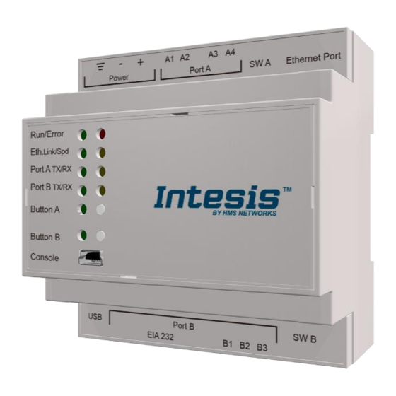
Summary of Contents for HMS Intesis KNX Series
- Page 1 USER MANUAL Issue date: 05/2018 r1.2 ENGLISH...
- Page 2 HMS Industrial Networks reserves the right to modify its products in line with its policy of continuous product development. The information in this document shall therefore not be construed as a commitment on the part of HMS Industrial Networks and is subject to change without notice.
- Page 3 Modbus RTU and/or Modbus TCP enabled monitoring and control systems. ORDER CODE LEGACY ORDER CODE INMBSKNX1000000 IBMBSKNX1000000 INMBSKNX2500000 IBMBSKNX2500000 INMBSKNX6000000 IBMBSKNX6000000 INMBSKNX1K20000 IBMBSKNX1K20000 INMBSKNX3K00000 IBMBSKNX3K00000 © HMS Industrial Networks S.L.U - All rights reserved https://www.intesis.com This information is subject to change without notice 3 / 18...
-
Page 4: Table Of Contents
Modbus RTU ........................... 11 Connection to the configuration tool ....................11 5 Set-up process and troubleshooting ...................... 12 Pre-requisites ..........................12 Intesis MAPS. Configuration & monitoring tool for Intesis KNX series .......... 12 5.2.1 Introduction ..........................12 5.2.2 Connection ..........................12 5.2.3... -
Page 5: Description
Integration of KNX TP-1 devices or installations into Modbus RTU Master or Modbus TCP Clients control and monitoring systems © HMS Industrial Networks S.L.U - All rights reserved https://www.intesis.com This information is subject to change without notice 5 / 18... -
Page 6: Functionality
Number of Modbus Number of Modbus Master Master devices devices supported by the device Up to 6 TCP connections © HMS Industrial Networks S.L.U - All rights reserved https://www.intesis.com This information is subject to change without notice 6 / 18... -
Page 7: Knx Interface
2 KNX interface In this section, a common description for all Intesis KNX series gateways is given from the point of view of KNX system, which is called from now on external system. The Modbus system is also called from now on internal system. -
Page 8: Modbus Interface
The Modbus address map is fully configurable; any point in the Intesis can be freely configured with the desired Modbus register address. © HMS Industrial Networks S.L.U - All rights reserved https://www.intesis.com This information is subject to change without notice... -
Page 9: Points Definition
Modbus function codes 3 and 4 (read holding/input registers). Read/Write 0: Read 1: Write 2: Read / Write © HMS Industrial Networks S.L.U - All rights reserved https://www.intesis.com This information is subject to change without notice 9 / 18... -
Page 10: Connections
Connect a USB storage device (not a HDD) if required. Check the user manual for more information. Ensure proper space for all connectors when mounted (see section 7). © HMS Industrial Networks S.L.U - All rights reserved https://www.intesis.com This information is subject to change without notice... -
Page 11: Powering The Device
Ethernet: Using the Ethernet port of Intesis. • USB: Using the console port of Intesis, connect a USB cable from the console port to the PC. © HMS Industrial Networks S.L.U - All rights reserved https://www.intesis.com This information is subject to change without notice... -
Page 12: Set-Up Process And Troubleshooting
® Intesis MAPS is a Windows compatible software developed specifically to monitor and configure Intesis KNX series. The installation procedure and main functions are explained in the Intesis MAPS User Manual. This document can be downloaded from the link indicated in the installation sheet supplied with the Intesis device or in the product website at www.intesis.com... -
Page 13: Configuration Tab
More information on each parameter and how to configure it can be found in the Intesis MAPS user manual. Figure 5.3 Intesis MAPS Signals tab © HMS Industrial Networks S.L.U - All rights reserved https://www.intesis.com This information is subject to change without notice... -
Page 14: Sending The Configuration To Intesis
Console viewer for general information about communications and the gateway status and finally a Signals Viewer to simulate the BMS behavior or to check the current values in the system. © HMS Industrial Networks S.L.U - All rights reserved https://www.intesis.com This information is subject to change without notice... - Page 15 User Manual r1.2 eng Figure 5.5 Diagnostic More information about the Diagnostic section can be found in the Configuration Tool manual. © HMS Industrial Networks S.L.U - All rights reserved https://www.intesis.com This information is subject to change without notice 15 / 18...
-
Page 16: Set-Up Procedure
Intesis and the KNX and/or Modbus devices, check that those are operative: check the baud rate, the communication cable used to connect all devices and any other communication parameter. © HMS Industrial Networks S.L.U - All rights reserved https://www.intesis.com This information is subject to change without notice... -
Page 17: Electrical & Mechanical Features
ON: 120 Ω termination active Switch B Off: 120 Ω termination inactive (SWB) Position 2-3: ON: Polarization active Off: Polarization inactive © HMS Industrial Networks S.L.U - All rights reserved https://www.intesis.com This information is subject to change without notice 17 / 18... -
Page 18: Dimensions
Recommended available space for its installation into a cabinet (wall or DIN rail mounting), with space enough for external connections. 100 mm (h) 130 mm (d) 100 mm (w) © HMS Industrial Networks S.L.U - All rights reserved https://www.intesis.com This information is subject to change without notice 18 / 18...


Need help?
Do you have a question about the Intesis KNX Series and is the answer not in the manual?
Questions and answers