Table of Contents
Advertisement
Quick Links
Advertisement
Table of Contents

Related Manuals for HMS IXXAT CANbridge


Summary of Contents for HMS IXXAT CANbridge
- Page 1 CANbridge CAN-to-CAN Gateway USER MANUAL 4.01.0120.20000 2.1 en-US ENGLISH...
- Page 2 HMS Industrial Networks reserves the right to modify its products in line with its policy of continuous product development. The information in this document shall therefore not be construed as a commitment on the part of HMS Industrial Networks and is subject to change without notice.
-
Page 3: Table Of Contents
Table of Contents Page User Guide ........................... 3 Related Documents ......................3 Document History ......................3 Conventions........................4 Safety Instructions ......................5 Information on EMC ......................5 General Safety Instructions ....................5 Scope of Delivery ........................ 6 Product Description and Features..................6 Installation........................... 7 Connectors Aluminium Version...................7 Connectors Industrial DIN Rail Version .................9 Configuration........................ - Page 4 11 Disposal..........................23 Regulatory Compliance ..................... 25 EMC Compliance (CE) ..................... 25 FCC Compliance Statement ....................25 Disposal and recycling..................... 26 4.01.0120.20000 2.1 en-US CANbridge User Manual...
-
Page 5: User Guide
Revised and edited in new design. June 2019 Layout changes, new disclaimer 1.2.1 Trademark Information Ixxat ® is a registered trademark of HMS Industrial Networks. All other trademarks mentioned in this document are the property of their respective holders. 4.01.0120.20000 2.1 en-US CANbridge User Manual... -
Page 6: Conventions
This is a cross-reference within this document: Conventions, p. 4 This is an external link (URL): www.hms-networks.com Safety advice is structured as follows: Cause of the hazard! Consequences of not taking remediate action. -
Page 7: Safety Instructions
► Protect product from fire. ► Do not paint the product. ► Do not modify or disassemble the product. Service must be carried out by HMS Industrial Networks. ► Store products in dry and dust-free place. 4.01.0120.20000 2.1 en-US CANbridge User Manual... -
Page 8: Scope Of Delivery
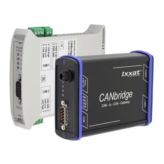
Scope of Delivery 6 (28) Scope of Delivery Included in scope of delivery: • CANbridge • User Manual • CD with download tool CANBcfg.exe and VCI Installation Guide • configuration cable • aluminium and automotive version: power supply cable Product Description and Features The CANbridge is a universal, intelligent CAN topology component, that allows the coupling of two CAN networks, also with different bit rates or frame formats. -
Page 9: Installation
Installation 7 (28) Installation Connectors Aluminium Version Industrial and automotive version are available as aluminium version. Fig. 2 Aluminium version Power supply Serial interface RS232 CAN 1 CAN 2 5.1.1 Power Connector The CANbridge is protected against polarity reversal, under- and over-voltage. •... - Page 10 Installation 8 (28) 5.1.2 CAN Connectors The signals of CAN 1 and CAN 2 are connected to D-Sub 9 connectors. In automotive version CAN 2 is available as CAN low speed. Pin Allocation D-Sub 9 Connector Pin no. Signal CAN connector, D-Sub 9 —...
-
Page 11: Connectors Industrial Din Rail Version
Installation 9 (28) Connectors Industrial DIN Rail Version Fig. 3 Industrial DIN rail version Power supply CAN 1 Serial interface RS232 CAN 2 Pins are labelled continuously on the device, starting with PE, labelled as 1. 5.2.1 Power Connector The CANbridge is protected against polarity reversal, under- and over-voltage. •... - Page 12 Installation 10 (28) 5.2.2 CAN Connectors Pin Allocation D-Sub 9 Connector, CAN 1 and CAN 2 CAN 1 connector Pin no. Signal CAN-High CAN-Low 5.2.3 Configuration Connector The serial interface RS232 is used to configure the CANbridge. The signals are connected to a D- Sub 9 connector.
-
Page 13: Configuration
Configuration 11 (28) Configuration The Windows console program CANBcfg.exe is available for the configuration the CANbridge (included on delivery CD). Starting and Operating the Download Tool CANBcfg The program is operated via call parameters. ► Make sure that CANBcfg.exe is installed locally with writing permission. ►... -
Page 14: Creating The Configuration
Configuration 12 (28) Creating the Configuration 6.2.1 Creating a Template with Download Tool Start CANBcfg.exe (see Starting and Operating the Download Tool CANBcfg, p. 11). ► Enter parameter -g (CANBcfg —g). ► → File template.clg is created. ► Open the file template.clg with the text editor. ►... - Page 15 Configuration 13 (28) 6.2.2 Adjusting the General Settings [General] The TemplateVersion shows the version number of the ASCII file structure, used for compatibility check and must not be changed. Repeater Mode Parameter Description Repeater Mode deactivated. RepeaterFunctionality = no Messages are transmitted unchanged. RepeaterFunctionality = yes Entries in FrameFormat and CANGatewayTable are ignored.
- Page 16 Automatic Baud Rate Detection Sequence, p. Setting of Bus Timing Register HMS Industrial Networks recommends using the predefined standard baud rates. If user defined baud rates are used, make sure that the entered values are valid. If the baud rate is set with the bit timing register BTR0 and BTR1 of the controller, baud rates that are not defined by CiA can be used.
- Page 17 Configuration 15 (28) Frame Format Parameter Description Standard (11 bit identifier) FrameFormat = std FrameFormat = ext Extended (29 bit identifier) Mapping Table Parameter Description Mapping tables of [CAN1GatewayTable] resp. UseGatewayTable = yes [CAN2GatewayTable] are used. Mapping tables are not used, all messages are transmitted UseGatewayTable = no unchanged.
- Page 18 Configuration 16 (28) If frame format extended is translated in standard: • 29 bit identifiers on the left • 11 bit identifiers on the right • 128 entries possible All possible identifiers are listed in the template, mapped 1 to 1: If configuration with only 128 possible entries is used, delete surplus entries.
-
Page 19: Load Configuration To Device
Configuration 17 (28) Load Configuration to Device ► Connect the serial interface RS232 of the CANbridge and the serial interface of the computer with a null modem cable. Call CANBcfg.exe with parameter —a <filename> —i<name> (e.g. CANBcfg —a ► myconfig.cfg —iCOM7). →... -
Page 20: Show Current Configuration
Configuration 18 (28) Show Current Configuration ► To read the current configuration, add parameter —v (e.g CANbcfg —v). → File and configuration name are displayed. Fig. 6 Show configuration Standard Configuration Standard configuration of CANbridge: • automatic baud rate detection activated •... -
Page 21: Configuration Example
Configuration 19 (28) Configuration Example The example has the following configuration: • CAN 1 has standard frame format. • CAN 1 baud rate is 800 kBit/s. • CAN 1 and CAN 2 mapping tables are used. • CAN 2 has extended frame format. •... -
Page 22: Operation
Operation 20 (28) Operation Fig. 7 LED arrays industrial rail version and automotive version Power LED CAN 1 LED CAN 2 LED SER LED (automotive: COM LED) Automatic Baud Rate Detection Sequence During the automatic baud rate detection CAN 1 LED (3), CAN 2 LED (4) and PWR LED (1) indicate the status. -
Page 23: Ser/Com Led
Additional Components 21 (28) SER/COM LED In the industrial DIN rail version the LED is labeled SER, in the automotive version COM. LED state Description Comments Green flashing Message received or transmitted without errors Red flashing Message received or transmitted with errors Additional Components CAN Bus Termination... -
Page 24: Technical Data
Technical Data 22 (28) Technical Data CAN controller 2 x NXP (Philips) SJA 1000 Texas Instruments SN65HVD251 CAN transceiver (high-speed) CAN transceiver (low-speed) NXP (Philips) TJA1054 Microcontroller Fujitsu MB90F543, 16 MHz RAM/Flash 6 kByte/128 kByte Max. number of CAN bus nodes 120 (high-speed), 32 (low-speed) CAN bus termination resistor none (high-speed) -
Page 25: Support/Return Hardware
23 (28) Support/Return Hardware Support/Return Hardware Observe the following information in the support area on www.ixxat.com: • information about products • FAQ lists • installation notes • updated product versions • updates 10.1 Support For problems or support with the product request support at www.ixxat.com/support. ►... - Page 26 This page intentionally left blank...
-
Page 27: A Regulatory Compliance
Phone +1 312 829 0601 Any changes or modifications not expressly approved by HMS Industrial Networks could void the user's authority to operate the equipment. This equipment has been tested and found to comply with the limits for a Class A digital device, pursuant to part 15 of the FCC Rules. -
Page 28: Disposal And Recycling
When this product reaches its end of life, contact local authorities to learn about disposal and recycling options, or simply drop it off at your local HMS office or return it to HMS. For more information, see www.hms-networks.com. - Page 29 This page intentionally left blank...
- Page 30 © 2019 HMS Industrial Networks Box 4126 300 04 Halmstad, Sweden info@hms.se 4.01.0120.20000 2.1 en-US / 2019-06-25 / 13800...
Need help?
Do you have a question about the IXXAT CANbridge and is the answer not in the manual?
Questions and answers