Hardi HC5500 Instruction Book
Hide thumbs
Also See for HC5500:
- Instruction book (76 pages) ,
- Service manual (45 pages) ,
- Installation manual (8 pages)

Related Manuals for Hardi HC5500


Summary of Contents for Hardi HC5500
- Page 1 CONTROLLER HC5500 Original Instruction book - SW 4.XX 67000400-201 - Version 2.01 GB - 10.2008 www.hardi-international.com...
- Page 2 Illustrations, technical information and data in this book are to the best of our belief correct at the time of printing. As it is HARDI INTERNATIONAL A/S policy permanently to improve our products, we reserve the right to make changes in design, features, accessories, specifications and maintenance instructions at any time and without notice.
-
Page 3: Table Of Contents
Menu 2.2.2 Foam Marker (optional) ................................ 32 Menu 2.2.3 Dual line (optional) .................................. 32 Menu 2.3 VRA/Remote control ......................33 Variable Rate Application (VRA) / Remote / HARDI AutoSectionControl ................. 33 Menu 2.4 Set clock ..........................34 How to set clock ........................................34... - Page 4 Table of Contents Menu 2.5 Alarms ..........................35 How to set up alarms ......................................35 Menu 2.5.6 Audio level ....................................35 Menu 2.6 Register names ........................36 How to name the registers ................................... 36 Menu 2.6.XX Copy name ....................................36 7 - Menu 3 Calibration Menu 3.1 Speed calibration .........................37 Menu 3.1.1 Sprayer ......................................
- Page 5 Table of Contents 9 - Menu 5 Logbook Menu 5.1 Print .............................61 What you can print ......................................61 Menu 5.2 Data dump ...........................62 How to dump data ......................................62 10 - Mistblowers Soft keys ..............................63 General info ..........................................63 Unit Canopy Row ........................................ 63 How to control canopy ....................................
- Page 6 Table of Contents...
-
Page 7: Ce Declaration
1 - CE Declaration Declaration of conformity Manufacturer: Importer: HARDI INTERNATIONAL A/S Helgeshøj Allé 38 DK 2630 Taastrup DENMARK declare that the following product; Model no. Serial no. A. was manufactured in conformity with the provisions in the COUNCIL DIRECTIVE of 22 June 1998 on mutual... - Page 8 1 - CE Declaration...
-
Page 9: Safety Notes
€ Keep children away from the equipment. € If any portion of this instruction book remains unclear after reading it, contact your HARDI dealer for further explanation before using the equipment. € Turn electrical power off before connecting and disconnecting the display and transducers, servicing or using a battery charger. - Page 10 2 - Safety notes...
-
Page 11: Description
3 - Description General info General info The HARDI Controller 5500 is for use in agricultural and horticultural production. The Controller permits automatic control of application rate. Main components are: • Controller • Spray Box • Junction box (on sprayer) •... -
Page 12: Glossary And Pictorial Symbols
Glossary and pictorial symbols Controller HARDI Controller 5500 with display. Spray Box HARDI Control Box with all basic control functions. Junction box Box on the sprayer for Controller and Control Box. Jobcom Box on the sprayer with SafeTrack computer and/or AutoSectionControl. -
Page 13: Pressure Based Regulation (Optional Equipment)
SafeTrack and IntelliTrack SafeTrack and IntelliTrack are a steering mechanism for the HARDI sprayers. When using a track system, sprayer stability is a common concern. Many factors influence the sprayer and conditions where the sprayer might tip over have to be dealt with. -
Page 14: System Description
3 - Description System description Overall description 1. Controller 2. Spray Box 3. To 12 Volt power supply 4. Multi wire plug and cable 5. Junction box (on sprayer) 6. Jobcom (optional) 7. Flow transducer 8. Speed transducer 9. Tank contents transducer (optional) 10. -
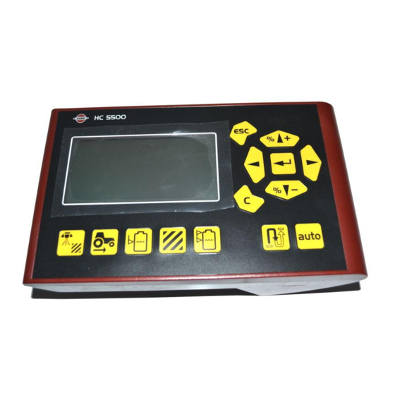
Page 15: Keys
3 - Description Keys General key description The HC 5500 controller buttons are placed in three groups; navigation keys, shortcut keys, distance key and the auto key. The shortcut keys can be used for the following: Short press: Displays volume sprayed for the active register. Long press: Enter Register select (menu 1.3.1 Register select). - Page 16 3 - Description The navigation keys are initially used for set up in the menu system and working screen. To navigate the menus then press to start this process. Then bottons can be used for the following: Pressing will: • Scroll up, •...
-
Page 17: General Keystrokes, Example: Tank Contents
3 - Description General keystrokes, Example: Tank contents The following is a general description in keystrokes and display readout. The following example, of changing the Tank contents value, is used to illustrate this. Try it! The same method is used in all the menus. μ... -
Page 18: Keystroke Menu Tree
3 - Description Keystroke menu tree The first steps to choose a menu are shown below. Press to proceed into the menu. See the relevant section in the book. Press and hold to exit the menu system. 5 Logbook 5.2 Data dump 5.1 Print 4 Toolbox 4.7 Emergency track... -
Page 19: System Setup
4 - System setup Tractor installation Control units Find a suitable place in the tractor’s cabin to secure the control units from movement. Best recommended placement is to the right of the driver seat. The supplied bracket will fit most tractors. Threaded mounting holes may be hidden behind front corner cover. -
Page 20: Power Supply
If having a tractor with another power connector it is necessary to disassemble connector and fit it to the actual tractor connector. Use the HARDI Electric distribution box (Ref. no. 817925) if the tractor has a doubtful wiring. CIGAR CONNECTOR... -
Page 21: Speed Transducer For Tractor
Note the following if the Foot pedal remote is to be fitted. Remote ON/OFF switch has to be activated from the extended menu at installation. The HARDI Service centre does this. The speed/switch harness (A) is connected to the Controller/Terminal. -
Page 22: Initial System Start-Up
4 - System setup Initial system start-up When connecting the 39 pin plug from the sprayer, then note the one- way brackets inside the connector and connector plug. There are two different brackets to designate connector plug for respectively liquid (1) and hydraulic (2) boxes.ATTENTION! The Controller/Terminal should be protected from moisture and should be removed when not in use, if the tractor does not have a cabin. -
Page 23: Daily Settings
4th line. These datas should reflect the sprayer it is mounted to - if not, please contact your local HARDI dealer to correct this. 3. If the sprayer is equipped with LookAhead and this is enabled in BOOM: XX.X m... -
Page 24: Check Lookahead Pressure Regulation At Speed Change
4 - System setup Check LookAhead pressure regulation at speed change 1. Press button for pressure regulation on the Controller. Check that fly-leg icon appears in upper left corner of the display. 2. Go to menu [4.6 speed simulation]. Key in e.g. 9 km/h and press to use the value. -
Page 25: Check Lookahead Pressure Regulation At Section Change
4 - System setup Check LookAhead pressure regulation at section change 1. Go to menu [4.6 speed simulation]. Key in 6 km/h and press use the value. 2. Press to leave to workscreen. 3. Press button for pressure regulation on the Controller. Check that fly-leg icon appears in upper left corner of the display. - Page 26 4 - System setup...
-
Page 27: Menu 1.1 Volume Rate
5 - Menu 1 Daily settings 5 - Menu 1 Daily settings Menu 1.1 Volume rate How to change the volume rate The volume rate can be changed by: 1. Setting the desired rate in the Controller. 2. Manually raising or lowering the pressure via the Spray Box. 3. -
Page 28: Menu 1.2 Tank Contents
5 - Menu 1 Daily settings Menu 1.2 Tank contents To change the displayed Tank contents Shortcut Press and hold until menu [1.2 TANK CONTENTS] is shown. The maximum size of the tank is displayed TANK CONTENTS XXXX L Press again and the tank contents maximum value is shown. -
Page 29: Menu 1.3 Select Register
5 - Menu 1 Daily settings Menu 1.3 Select register Menu 1.3.1 Register readout and selection Register 1 to 98 can be used for individual areas. Register 99 is a tally of register trips 1 to 98. They are identified with a 1.3.1 number and it is also possible to name them. - Page 30 5 - Menu 1 Daily settings...
-
Page 31: Menu 2 Setup
6 - Menu 2 Setup Menu 2.1 Display readout General info The following menu explanations assume you have mastered the general keystrokes and you can “find your way” to the specific menu. If this is not so, please re-read section “Keys”. Menu 2.1.5 Work rate It is possible to freely choose which function is to be shown on the 3rd or 4th line of the display. -
Page 32: Menu 2.2 Auto Functions
Menu 2.2.2 Foam Marker (optional) The Controller can be set to operate the HARDI Foam marker automatically through the main ON/OFF valve. When the main ON/OFF is ON, it will automatically start the Foam marker. Furthermore, the Foam marker can be set for up and back spraying or race-track (round and round) spraying. -
Page 33: Menu 2.3 Vra/Remote Control
• 2400 baud • 1200 baud μ ATTENTION! The COM port may have to be set up in the extended menu. Contact your HARDI service centre. μ ATTENTION! Use of HARDI AutoSectionControl requires a sprayer equipped with JobCom computer. If in doubt... -
Page 34: Menu 2.4 Set Clock
6 - Menu 2 Setup Menu 2.4 Set clock How to set clock If the Controller prompts for date and time, [Set clock to enable register]: This must be done before the Controller is put into operation for the first time, otherwise no start and stop time will be recorded in the registers. -
Page 35: Menu 2.5 Alarms
6 - Menu 2 Setup Menu 2.5 Alarms How to set up alarms Six different alarms can be set up. Choices are listed as follows. DISPLAY TEXT NOTES 2.5.1 [2.5.1 Volume rate] Suggested setting is 10% [2.5.2 Tank contents] Measured in Litres ALARMS [2.5.3 Spray pressure] High/low pressure... -
Page 36: Menu 2.6 Register Names
6 - Menu 2 Setup Menu 2.6 Register names How to name the registers If desired, the registers can be given names. Once set up, a name can be copied and edited. Press to toggle between [Yes] or [No]. Press if the name can not be copied or edited. -
Page 37: Menu 3 Calibration
7 - Menu 3 Calibration Menu 3.1 Speed calibration Menu 3.1.1 Sprayer The calibration process is the same for each sensor type. In the following example a “speed sensor on sprayer“ is used. 3.1.1 Shortcut 1. Press SPEED CALIBRATION until menu [3.1.1 Sprayer] is shown. Sprayer It is possible to connect the speed sensor at different locations. -
Page 38: Menu 3.1.1.1 Constant
7 - Menu 3 Calibration Menu 3.1.1.1 Constant The theoretical speed constant, pulses per unit (PPU), is the distance in metre on the circumference of the wheel between holes (A) (or 3.1.1.1 protrusions / magnets (B)) that the speed sensor records. CONSTANT XX.XXX PPU Menu 3.1.1.2.1 Practical... -
Page 39: Menu 3.2 Flow Calibration
7 - Menu 3 Calibration Menu 3.2 Flow calibration Which method to use The flow transducer can be calibrated theoretically or with two practical methods. The practical methods are preferred. Calibration is done with clean water. The Flow Tank method is time consuming, but is more accurate than the Flow Nozzle method. -
Page 40: Menu 3.2.2 Nozzle Method
2. Go to menu [3.2.2 Nozzle method]. The display will then show the individual nozzle output per minute. FLOW CALIBRATION Close end nozzle 3. Using a HARDI calibration jug, check the actual nozzle output per minute. It is recommended that an average of several nozzles be 3.2.2 taken. -
Page 41: Menu 3.2.4 Circulation
The following is only relevant for sprayers equipped with circulation liquid system with 2 flowmeters. The circulation type liquid system has 3.2.4.1 to be set up from the Extended menu at installation. The HARDI Service centre does this. CIRCULATION Flow constant See menu [3.2 Flow calibration] for calibration of “Flow 1”. -
Page 42: Menu 3.3 Boom
7 - Menu 3 Calibration Menu 3.3 Boom Menu 3.3.1 Width Use the navigation keys to enter boom width. Press to confirm. 3.3.1 XX.X m Menu 3.3.2 Number of sections Use the navigation keys to set number of boom sections. Press to confirm. -
Page 43: Menu 3.4 Regulation Constant
7 - Menu 3 Calibration Menu 3.4 Regulation constant Regulation constant The sensitivity of pressure regulation valve can be adjusted. The goal is to find a value where the regulation does not overshoot the set point, but slows down and stops right before the set point. Increasing the regulation constant will give a faster response on the pressure regulation valve. -
Page 44: Menu 3.5 Tank Gauge
Menu 3.5 Tank gauge General info This menu item is only present if the HARDI Tank Gauge is fitted. For increased accuracy it is recommended to do the flow calibration [3.2] before proceeding. Present accuracy is up to +/- 25 litre. This is at the widest liquid surface area in the tank. The smaller the liquid surface area, the more accurate the readout. -
Page 45: Menu 3.5.2 Total
7 - Menu 3 Calibration Menu 3.5.2 Total Calibration of the HARDI Tank Gauge is necessary to take in account height of hitch point on the tractor and tyre mounting. Avoiding this 3.2.1 may result an inaccurate calculation of the tank contents. - Page 46 . Actual volume is the volume filled with the calibrated flowmeter. 11. Press TOTAL STEP . The new custom gauge table is calculated and the calibration of the HARDI Tank Gauge is finished. Emptied XXXX L...
-
Page 47: Menu 3.6 Track
7 - Menu 3 Calibration Menu 3.6 Track General info There is no standard setting for the Track set up. The Track needs to be adjusted for different kinds of tractors, the sprayer and spraying practices and can only be found under the actual conditions. For example;... -
Page 48: Menu 3.6.1 Track Width
7 - Menu 3 Calibration Menu 3.6.1 Track width Here the track width can be entered. The track is measured from right side tyre centre to left side tyre centre of the sprayer wheels. It is 3.6.1 important that the right track width is entered. The controller will calculate the speed to the centre of machine and not the speed of the wheel. -
Page 49: Menu 3.6.5 Alignment Offset
7 - Menu 3 Calibration Menu 3.6.5 Alignment offset Here the fine tuning of tractor and sprayer alignment is done. This is to compensate if the front potentiometer is placed offset to the centreline 3.6.5 when the sprayer is attached. Note +/- can be changed with ALIGNMENT OFFSET, Factory setting: 0 %... -
Page 50: Emergency Track
7 - Menu 3 Calibration 5. Press and hold the manual track button (11) to the direction indicated by the arrow in the display. Display will show a counting 3.6.6 percentage ending with an “OK” when gain is found. FINDING GAIN Press —>... -
Page 51: Menu 3.7 Lookahead
7 - Menu 3 Calibration Menu 3.7 LookAhead Menu 3.7.X LookAhead calibration At start-up of the HC 5500 user is promted for a nozzle choice. If the selected nozzle holds no LookAhead calibration in the HC 5500 ISO XXXX memory, it will need to be calibrated. Press to enable “auto”... - Page 52 μ ATTENTION! To calibrate, the speed must exceed the minimum speed set in the controller memory. If minimum driving speed is set too high, please contact your local HARDI dealer. μ ATTENTION! If all section valves are turned off then LookAhead is standby. When turning single sections off, e.g. in wedge shaped fields, then last valve must be turned off by using the main on/off.
-
Page 53: Menu 4 Toolbox
8 - Menu 4 Toolbox Menu 4.1 Measure Trip meter This is a simple electronic trip meter. You can measure distance. If the implement width is entered in menu [4.1.3 Working width], area can also be measured in menu [4.1.2 Area]. to clear the value. -
Page 54: Menu 4.2 Service Intervals
8 - Menu 4 Toolbox Menu 4.2 Service intervals Menu and intervals Service intervals and a nozzle check are programmed into the Controller. This makes it easier for the operator to remember the service intervals. From the factory, the Controller is set up with three service and a nozzle check reminder. Menu &... -
Page 55: Menu 4.3 Stop Watch
8 - Menu 4 Toolbox Menu 4.3 Stop watch Use as timer The clock can be used as a timer. Press to start and stop. to clear the value. -
Page 56: Menu 4.4 Alarm Clock
8 - Menu 4 Toolbox Menu 4.4 Alarm clock How to use alarm The clock can be set to give an alarm when the time is reached. Press to set alarm and confirm with... -
Page 57: Menu 4.5 Test
8 - Menu 4 Toolbox Menu 4.5 Test How to test All readouts for the transducers are in accumulated counts, i.e. one signal gives one count, except for optional (analog) transducers that is 4.5.1 read in milli-ampere. Go to menu [4.5 Test]. Choose the item to be tested and open the menu. Activate sensor and see if the signal is detected. -
Page 58: Menu 4.6 Speed Simulation
8 - Menu 4 Toolbox Menu 4.6 Speed simulation How to use speed simulation Speed may be simulated for certain purposes. A two figure value may be entered. The state remains valid until the Controller is restarting or the value is set to “0”. -
Page 59: Menu 4.7 Emergency Track
The system can be operated manually so it is possible to fold the boom and drive home. In the menu the sensor voltages can be checked, which is useful for the HARDI service to solve the problem. - Page 60 8 - Menu 4 Toolbox...
-
Page 61: Menu 5 Logbook
9 - Menu 5 Logbook Menu 5.1 Print What you can print This menu has to do with printing of data. The following can be printed via the 12 volt printer. [5.1.1 Register number] A specific register [5.1.2 All registers] Register 1 to 99. Only active ones will be printed. [5.1.3 Configuration] This records all the parameters of the Controller. -
Page 62: Menu 5.2 Data Dump
9 - Menu 5 Logbook Menu 5.2 Data dump How to dump data Enables data dump to an office printer. This could be done for example, by using the Hyper Terminal function in Microsoft Windows. Note the Hyper Terminal has to be activated and a communication cable (ref. no. 72271600) and 12 volt power supply to the Controller and Spray Box is needed. -
Page 63: 10 - Mistblowers
The Controller can be set up for mistblower to handle UCR. This is done by your local HARDI dealer. Please contact your HARDI service centre if the Controller is not set up for UCR. Once done, the 3rd line of the screen will show crop width and height and the application unit will be UCR. -
Page 64: Fixed Read Out Of Canopy Measures
10 - Mistblowers Fixed read out of canopy measures The width is defined as the number of rows the sprayer can cover. This is readout only and can not be changed. It is a result of the data in menu 3.3.3. -
Page 65: 11 - Maintenance
11 - Maintenance Off-season storage Storage When the tractor and sprayer is parked, disconnect the power supply to the Spray Box. This will stop the system from using power. The Controller and Spray Box should be protected from moisture and should be removed if the tractor does not have a cabin. - Page 66 11 - Maintenance...
-
Page 67: 12 - Fault Finding
12 - Fault finding Emergency operation In an emergency situation The Spray Box can operate the control unit without the Controller. If you suspect the Controller is faulty, disconnect it from the Spray Box. Spraying can now be continued. If the fault persists, it is not the Controller. -
Page 68: Operational Problems
12 - Fault finding Operational problems Operational faults FAULT PROBABLE CAUSE CONTROL/REMEDY Area is not being measured. Boom width or speed constant have not Enter the values in menu [3.3.1 Width] and [3.1 Speed calibration]. been entered. Missing speed sensor. Check the sensor using menu [4.5.2 Speed], check the cable to the sensor for damage. -
Page 69: Mechanical Faults
12 - Fault finding Mechanical faults FAULT PROBABLE CAUSE CONTROL/REMEDY No speed readout. Incorrect speed sensor location chosen. Select the correct sensor on Sprayer, Tractor or Radar in menu [3.1.1 , 3.1.2 or 3.1.3]. Defect sensor or cable. Check sensor using menu [4.5.2 Speed]. Error message that fuse is active. - Page 70 12 - Fault finding FAULT PROBABLE CAUSE CONTROL/REMEDY Unable to lock the Safetrack. The back angle sensor possibly need A 16-17 mm bolt is pasted in the calibrating hole on the lock. Then the adjustment. rear angle sensor is adjusted to 2.50 Volt. Alarm # 1 Lock is locked but it should be open.
-
Page 71: Testing And Fine Tuning
13 - Testing and fine tuning Testing and fine tuning Fine tuning the flow constant - PPU Calibration of the flow transducer is carried out with clean water but small changes may occur when adding pesticides or fertiliser. This will effect the final readings. This is typically noted when the volume displayed on the display does not equal the actual known volume that was sprayed out. -
Page 72: Testing Flow Transducer
13 - Testing and fine tuning Testing flow transducer • BROWN wire to positive of 12 volt battery. • BLACK wire to negative. • BLUE wire to multimeter positive. 1. Check the rotor turns freely. 2. Each vane in the rotor has a magnet in it with the pole facing out. Check that the 4 magnets are present. -
Page 73: 14 - Technical Specifications
14 - Technical specifications Specifications Specifications Supply voltage: 12 Volt DC Controlled shutdown “low battery”: 9 Volt DC Maximum supply: 16Volt DC Maximum peak: 28 Volt DC Ambient temperature: – 5°C to + 70°C Memory: Flash PROM non-volatile Digital transducers (option 2, 3 and 4): Square signal Frequency: 0.5 Hz to 2 kHz... -
Page 74: Materials And Recycling
14 - Technical specifications Materials and recycling Disposal of electronics Cardboard: Can recycle up to 99% and therefore should be put into the waste collection system. Polyethylene: Can be recycled. When the operating unit has completed its working life, it must be thoroughly cleaned. The synthetic fittings can be incinerated. -
Page 75: Charts
14 - Technical specifications Charts Chart for recording values Menu Function 1 - Values 2 - Values 3 - Values [3.2.1 Flow constant] Flow PPU [3.1.X.1 Speed constant] Speed PPU [3.4 Regulation constant]... - Page 76 14 - Technical specifications...
-
Page 77: Index
Index Index Service interval reset, 54 Service intervals, 54 Alarms, 35 Spare parts, 79 Alignment offset, 49 Specifications, 73 Auto functions, 32 Speed calibration, 37 Speed simulation, 58 Speed transducer, 22 Boom, 42 speed transducer, 72 brackets, 19 Storage, 65 Chart, 75 Tank contents, 28 Tank gauge, 44... - Page 78 Index...
- Page 79 Spare parts To see updated spare part information the website www.agroparts.com can be visited. Here all parts information can be accessed when free registration has been made.
- Page 80 HARDI INTERNATIONAL A/S Helgeshøj Allé 38 - DK 2630 Taastrup - DENMARK...
Need help?
Do you have a question about the HC5500 and is the answer not in the manual?
Questions and answers