Hardi HC5500 Service Manual
Hide thumbs
Also See for HC5500:
- Instruction book (80 pages) ,
- Installation manual (8 pages) ,
- Quick manual (2 pages)

Related Manuals for Hardi HC5500


Summary of Contents for Hardi HC5500
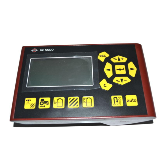
- Page 1 CONTROLLER HC5500 Service Manual – SW 4.XX 679060-702 – Version 7.02 GB – 11.2008 www.hardi-international.com...
-
Page 2: Table Of Contents
Service Manual HC5500 Table of contents: INTRODUCTION..............................4 SPECIFICATIONS ............................... 5 HARDI HC5500 C :............................5 ONTROLLER HC5500, S ................5 PRAY BOX AND OBCOM POWER SUPPLY AND PROTECTION FUNCTIONS AND FUNCTIONALITY ......................... 6 HC5500:........................6 ONNECTORS AT THE BACK OF THE :.............................. - Page 3 SOFTWARE UPLOAD JOBCOM........................49 HANDLING THE CONFIGURATION FILE......................55 Save the configuration file to the PC: ........................55 Send the configuration file to the HC5500: ....................... 56 DUMP OF DATA FROM HC5500 CONTROLLER.................... 57 Configuration of HC5500 to dump data ........................57 DUMP DATA FROM HC5500..........................
-
Page 4: Introduction
Commander and IntelliTrack on Navigator. It assumes the reader has knowledge of the more basic HC2500. The menu systems, calibration and operations of the HC5500 are built up from the HC2500. The sensors used are also similar or the same. -
Page 5: Specifications
Area 12. Volume used 13. Area covered 14. Tank volume 15. Speed 16. Volume rate HC5500, Spray box and JobCom power supply and protection Power supply: Operating range: 9-16V DC Controlled processor shut down: < 9 VDC Protected against over voltage: 28 VDC The electronics are protected against reverse polarisation of the power input. -
Page 6: Functions And Functionality
This is used for the liquid control box Spray I or Spray II box. D: AUX: This is used if the tractor speed sensor or the foot pedal is connected to the HC5500. Harness P/N 28027600 is necessary. Page 6 of 87... -
Page 7: Sprayer Connection
26003900 L=2m 26028300 L = 0,5m 5. JobCom or Breakout PCB 6. Cable P/N 26004900 7. 13 sec PCB P/N 26004800 NAVIGATOR: 1. HC5500 2. Spray II 3. Hydraulic Box 4. Cable P/N: 26004200 L = 17,5m 28028700 L=14m 28027500 L=11,5m... -
Page 8: Hydraulic Cables
Hydraulic cables Cables details can be found in the cables configuration chapter. Commander with JobCom: 1. HC5500 2. Spray II Box 3. Hydraulic Box 4. Cable P/N: 72236600, L=5m 72236400, L=8m 5. JobCom with DAH Interface 6. Cable P/N 26016900 7. -
Page 9: Amp Connectors
AMP connectors The AMP connectors have each of the legs numbered so they are easy to identify. The table shows how the wires are mounted in the plug and what function the wires have. AMP plug Pin & Wire connection AMP Super Seal Function Colour... -
Page 10: Optional Extras For The Hc5500
Optional extras for the HC5500 Printer A printer can be fitted for the HC5500, as shown on Picture 1. Printer Picture 1: Printer for the HC5500 The printer can print out several kinds of data from the HC5500. Picture 2 is an example of a printed register and Picture 3 a printed configuration. -
Page 11: Foot Pedal For Main On/Off Function
Picture 5: Wire harness for the HC5500 The setup of the foot pedal to the HC5500 is done in E8.5.1. The menu tree can be seen in section “Extended Menu 8”. There are two choices depending on the switch type. -
Page 12: Sensors
Type: Inductive Range: 0-8mm Signal: 0-200Hz Operation indicator: Yellow light when active (0,8V) Power: Visual indicator: LED to indicate active status Hardi Pin assignment: Brown + Blue signal Black - Front angle sensor: Hardi P/N 26005700 Type: Potentiometer Range: 0-70°... -
Page 13: Speed Sensor For Tractor: Wheel, Gearbox Or Radar
The signal from the tractors can however change a lot from brand to brand; consult your manual or tractor dealer for more information. The setup of the speed sensors in the HC5500 is done in the menu 3.1. Further instructions about the connection and calibration can be found in the instruction book. -
Page 14: Fan Speed On Twin
The version of the PCB used depends of what type of sprayer the sensor in mounted on. For the wire connections to the PCB, see section “PCB’s” on pages 70. When the pressure sensor is mounted on the sprayer, the HC5500 is setup to the sensor. In menu “5” on pages 21, the setup is shown. -
Page 15: Tankgauge
TankGauge The TankGauge (digital contents sensor) is a sensor that can measure how much liquid is in the tank. It has no automatic function. It can give a warning when the tank is about to run dry. Connecting TankGauge Wire between JobCom and 26007300 AMP Super Seal Wire Wire (old version) - Page 16 • When the sprayer is stationary When the sprayer is moving, the HC5500 will calculate an average value of the read out from the TankGauge. The average value is necessary because of the movement of the liquid in the tank will when the sprayer is moving. If a not averaged value was shown, the readout would be useless for the driver.
-
Page 17: End Nozzle Kit
The End nozzle kit is connected to the “PCB for section valves”, seen on page 71. For accurate boom width whilst using the end nozzles, Menu 3.3.4 needs to be set up. For more information, see in the instruction book for the HC5500. Picture 8 End Nozzle kit... -
Page 18: Extended Menu For Sw 4.00
Extended Menu 1 Language: Here the is language choice. There are standard languages and place for two local languages that can be uploaded to the HC5500 by a service person. Note: For Russian, the HC5500 hardware version with Cyrillic text is used. -
Page 19: Extended Menu 3 Sprayer Type
Extended Menu 3 Sprayer type E3.1 Field sprayer E3.1.1 Liquid system [Equalization, Not equalization, Circulation] Default is Equalization. Equalization = System with liquid return to tank from section valves; e.g. EVC. Not equalization = System without returns to tank; e.g. EFC on CM05. Circulation = System where liquid constantly circulates in the boom lines. -
Page 20: Extended Menu 4 Data Exchange
Data exchange E4.1.2 Baud rate [19200, 9600, 4800, 2400, 1200] Default is 9600. Use 9600 for HARDI 12 volt printer. E4.1.3 Protocol select [HARDI VRA proto.] Only one protocol available at the moment. COM 2 E4.2 setup E4.2.1 Equipment type... -
Page 21: Extended Menu 5 Optional Sensors
For Hardi TankGauge, choose Hardi. PCB or JobCom. E5.3.2 [0.000 to 999.999 PPU ] Connect to Breakout PCB or JobCom. See “TankGauge” section. Hardi has the TankGauge 0-250mbar pressure transducer fitted to sump. E5.X Sensor x Unit Default Only with Breakout... -
Page 22: Extended Menu 6 Service Interval
Extended Menu 6 Service interval E6.1 A hours 10 hours. E6.2 B hours 50 hours. Service interval E6.3 C hours 250 hours. PIN = 04711 E6.4 D hours Hours are not defined. E6.5 Nozzle 50 hours. Extended Menu 7 Factory settings E7.1 Total register E7.1.1 Register 0. - Page 23 Value set if a TankGauge is not fitted. Maximum fill: CM 3200=3500 CM 4400=4900 CM 6600=7000 NAV 3000=3300 NAV 4000=4400 E8.2.2 (Future use) E8.2.3 Data points [0000] Calibration values for HARDI TankGauge. Can be edited by use of Navigation and Enter keys. Page 23 of 87...
- Page 24 E8 Settings E8.3 (Future use) E8.4 Track E8.4.1 Enable [No, Yes] To enable Safe- or IntelliTrack function. E8.4.2 Sensor E8.4.2.1 Front sensor test Approx. 2.50 V when straight. Alarm given if < 0.2 Volt or > 4.8 Volt. E8.4.2.2 Rear sensor E8.4.2.2.
- Page 25 E8.4.6 Boom [0, 1, 2] sensors Default: 1. This is the number of boom fold sensors present. For CM: Choose 1 or 2 For NAV: Choose 0 E8.4.7 Error print [Yes] Prints last 3 hazardous situations and shows Alteration log changes. E8.4.8 Minimum [6.0 m] radius...
-
Page 26: Extended Menu 9 Jobcom
Extended Menu 9 JobCom E9.1 Enable [Yes, No] Must be enabled for use with Track or AutoSectionControl. E9.2 Communication [ID x; ACK: x NACK: x; Timeout x] ACK=acknowledged message, NACK= not acknowledged. ID= identification where "0" is JobCom, Timeout=No answer from JobCom. Date and time for error, ID of hardware with fault, M = E9.3 ComLog E9.3.1... - Page 27 E9.4.3 Analogue E9.4.3.1 Slant Volt E9.4.3.2 Boom height Volt Tilt L Volt E9.4.3.3 E9.4.3.4 Tilt R Volt E9.4.3.5 Foam blob dist Volt E9.4.3.6 Twin angle Volt E9.4.3.7 Twin fan speed Volt E9.4.3.8 Distance L Volt E9.4.3.9 Distance R Volt E9.4.3.10 Distance centre Volt E9.4.3.11 Extra 3 Volt...
- Page 28 Description 1 EVC compared to EFC The difference between the EVC and the EFC section valve is that the EFC section valve has no pressure equalisation. The equalisation is adjusted by the pressure regulation valve and is controlled by the computer. Picture 9 shows the EVC section valve, the circled being the equalisation valve.
-
Page 29: Track Setting In Extended Menu
Track setting in Extended Menu: The configuration of the sprayer is saved in the controller; these setting should only be set again after a master reset of the controller. Menu E 8.4.1 Enable Tracking can be either enabled/disabled in this Menu. If tracking is set to disabled, it will trail as a normal trailer. -
Page 30: Intellitrack Rear Sensor Calibration
IntelliTrack rear sensor calibration: At the factory of the angle of the drawbar is measured and there should be a label with the angel inside the JobCom lid of the sprayer. If you find the label with the angel it is not necessary to do the following measurement with the protractor, you can just put in the angle. - Page 31 Use the protractor, (72547300), to measure the maximum right angle Key in values in E.8.4.2.2.2.3 as shown. S: Value from rear sensor. C: This is the actual physically measured value with the protractor. Use the arrow keys to chance the value, finish with ENTER, and continue with the calibration.
-
Page 32: Menu: E 8.4.3 Chassis
NAV 07 M 4400 L 6000 L CM05 L If the HC5500 is not set up to the correct chassis, the system will not be accurate. Menu: E 8.4.4 Sprayer drawbar SafeTrack on COMMANDER Sprayer drawbar length is measured from... -
Page 33: Menu E 8.4.5 Manual Angling
The Safety factor will give an alarm and then straighten up the sprayer. The alarm can be accepted by pressing “Enter” on the HC5500 and it will operate normally again once the track is set to “Manual” and back to “Auto” on the Hydraulic control box. - Page 34 There are no adjustments for the system, it can only be activated or disabled. In section “Extended Menu 8” on page 23, it shows where the LookAhead system is activated or disabled in the HC5500. What is the LookAhead? The LookAhead is a system using the following components: •...
- Page 35 New tractors are often driven with clutch free gearboxes, e.g. Vario – Dynashift – CVX. These new gearboxes corrupt the Hardi-Matic system in the liquid system of the sprayer because they can change the ground speed without changing the rpm on the engine, PTO hence or liquid pump on the sprayer.
- Page 36 LookAhead needs to be calibrated to the capacity of the nozzles. Boom size and number of sections also have an influence so no standard calibration value that can be put into the HC5500. In some cases, LookAhead may have limited effect. For example: 1.
- Page 37 To prevent too manually setup of all parameters in the HC5500 after a software update or master reset is it possible to save the configuration to a computer and transfer it again to the controller after the update or reset.
- Page 38 Run Hardi HC Upgrade, double click on HardiExeUploadWin.exe and you will get a window like this: How to use the Hardi upgrade program is described in section “Software upload HC5500” and “Software upload JobCom”. A: Information about the current version of Hardi HC Upgrade.
- Page 39 The “Info” button shows the version information of the Hardi PC Uploader and software in the connected controllers. Page 39 of 87...
- Page 40 Communication cable The connection from the PC to the controller is made with HARDI cable P/N 72271600. The cable has a short circuit in one of the connector, normally where the label is. For software update this means HC5500 Loop in communication cable.
- Page 41 USB to RS232. The systems requirement to use a converter is: A computer with Windows XP or later. USB to RS232 serial converter, Hardi P/N 26025900. Serial NULL-modem cable, or Hardi “Communication cable” P/N 72271600. Install the USB to RS232 serial converter...
- Page 42 Push the “Finish” button. After a restart of the computer the adaptor is ready to use. Verify comport number. Before you can start upgrading your Hardi controller, you need to find the number of the USB-serial Converter. Click on the Windows “start” button and select “Control panel”.
- Page 43 Double-click on the “System” icon. Click on the “Hardware” tab. Click on the “Device manager” button Find and expand the “Ports” icon by clicking on the ‘+’ left to the icon. Now you will see a screen not so different from the picture above.
- Page 44 Software upload HC5500 The HC5500 software version is shown every time the controller is switched on. The communication cable without the “Hardware halt” is plugged into the PC. This is done before the computer is powered up. The communication cable with the “Hardware Halt”...
- Page 45 - Click “OK” to upgrade HC5500. - If HC5500 needs to upgrade boot software it will erase the old one, and the “Hardi HC Upgrade” will upload a new version. - Afterwards “Hardi HC Upgrade” will erase the current application on HC5500 and upload the new one.
Need help?
Do you have a question about the HC5500 and is the answer not in the manual?
Questions and answers