Hardi HC5500 Instruction Book
Hide thumbs
Also See for HC5500:
- Instruction book (80 pages) ,
- Service manual (45 pages) ,
- Installation manual (8 pages)

Subscribe to Our Youtube Channel
Related Manuals for Hardi HC5500


Summary of Contents for Hardi HC5500
- Page 1 The Sprayer Operator’s Manual CONTROLLER HC5500 Instruction book - sw 4.00 67021003 - Version 2.01 US - 11.2021...
- Page 3 67021003 - Version 2.01 US - 11.2021 HARDI® reserves the right to make changes in design, material, or specification without notice thereof. HARDI® and other product names are registered trademarks of HARDI® Inc. in the U.S. and in other countries.
-
Page 5: Table Of Contents
Operator safety ..............................1 General info................................................1 Local Poison Information Center ..........................2 3 - Description General info..............................1 General info ............................................1 Glossary and pictorial symbols ....................................2 HARDI® LookAhead........................................2 SafeTrack.............................................3 System description............................4 Overall description........................................4 Keys ................................5 General Key description ......................................5 General keystrokes, Example: Tank contents...............................6 Keystroke menu tree........................................8... - Page 6 Menu 2.2.2 Foam Marker (optional)..................................2 Menu 2.2.3 Dual line (not used in North America) ..........................2 Menu 2.3 VRA/Remote control ........................2 Variable Rate Application (VRA) / Remote/ HARDI® AutoSectionControl ................2 Menu 2.4 Set clock............................3 How to set clock..........................................3 Menu 2.5 Alarms............................4 How to set up alarms.........................................4...
- Page 7 Table of Contents 8 - Menu 4 Toolbox Menu 4.1 Measure ............................1 Trip meter ............................................1 Menu 4.2 Service intervals ...........................1 Menu and intervals........................................1 Service interval reset........................................1 Menu 4.3 Stop watch ............................2 Use as timer............................................2 Menu 4.4 Alarm clock ...........................2 How to use alarm .........................................2 Menu 4.5 Test ...............................2 How to test ............................................2 Menu 4.6 Speed simulation..........................2...
- Page 8 Table of Contents TOC. 4...
-
Page 9: Welcome
Some of the features on your HARDI® sprayer were suggested by growers. There is no substitute for “on farm” experience and we invite your comments and suggestions. If any portion of this instruction book remains unclear after reading it, contact your HARDI®... - Page 10 1 - Welcome...
-
Page 11: Safety Notes
Keep children away from the equipment. If any portion of this instruction book remains unclear after reading it, contact your HARDI® dealer for further explanation before using the equipment. Turn electrical power off before connecting and disconnecting the display and transducers, servicing or using a battery charger. -
Page 12: Local Poison Information Center
2 - Safety notes Local poison information center If you live anywhere in the United States, the following toll free number will connect you to your Local Poison Information Center. PHONE NO. 1 - 800 - 222 - 1222 If you live outside the United States, find the number for the poison control center in your phone book and write it in the space below: PHONE NO._______ - _______ - __________ Keep a list, in the space provided below, of all the chemicals that you have in use. -
Page 13: Description
3 - Description General info General info The HARDI® Controller 5500 is for use in agricultural and horticultural production. The Controller permits automatic con- trol of application rate. Main components are: * Controller * Spray Box * Junction box (on sprayer) -
Page 14: Glossary And Pictorial Symbols
Glossary and pictorial symbols Controller HARDI® Controller 5500 with display. Spray Box HARDI® Control Box with all basic control functions. Junction box Box on the sprayer for Controller and Control Box. Jobcom Box on the sprayer with SafeTrack computer and/or AutoSectionControl. -
Page 15: Safetrack
3 - Description SafeTrack SafeTrack is a steering mechanism for the HARDI® COMMANDER sprayer. When using a track system, sprayer stability is a common concern. Many factors influence the sprayer, and conditions where the sprayer might tip over have to be dealt with. -
Page 16: System Description
3 - Description System description Overall description 1. Controller 2. Spray Box 3. To 12 Volt power supply 4. Multi wire plug and cable 5. Junction box (on sprayer) 5A. Jobcom (optional) 6. Flow transducer 7. Speed transducer 8. Printer (optional) 9. -
Page 17: Keys
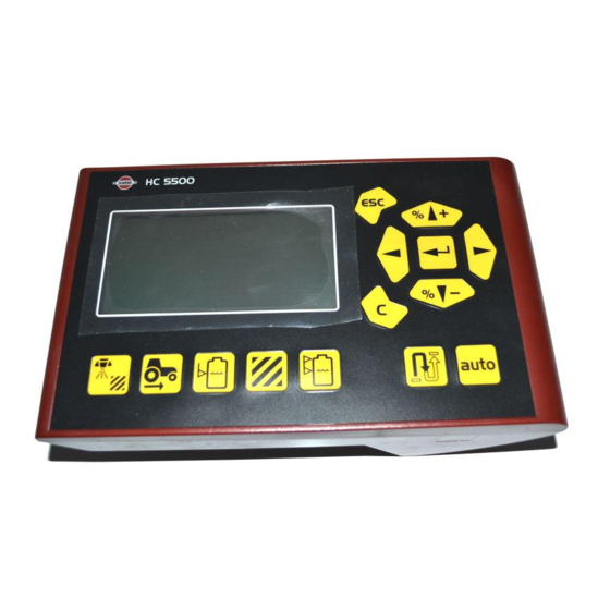
3 - Description Keys General key description The HC 5500 controller buttons are placed in three groups; naviga- tion keys, shortcut keys, distance and auto key. The shortcut keys can be used for the following: ¥: Short press: Displays volume sprayed for the active register. Long press: Enter Register select (menu 1.3.1 Register select). -
Page 18: General Keystrokes, Example: Tank Contents
3 - Description The navigation keys are used initially for set up in the menu system, and working screen. To navigate the menus, press # to start the process. While in the menu system, buttons can be used for the following: Pressing ¿... - Page 19 3 - Description Press # to enter the menu system [1 MAIN MENU]. The 2nd line will show the menu number. The 3rd line will read the present menu. The 4th line will show a choice. Note the menu number [1] is blinking. Press # to enter menu [1.1 Daily settings].
-
Page 20: Keystroke Menu Tree
3 - Description Keystroke menu tree The first steps to choose a menu are shown below. Press # to proceed into the menu. See the relevant section in the book. Press ~ and hold to exit the menu system. 5 Logbook 5.2 Data dump 5.1 Print 4 Toolbox... -
Page 21: Overview Of Buttons And Switches
3 - Description Overview of buttons and switches HC 5500 Display 1. Display 2. Navigation keys* 3. Shortcut keys* *pictorial symbols match icons used throughout manual. Spraybox II 1. Power switch 2. Manual pressure regulation 3. Main ON/OFF 4. End nozzle (Left/OFF/Right)* 5. - Page 22 3 - Description 3.10...
-
Page 23: System Setup
The supplied power connectors follow the standard of most newer tractors. If using a tractor with another power connector, it is neces- sary to disassemble connector and fit it to the existing connector. Use the HARDI® Electric distribution box (Ref. no. 817925) to ensure a good connection. LIGHTER CONNECTOR... -
Page 24: Printer
Note the following if the Foot pedal remote is to be fitted. Remote ON/OFF switch has to be activated from the extended menu at installation. The HARDI® Service center does this. The speed/switch harness (A) is connected to the Controller/Terminal. Connect the plug from the Foot pedal ON/OFF to the correct connector on harness (A). -
Page 25: Initial System Start-Up
4 - System setup Initial system start-up When connecting the 39 pin plug from the sprayer, note the one- way brackets inside the connector and connector plug. There are two different brackets to differentiate between the connector plug for the liquid (1) and hydraulic (2) boxes. Hook the top of connecting plug first, then make sure lock tab (A) clicks in place to secure the plug in the socket. -
Page 26: Daily Settings
4th line. This data should reflect the sprayer it is mounted to - if not, please contact your local HARDI® dealer to correct this. 3. If the sprayer is equipped with LookAhead and this is enabled in the HC 5500, it will prompt user for a nozzle choice - see section “LookAhead nozzle choice”. -
Page 27: Control Units
4 - System setup 3. If a selected nozzle holds no LookAhead calibration in the HC 5500 memory, then it should be calibrated - see section “Menu 3.7 LookAhead” in the chapter “Menu 3 Calibration”. Custom nozzle flow rate is also defined in “Menu 3.7.X LookAhead calibration”. - Page 28 4 - System setup...
-
Page 29: Menu 1 Daily Settings
5 - Menu 1 Daily settings Menu 1.1 Volume rate How to change the volume rate The volume rate can be changed by: 1. Setting the desired rate in the Controller. 2. Manually raising or lowering the pressure via the Spray Box. 3. -
Page 30: Menu 1.2 Tank Contents
5 - Menu 1 Daily settings Menu 1.2 Tank contents To change the displayed Tank contents Shortcut @ Press @ and hold until menu [1.2 TANK CONTENTS] is shown. The maximum size of the tank is displayed Press @ again and the tank contents maximum value is shown. Press ¶... -
Page 31: Menu 1.3 Select Register
5 - Menu 1 Daily settings Menu 1.3 Select register Menu 1.3.1 Register readout and selection Register 1 to 98 can be used for individual areas. Register 99 is a tally of register trips 1 to 98. They are identified with a number and it is also possible to name them. - Page 32 5 - Menu 1 Daily settings...
-
Page 33: Menu 2 Setup
6 - Menu 2 Setup Menu 2.1 Display readout General info The following menu explanations assume you have mastered the general keystrokes and you can “find your way” to the specific menu. If this is not so, please re-read section “Keys”. Menu 2.1.5 Work rate It is possible to freely choose which function is to be shown on the 3rd or 4th line of the display. -
Page 34: Menu 2.2 Auto Functions
Menu 2.2.2 Foam Marker (optional) The Controller can be set to operate the HARDI® Foam marker automatically through the main ON/OFF valve. When the main ON/OFF is ON, it will automatically start the Foam marker. Furthermore, the Foam marker can be set for up and back spraying or race-track (round and round) spraying. -
Page 35: Menu 2.4 Set Clock
6 - Menu 2 Setup Menu 2.4 Set clock How to set clock If the Controller prompts for date and time, [Set clock to enable register]: This must be done before the Controller is put into operation for the first time, otherwise no start and stop time will be recorded in the registers. -
Page 36: Menu 2.5 Alarms
6 - Menu 2 Setup Menu 2.5 Alarms How to set up alarms --Six different alarms can be set up. Choices are listed as follows. DISPLAY TEXT NOTES [2.5.1 Volume rate] Suggested setting is 10% [2.5.2 Tank contents] Measured in Gallons [2.5.3 Spray pressure] High/low pressure [2.5.4 Fan speed]... -
Page 37: Menu 2.6 Register Names
6 - Menu 2 Setup Menu 2.6 Register names How to name the registers If desired, the registers can be given names. Once set up, a name can be copied and edited. Press ¿ or ª to toggle between [Yes] or [No]. Press # if the name can not be copied or edited. - Page 38 6 - Menu 2 Setup...
-
Page 39: Menu 3 Calibration
7 - Menu 3 Calibration Menu 3.1 Speed calibration Menu 3.1.1 Sprayer The calibration process is the same for each sensor type. In the fol- lowing example a “speed sensor on sprayer“ is used. Shortcut * 1. Press * until menu [3.1.1 Sprayer] is shown. It is possible to connect the speed sensor at different locations. -
Page 40: Menu 3.1.1.1 Constant
7 - Menu 3 Calibration Menu 3.1.1.1 Constant The theoretical speed constant, pulses per unit (PPU), is the distance in feet on the circumference of the wheel between holes (or protru- sions / magnets) that the speed sensor records. Menu 3.1.1.2 Practical Practical calibration of speed is done by driving a measured distance and correcting the display so that the actual and the calculated dis- tances are the same. -
Page 41: Menu 3.2 Flow Calibration
7 - Menu 3 Calibration Menu 3.2 Flow calibration Which method to use The flow transducer can be calibrated theoretically or with two prac- tical methods. The practical methods are preferred. Calibration is done with clean water. The Flow Tank method is time consuming, but is more accurate than the Flow Nozzle method. -
Page 42: Menu 3.2.3 Tank Method
2. Go to menu [3.2.2 Nozzle method]. The display will then show the individual nozzle output per minute. 3. Using a HARDI® calibration jug, check the actual nozzle output per minute. It is recommended that an average of several nozzles be taken. -
Page 43: Menu 3.2.4 Circulation
The following is only relevant for sprayers equipped with circulation liquid system with 2 flowmeters. The circulation type liquid system has to be set up from the Extended menu at installation. The HARDI® Service center does this. See menu [3.2 Flow calibration] for calibration of “Flow 1”. Flow con- stant from “Flow 1”... - Page 44 7 - Menu 3 Calibration Method: 1. Ensure all boom sections and end nozzles are closed. 2. Go to menu [3.2.4.2 Calibrate circulation]. 3. Press #. The automatic calibration is initiated and line 4 will show “Calculating PPU”. 4. When finished, the menu returns to [3.2.4.1 Flow constant] to show the new PPU.
-
Page 45: Menu 3.3 Boom
7 - Menu 3 Calibration Menu 3.3 Boom Menu 3.3.1 Width Use the navigation keys to enter boom width. Press # to confirm. Menu 3.3.2 Number of sections Use the navigation keys to set number of boom sections. Press # to confirm. Menu 3.3.3 Nozzles/section Use navigation keys to set correct number of nozzles per section. -
Page 46: Menu 3.4 Regulation Constant
7 - Menu 3 Calibration Menu 3.4 Regulation constant Regulation constant The sensitivity of the pressure regulation valve can be adjusted. Increasing the regulation constant will give a faster response on the pressure regulation valve. If the constant is too high, the valve will become unstable. There will also be excessive wear on the valve. -
Page 47: Menu 3.5 Tank Gauge
Menu 3.5 Tank gauge General info This menu item is only present if the HARDI® Tank Gauge is fitted. For increased accuracy, it is recommended to do the flow calibration [3.2] before proceeding. Present accuracy is up to +/- 13 gallons. This is at the widest liquid surface area in the tank. The smaller the liquid surface area, the more accurate the readout. - Page 48 6. Correct the displayed volume with the ¿ or ª to the actual 3.5.2 volume sprayed out. 7. Press #. The new flow transducer PPU is calculated and the cali- bration of the HARDI® Tank Gauge is finished. TOTAL STEP Emptied XXXX gal ATTENTION! Do NOT overfill.
-
Page 49: Menu 3.6 Track
7 - Menu 3 Calibration Menu 3.6 Track General info There is no standard setting for the Track set up. The Track needs to be adjusted for different kinds of tractors, sprayers and spraying practices which can only be found under actual conditions. For example;... -
Page 50: Reversing The Sprayer
7 - Menu 3 Calibration Reversing the sprayer When reversing the sprayer, the controller will prompt “Reversing” in the display. When the track is in “auto” mode, the track will lock in the position it had when the tractor was stopped. This means that the same steering angle, if any, will be kept when the sprayer is reversed. -
Page 51: Menu 3.6.4 Damping
7 - Menu 3 Calibration Menu 3.6.4 Damping If the system is too aggressive, the damping constant must be increased. Failure to do so may damage the boom. Factory setting: 50% No damping (0%): High precision, but very unsteady. Fast reaction time, but more aggressive movement that potentially can damage the boom. -
Page 52: Emergency Track
7 - Menu 3 Calibration 5. Afterwards same procedure is repeated for opposite direction. ATTENTION! If value has not been reached by 40 %, the display will read “Fail!”. Accept this by pressing #. Then increase hydraulic oil flow from tractor and retry calibration again. The calibration automatically continues with gain calibration: 6. -
Page 53: Menu 3.7 Lookahead
7 - Menu 3 Calibration Menu 3.7 LookAhead Menu 3.7.X LookAhead calibration At start-up of the HC 5500, the user is prompted for a nozzle choice. If the selected nozzle holds no LookAhead calibration in the HC 5500 memory, it will need to be calibrated. Press ® to enable “auto”... - Page 54 ATTENTION! To calibrate, the speed must exceed the minimum speed set in the controller memory. If minimum driving speed is set too high, please contact your local HARDI® dealer. ATTENTION! If all section valves are turned off, then LookAhead is in standby. When turning single sections off, the last valve must be turned off by using the main on/off.
-
Page 55: Menu 4 Toolbox
8 - Menu 4 Toolbox Menu 4.1 Measure Trip meter This is a simple electronic trip meter. You can measure distance. If the implement width is entered in menu [4.1.3 Working width], area can also be measured in menu [4.1.2 Area]. Use | to clear the value. -
Page 56: Menu 4.3 Stop Watch
8 - Menu 4 Toolbox Menu 4.3 Stop watch Use as timer The clock can be used as a timer. Press # to start and stop. Use | to clear the value. Menu 4.4 Alarm clock How to use alarm The clock can be set to give an alarm when the time is reached. -
Page 57: Menu 4.7 Emergency Track
The system can be operated manually so it is possible to fold the boom and drive home. In the menu, the sensor voltages can be checked, which is useful for HARDI® service to solve the problem. F: Front potentiometer R: Rear potentiometer L: Lock sensor (no sensor reads 00.0 Volts) - Page 58 8 - Menu 4 Toolbox...
-
Page 59: Menu 5 Logbook
9 - Menu 5 Logbook Menu 5.1 Print What you can print This menu has to do with dumping and printing of data. The following can be printed via the 12 volt printer. [5.1.1 Register number] A specific register [5.1.2 All registers] Register 1 to 99. Only active ones will be printed. [5.1.3 Configuration] This records all the parameters of the Controller. -
Page 60: Menu 5.2 Data Dump
9 - Menu 5 Logbook Menu 5.2 Data dump How to dump data Enables data dump to an office printer. This could be done for example, by using the Hyper Terminal function in Microsoft Windows. Note the Hyper Terminal has to be activated and a communication cable (ref. no. 72271600) and 12 volt power supply to the Controller and Spray Box is needed. -
Page 61: 10 - Maintenance
10 - Maintenance Off-season storage Storage When the tractor and sprayer is parked, disconnect the power supply to the Spray Box. This will stop the system from using power. The Controller and Spray Box should be protected from moisture and should be removed if the tractor does not have a cabin. - Page 62 10 - Maintenance 10.2...
-
Page 63: 11 - Fault Finding
11 - Fault finding Emergency operation In an emergency situation The Spray Box can operate the control unit without the Controller. If you suspect the Controller is faulty, disconnect it from the Spray Box. Spraying can now be continued. If the fault persists, it is not the Controller. 11.1... -
Page 64: Operational Problems
11 - Fault finding Operational problems Operational faults FAULT PROBABLE CAUSE CONTROL/REMEDY Area is not being measured. Boom width or speed constant have not Enter the values in menu [3.3.1 Width] and [3.1 Speed calibra- been entered. tion]. Missing speed sensor. Check the sensor using menu [4.5.2 Speed], check the cable to the sensor for damage. -
Page 65: Mechanical Faults
11 - Fault finding Mechanical faults FAULT PROBABLE CAUSE CONTROL/REMEDY No speed readout. Incorrect speed sensor location chosen. Select the correct sensor on Sprayer, Tractor or Radar in menu [3.1.1 , 3.1.2 or 3.1.3]. Defective sensor cable. Check sensor using menu [4.5.2 Speed]. Error message that fuse is active. - Page 66 11 - Fault finding FAULT PROBABLE CAUSE CONTROL/REMEDY Unable to lock the SafeTrack. The back angle sensor possibly needs Place a 5/8” bolt (16-17 mm) in the calibrating hole on the adjustment. lock. Then adjust the rear angle sensor to 2.50 Volt. Alarm # 1 Lock is locked, but it should be open.
-
Page 67: 12 - Testing And Fine Tuning
12 - Testing and fine tuning Testing and fine tuning Fine tuning the flow constant - PPU Calibration of the flow transducer is carried out with clean water but small changes may occur when adding pesticides or fertilizer. This will effect the final readings. This is typically noted when the volume displayed on the display does not equal the actual known volume that was sprayed out. -
Page 68: Testing Speed Transducer
12 - Testing and fine tuning Testing speed transducer BROWN wire to positive of 12 volt battery. BLACK wire to negative. BLUE wire to multimeter. 1. Connect negative from multimeter to negative of battery. 2. Set multimeter to DC volt. 3. -
Page 69: 13 - Technical Specifications
13 - Technical specifications Specifications Specifications Supply voltage: 12 Volt DC Controlled shutdown “low battery”: 9 Volt DC Maximum supply: 16 Volt DC Maximum peak: 28 Volt DC Ambient temperature: 23°F to 158°F (– 5°C to + 70°C) Memory: Flash PROM non-volatile Digital transducers (option 2, 3 and 4): Square signal Frequency:... -
Page 70: Materials And Recycling
13 - Technical specifications Materials and recycling Packaging information Materials used for packaging are environmentally compatible. They can be safely deposited or they can be burnt in an incinerator. Disposal of electronics Cardboard: Can recycle up to 99% and therefore should be put into the waste collection system. Polyethylene: Can be recycled. -
Page 71: Charts
13 - Technical specifications Charts Chart for recording values Menu Function 1 - Values 2 - Values 3 - Values [3.2.1 Flow constant] Flow PPU [3.1.X.1 Speed constant] Speed PPU [3.4 Regulation constant] 13.3... - Page 72 13 - Technical specifications 13.4...
-
Page 73: 14 - Warranty
HARDI® dealer that such equipment is at the time of delivery to such purchaser, free from defects in material and workmanship and that such equipment will be warranted for a period of one year from the time of delivery to the end user, providing the machine is used and serviced in accordance with the recommendations in the Operator’s Manual and is... - Page 74 Department. Warranty claims filed without prior approval will be returned. 11. Claims under this policy MUST be filed with the HARDI® Service Department within thirty (30) days of when the work is performed or warranty shall be void unless prior arrangements are made.
- Page 76 HARDI North America Inc. ® 7301 Vine Street Court - Davenport, IA 52806 Ph: (563) 386-1730 Customer Service Email: service@hardi-us.com Email: info@hardi-us.com Website: www.hardi-us.com...
Need help?
Do you have a question about the HC5500 and is the answer not in the manual?
Questions and answers