
Subscribe to Our Youtube Channel
Related Manuals for Hardi HC 5500 SPRAY BOX III


Summary of Contents for Hardi HC 5500 SPRAY BOX III
- Page 1 CONTROLLER HC 5500 SPRAY BOX III Original Instruction book - SW 5.XX 67000400-301 - Version 3.01 GB - 12.2014 www.hardi-international.com...
- Page 2 Illustrations, technical information and data in this book are to the best of our belief correct at the time of printing. As it is HARDI INTERNATIONAL A/S policy permanently to improve our products, we reserve the right to make changes in design, features, accessories, specifications and maintenance instructions at any time and without notice.
-
Page 3: Table Of Contents
Table of Contents 1 - EC Declaration EC Declaration of conformity .........................7 2 - Safety notes Operator safety .............................9 Symbols ............................................9 General Info ..........................................9 3 - Description General info ............................11 Controller features ......................................11 Glossary and pictorial symbols ................................... 12 System description ..........................13 Main components ...................................... - Page 4 Table of Contents 6 - Menu 2, Setup Menu 2.1 Display Readout ........................33 General info ..........................................33 Example of readout ......................................33 Menu 2.1.1 Program : Actual ..................................33 Menu 2.1.2 Flow rate ......................................33 Menu 2.1.3 Optional sensor ..................................34 Menu 2.1.4 Time ........................................
- Page 5 Table of Contents Menu 3.5 Tank gauge ..........................53 General info ..........................................53 Menu 3.5.1 Adjustment ....................................53 Menu 3.5.2 Calibration ..................................... 54 Menu 3.5.3 Tank selection ..................................... 55 Menu 3.5.4 Offset empty ....................................55 8 - Menu 4, Toolbox Menu 4.1 Measure ..........................57 Tripmeter ..........................................
- Page 6 Table of Contents...
-
Page 7: Ec Declaration
1 - EC Declaration EC Declaration of conformity Manufacturer: Importer: HARDI INTERNATIONAL A/S Helgeshøj Allé 38 DK 2630 Taastrup DENMARK declare that the following product (information is to be filled out at the Pre-Delivery Inspection (PDI); Model no. Serial no. - Page 8 1 - EC Declaration...
-
Page 9: Safety Notes
Test the sprayer with clean water prior to filling it with chemicals. μ Press the keys with the underside of your finger. Avoid using your fingernails. μ If any portion of this instruction book remains unclear after reading it, contact your HARDI dealer for further explanation before using the equipment. - Page 10 2 - Safety notes...
-
Page 11: Description
3 - Description General info Controller features The HARDI Controller 5500 is for use in agricultural and horticultural production. The Controller permits automatic control of application rate. Main components are: • Controller HC 5500 • Spray Box III • Junction box for DF4 regulation •... -
Page 12: Glossary And Pictorial Symbols
Glossary and pictorial symbols Controller HARDI Controller 5500 with display and pushbuttons. Spray Box III HARDI Control Box in the tractor with all basic control functions for the sprayer. Junction box Box on the sprayer for Controller and Spray Box. Sensor Device that transforms variations to a signal;... -
Page 13: System Description
3 - Description System description Main components 13 14 1. Controller HC 5500 2. Spray Box III 3. To 12 volt power supply 4. Multi-wire plug and cable to sprayer 5. Printer * 6. Wire harness for tractor speed, area switch and footswitch ON/OFF * 7. -
Page 14: Dynamicfluid4 Pressure Regulation
3 - Description DynamicFluid4 pressure regulation Traditional fluid regulation starts, when the nozzles are opened. With DynamicFluid4 (DF4), the regulation is a continuous process, even if the nozzles are closed. Two ceramic (or plastic) discs regulate the pressure and ensures quick reaction and zero leakages. Sprayer speed, PTO speed and number of spray sections activated are parameters used, and the benefit is more precise application rates from the second the sprayer begins spraying. -
Page 15: Keys And Display
3 - Description Keys and Display General description of controller keys The controller keys are placed in three groups: 1. Navigation keys (to the right of display) 2. Shortcut keys (below display) 3. Distance key and auto key (bottom right corner) Navigation keys They are initially used for set up in the menu system and working screen. - Page 16 3 - Description Press • Decrease volume rate in steps or select another preset application rate. Press • Reset the active register (hold until countdown is finished). Press • Enter a menu. Short cut keys You can either press the keys shortly or a little longer to display different functions. The shortcut keys can be used for the following: Short press: Displays volume rate sprayed for the active register.
-
Page 17: General Description Of Display
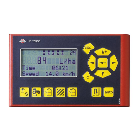
3 - Description General description of display There are four lines with symbols, numbers and text when looking at the working screen. The appearances of these items at the screen depend on the controller settings and spray functions. line : line : line : line :... -
Page 18: General Description Of Switches For Spray Box Iii
If a constant red light is shown, there is a malfunction in the Spray Box, and you should contact HARDI for technical assistance. 2. Pressure regulation - Adjusting the spray pressure up or down manually. When this switch is activated, the hand symbol appears in the top left corner of the controller display. -
Page 19: General Keystrokes, Example
3 - Description General keystrokes, example The following is a general description in keystrokes and display readout on the controller. The following example, of changing the tank contents value, is used to illustrate this. Try it! The same method is used in all the menus. μ... -
Page 20: Options Control On Spray Box Iii, Example
3 - Description Options control on Spray Box III, example Optional equipment : Dilution kit The control switch for optional equipment can be flicked left or right. See the section “General description of switches for Spray Box III” to locate the switch. When the switch for operating the dilution kit is flicked to the left, the display line 3 and 4 show this: DILUTION... -
Page 21: Menu Tree
3 - Description Menu tree The first steps for choosing a menu are shown below. Menus and submenus are described in the relevant sections in this instruction book. When on the start screen / working screen, press to proceed into the menu. Press and hold to exit the menu system. - Page 22 3 - Description...
-
Page 23: System Setup
(A), as shown on the picture. μ ATTENTION! An extension cable is available as an option, if the HC 5500 control unit is to be placed further away from the EFC control unit. Contact HARDI for further details. -
Page 24: Power Supply
Hydraulic control unit requires: Wire 4.0 mm², fuse 16 amp. ± WARNING! Do not connect to the starter motor or generator/alternator. The HARDI warranty is void, if this is done. μ ATTENTION! See the section “System start-up” for more about connecting the controller. -
Page 25: Speed Sensor For The Sprayer
4 - System setup Speed sensor for the sprayer The speed sensor is located at the inside of the sprayers right wheel. It measures the sprayer’s ground speed. It is an inductive type that requires a metallic protrusion to pass by it to trigger a signal. -
Page 26: Footswitch Remote
Note the following if the footswitch remote is to be fitted. • The remote has to be activated from the extended controller menu at installation - contact your HARDI service centre. • The speed/switch wire harness (A) is connected to the Controller. -
Page 27: Daily Settings
• number of spray sections programmed into the controller in the line of the display. BOOM: XX.X m SECTIONS: μ ATTENTION! These data should reflect the actual sprayer - if not, please contact your local HARDI dealer to correct this. - Page 28 4 - System setup...
-
Page 29: Menu 1, Daily Settings
5 - Menu 1, Daily Settings Menu 1.1 Volume rate How to change the volume rate The volume rate (litres/hectare) can be changed by doing one of the following four actions. 1. Set the desired rate in the Controller menu [1.1 VOLUME RATE]. This menu can be accessed by pressing for a few seconds. -
Page 30: How To Read The Preset Volume Rate
5 - Menu 1, Daily Settings How to read the preset volume rate Shortcut key on the controller. Press and hold, until menu [1.1 VOLUME RATE] is shown. ÷ NOTE! Default value: 200 litres/hectare. How to use manual dosage To dose your spraying manually, use the pressure switch on the Spray Box (yellow switch). The manual mode is indicated by symbol at the top of the display. -
Page 31: Menu 1.2 Tank Contents
5 - Menu 1, Daily Settings Menu 1.2 Tank contents How to change the tank contents Shortcut key Press and hold, until menu [1.2. TANK CONTENTS] is shown. The maximum size of the tank is displayed. TANK CONTENTS 0000 L Press again and the tank contents maximum value is shown. -
Page 32: Menu 1.3 Select Register
5 - Menu 1, Daily Settings Menu 1.3 Select register How to select a register and its data Register 1 to 98 can be used for individual spray areas. They are identified with a number and it is also possible to name them. 1.3.1 The active register is always visible in the right upper corner of the display (se arrow). -
Page 33: Menu 2, Setup
6 - Menu 2, Setup Menu 2.1 Display Readout General info When reading the following menu explanations, it is assumed that you have mastered the general keystrokes and you can “find your way” to the specific menu. If this is not so, please read the section “Keys” again. Example of readout It is possible to choose freely, which function is to be shown on the 3 or 4... -
Page 34: Menu 2.1.3 Optional Sensor
6 - Menu 2, Setup Menu 2.1.3 Optional sensor There are up to 3 sensor options. Submenus: 2.1.3 [2.1.3.1Pressure]. Spray pressure (bar). [2.1.3.2 Fan]. TWIN fan speed (rpm). DISPLAY READOUT [2.1.3.3 RPM sensor]. Pump speed (rpm). Optional sensor Menu 2.1.4 Time Actual time (hours and minutes). -
Page 35: Menu 2.1.8 Speed
6 - Menu 2, Setup Menu 2.1.8 Speed Driving speed (kilometres per hour). 2.1.8 DISPLAY READOUT Speed Menu 2.1.9 Volume : Area 2 readouts on the same line for volume (litres) and area (hectares). 2.1.9 DISPLAY READOUT Volume : Area Menu 2.1.10 Active boom size Active boom size including end nozzles (metres). -
Page 36: Menu 2.2 Auto Functions
Auto ON/OFF Menu 2.2.2 Foam marker (optional) The Controller can be set to operate the HARDI Foam marker automatically through the main ON/OFF valve. When the main ON/OFF is ON, it will automatically start the foam marker. Furthermore, the foam marker can be set for back and forth spraying or race track spraying (round and round). -
Page 37: Menu 2.3 Vra/Remote
The baud rate for the equipment should be set at one of the following values before transmitting data: • 19200 baud • 9600 baud (default for HC 5500) • 4800 baud • 2400 baud • 1200 baud μ ATTENTION! The COM port may have to be set up in the extended menu. Contact your HARDI service centre. -
Page 38: Menu 2.4 Set Clock
6 - Menu 2, Setup Menu 2.4 Set Clock How to set clock If the controller prompts for date and time, the clock must be set to enable a register. This must be done before the controller is put into operation for the first time, otherwise no start and stop time will be recorded in the registers. -
Page 39: Menu 2.5 Alarms
6 - Menu 2, Setup Menu 2.5 Alarms How to set up alarms 5 different alarms can be set up in the following menus 2.5.1 - 2.1.5. When outside the alarm parameters, the relevant alarm will flash in the display. The alarm beep can also be adjusted in audio level in menu [2.5.6 Audio level]. -
Page 40: Menu 2.5.4 Fan Speed
6 - Menu 2, Setup Menu 2.5.4 Fan speed TWIN blower speed limits in rpm. 2.5.4.1 Adjust the limit value with Press to save. HIGH LIMIT Press and hold to exit the menu system. 0000 rpm 2.5.4.2 LOW LIMIT 0000 rpm Menu 2.5.5 Speed Driving speed limits in km/h. -
Page 41: Menu 2.5.7 Sections Off
6 - Menu 2, Setup Menu 2.5.7 Sections off Enable or disable warning in the display, when the main ON/OFF is ON (green switch in the top right corner of the Spray Box), and one or more spray sections are OFF. 2.5.7 Enable Warning will appear in the display. -
Page 42: Menu 2.6 Register Names
6 - Menu 2, Setup Menu 2.6 Register Names How to name the registers If desired, the registers can be given names. Once set up, a name can be copied and edited. Press to toggle between [Yes] or [No]. Press if the name can not be copied or edited. -
Page 43: Menu 3, Calibration
7 - Menu 3, Calibration Menu 3.1 Speed calibration Menu 3.1.1 Sprayer The calibration process is the same for each sensor type. In the following example, a “speed sensor on sprayer” is used. 3.1.1 Shortcut button when on the working screen. SPEED 1. -
Page 44: Menu 3.1.1.1 Constant
7 - Menu 3, Calibration Menu 3.1.1.1 Constant The theoretical speed constant, pulses per unit (PPU), is calculated from this formula: 3.1.1.1 CONSTANT PPU = 06.000 PPU A = number of metal protrusions in the speed ring inside the wheel, which the speed sensor records during one full turn of the wheel. -
Page 45: Menu 3.2 Flow Calibration
7 - Menu 3, Calibration Menu 3.2 Flow calibration Which method to use The flow sensor can be calibrated theoretically or with two practical methods. The practical methods are preferred. Calibration is done with clean water. The Flow Tank method is time consuming, but is more accurate than the Flow Nozzle method. -
Page 46: Menu 3.2.2 Nozzle Method
2. Go to menu [3.2.2 Nozzle method]. The display will then show the individual nozzle output per minute. NOZZLE METHOD Close end nozzle 3. Using a HARDI calibration jug, check the actual nozzle output per minute. It is recommended that an average of several nozzles is taken. 3.2.2 4. -
Page 47: Menu 3.2.3 Tank Method
7 - Menu 3, Calibration Menu 3.2.3 Tank method During practical flow calibration the tank is partly emptied through the nozzles. Whilst emptying, the display calculates the quantity emptied on the basis of the actual calibration value (PPU). The quantity displayed is 3.2.3 compared with the quantity actually dosed. -
Page 48: Menu 3.3 Boom
7 - Menu 3, Calibration Menu 3.3 Boom Menu 3.3.1 Width Use the navigation keys to enter boom width. Press to confirm. 3.3.1 WIDTH 00.0 m Menu 3.3.2 Number of sections Use the navigation keys to set number of boom sections. Press to confirm. -
Page 49: Menu 3.4 Regulation Constant
• Select a value below and enter it in this menu. Use the arrow keys to select and change the digits in the display and press Enter to save. 3.4.1 Flow house Flow (l/min) FL-SENSOR RESTR. HARDI 13.5 mm HARDI 20 mm HARDI 36 mm ÷ NOTE! Default value: 156 l/min. -
Page 50: Menu 3.4.2 Simulated Speed Value
Furthermore, when the spraying speed drops below the lowest speed value, where a spray job can begin when starting at headland (this speed is set by the HARDI dealer), the speed will be simulated to 3.4.2 maintain normal spray pressure, until the normal spraying speed is maintained. -
Page 51: Menu 3.4.3 Nozzle Size Flow At 3 Bar
ATTENTION! If changing nozzles while a sensor is faulty, remember to type in the size of the new nozzle. Nozzle size is defined as flow at 3 bar as shown in the HARDI nozzle catalogue. You can also find flow values in the table below. -
Page 52: Menu 3.4.6 Regulation Parameter
7 - Menu 3, Calibration Menu 3.4.6 Regulation parameter Code for special machines or applications, consult your HARDI service centre if in doubt. 3.4.6 ÷ NOTE! Default value: 1. REGULATION RPM... -
Page 53: Menu 3.5 Tank Gauge
Menu 3.5 Tank gauge General info This menu item is only present, if the HARDI Tank Gauge is fitted. For increased accuracy, it is recommended to do the flow calibration before proceeding. See menu [3.2.3 Tank method]. The tank content is measured from the bottom of the main tank using a fluid pressure sensor. -
Page 54: Menu 3.5.2 Calibration
7 - Menu 3, Calibration Menu 3.5.2 Calibration Calibration of the HARDI Tank Gauge is necessary to take into account the height of hitch point on the tractor and tyre mounting. Avoiding this may result an inaccurate calculation of the tank contents. -
Page 55: Menu 3.5.3 Tank Selection
Menu 3.5.3 Tank selection In this menu you can choose from a series of sprayer models, where the tank gauge has been precalibrated at the HARDI factory. This calibration has been completed with the tractor and sprayer on level ground. - Page 56 7 - Menu 3, Calibration...
-
Page 57: Menu 4, Toolbox
8 - Menu 4, Toolbox Menu 4.1 Measure Tripmeter This is a simple electronic tripmeter. You can measure distance when driving. Use to reset the value. 4.1.1 If the sprayer width is entered in menu [4.1.3 Working width], the area can also be measured in menu [4.1.2 Area]. -
Page 58: Menu 4.2 Service Interval
Service intervals and a nozzle check are programmed into the controller. This makes it easier for the operator to remember the service intervals. If the intervals are to be changed, contact your HARDI service centre for more information. From the factory, the Controller is set up with three service reminders and one nozzle check reminder. -
Page 59: Menu 4.3 Stopwatch
8 - Menu 4, Toolbox Menu 4.3 Stopwatch Use as timer This clock can be used as a timer. Press to start and stop. Press to reset the time. STOP WATCH 00:00:00... -
Page 60: Menu 4.4 Alarm Clock
8 - Menu 4, Toolbox Menu 4.4 Alarm clock How to use the alarm clock The clock can be set to give an alarm, when the time is reached. Press the arrow keys to set the alarm time and confirm with Turn the alarm clock off by pressing ALARM CLOCK Alarm set... -
Page 61: Menu 4.5 Test
8 - Menu 4, Toolbox Menu 4.5 Test How to make equipment test All readouts for the sensors are in accumulated counts, i.e. one signal gives one count, except for optional (analog) sensors, which are read in milliamperes (mA). Go to menu [4.5 TEST]. Choose the item to be tested and open the menu. Activate sensor and see if the signal is detected. Menu 4.5.1 Flow calculation. - Page 62 8 - Menu 4, Toolbox Menu 4.5.4 Active switches Enter this menu to test the number of activated switches. 4.5.4 ACTIVE SWITCHES Activated Menu 4.5.5 Regulat. sensors Enter this menu to test the sensors for the DynamicFluid 4 (DF4) regulation. [4.5.5.1 Boom pressure].
-
Page 63: Menu 4.6 Speed Simulation
8 - Menu 4, Toolbox Menu 4.6 Speed simulation How to use speed simulation Speed may be simulated for several reasons as described in the sections below. When setting the simulated speed in this menu, the value will remain valid, until the Controller is restarted or the value is set to “00”. - Page 64 8 - Menu 4, Toolbox...
-
Page 65: Menu 5, Logbook
9 - Menu 5, Logbook Menu 5.1 Print What you can print The following can be printed via the 12 volt printer. Menu 5.1.1 Register number Enter this menu to print a specific register with spraying data. By using the arrow keys, the register number in the top right corner can be 5.1.1 adjusted. -
Page 66: Menu 5.2 Data Dump
• 2400 baud • 1200 baud If only the display unit is to be removed from the tractor, a 12 volt power supply cable (HARDI item no. 72244500) is needed. The following can be printed to an office printer: Menu 5.2.1 Raw data Enter this menu to dump the data at once without a column header. -
Page 67: 10 - Maintenance
10 - Maintenance Off-season maintenance Off-season storage When the tractor and sprayer is parked, disconnect the power supply to the Spray Box. This will stop the system from using power. The Controller and Spray Box should be protected from moisture. They should be removed, if the tractor does not have a cabin. - Page 68 10 - Maintenance...
-
Page 69: 11 - Fault Finding
11 - Fault finding Emergency Operation In an emergency situation The Spray Box III can operate the control unit without the Controller. If you suspect the Controller is faulty, disconnect it from the Spray Box. Spraying can now be continued. If the fault persists, it is not because of Controller errors. -
Page 70: Operational Problems
11 - Fault finding Operational Problems Operational faults FAULT PROBABLE CAUSE CONTROL/REMEDY Area is not being measured. Boom width or speed constant have not Enter the values in menu [3.3.1 Width] and [3.1 Speed calibration]. been entered. Missing speed sensor. Check the sensor using menu [4.5.2 Speed], check the cable to the sensor for damage. -
Page 71: Operation When A Sensor Fails
11 - Fault finding Operation when a sensor fails When one of the sensors for pump speed, flow or pressure fails, the system will work in a limp-home mode, with reduced although acceptable performance. One of the alarms between ID numbers 5 and 9 will be triggered in the controller display. See also the section “Alarm list”... -
Page 72: Fluid System Test
11 - Fault finding Fluid system test A way to troubleshoot the sprayer is to complete these steps to check the fluid system for defects. 1. Close the main ON/OFF valve. 2. Close the regulation valve by pushing up the yellow button on the Spray Box III to increase the pressure. A yellow diode lights up on the valve, when it is closed. -
Page 73: Alarm List
Motor fail Alarm SENSOR ALARM Short circuit of a sensor with 5 volt supply. Contact your HARDI sevice centre. 5V supply Alarm SENSOR ALARM Short circuit of a sensor with 12V supply. Contact your HARDI sevice centre. - Page 74 11 - Fault finding...
-
Page 75: Testing And Fine Tuning
12 - Testing and fine tuning Testing and fine tuning Fine tuning the flow constant - PPU Calibration of the flow sensor is carried out with clean water. However, small changes may occur when adding pesticides or fertilizer. This will effect the final readings. This is typically noted, when the volume shown on the display does not equal the actual known volume that was sprayed out. -
Page 76: Testing Flow Sensor
12 - Testing and fine tuning Testing flow sensor • BROWN wire to positive of 12 volt battery. • BLACK wire to negative. • BLUE wire to multimeter positive. 1. Check the rotor turns freely. 2. Each vane in the rotor has a magnet in it with the pole facing out. Check that the 4 magnets are present. -
Page 77: 13 - Technical Specifications
13 - Technical specifications Specifications Electrical properties Supply voltage: 12 Volt DC Controlled shutdown “low battery”: 9 Volt DC Maximum supply: 16 Volt DC Maximum peak: 28 Volt DC Ambient temperature: – 5°C to + 70°C Memory: Flash PROM non-volatile Digital sensors (option 2, 3 and 4): Square signal Frequency:... -
Page 78: Materials And Recycling
13 - Technical specifications Materials and Recycling Disposal of electronics Cardboard: Recyclable up to 99% and therefore should be disposed into the waste collection system. Polyethylene: Recyclable. When the operating unit has completed its working life, it must be thoroughly cleaned. The synthetic fittings can be incinerated. -
Page 79: Notes
13 - Technical specifications Notes Table for recording values Menu Function Value 1 Value 2 Value 3 [3.2.1 Flow constant] Flow PPU [3.1.X.1 Speed constant] Speed PPU [3.4 Regulation constant]... - Page 80 13 - Technical specifications...
- Page 81 Index Index Service interval reset, 58 Service intervals, 58 Alarm clock, 60 Spare parts, 83 Alarm list, 73 Specific gravity, 53 Alarms, 39 Specifications, 77 Auto functions, 36 Speed calibration, 43 Speed sensor, 61, 76 Speed simulation, 63 Boom calibration, 48 Stopwatch, 59 Storage, 67 Calibrated tank gauge, 55...
- Page 82 Index...
- Page 83 Spare parts To see updated spare part information, the website www.agroparts.com can be visited. Here all parts information can be accessed, when free registration has been made.
- Page 84 HARDI INTERNATIONAL A/S Helgeshøj Allé 38 - DK 2630 Taastrup - DENMARK...
Need help?
Do you have a question about the HC 5500 SPRAY BOX III and is the answer not in the manual?
Questions and answers