ZIEHL-ABEGG ECblue Basic Assembly Instructions Manual
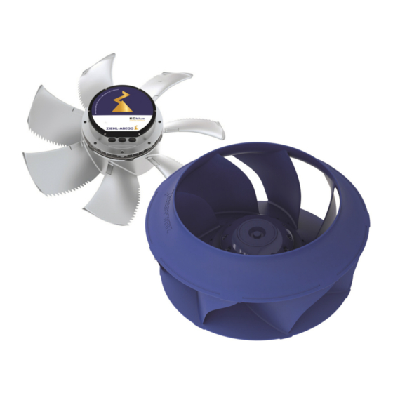
Ec- fans with highest efficiency for livestock houses
Hide thumbs
Also See for ECblue Basic:
- Assembly instructions manual (59 pages) ,
- Operating instructions manual (10 pages) ,
- Quick start manual (32 pages)

Related Manuals for ZIEHL-ABEGG ECblue Basic


Summary of Contents for ZIEHL-ABEGG ECblue Basic
- Page 1 ECblue Basic Motor sizes: D (116), G (152) EC- fans with highest efciency for livestock houses Assembly instructions Keep for reference! L-BAL-F053-GB 1601 Index 008 Part.-No. 00299816-D-GB...
-
Page 2: Table Of Contents
Assembly instructions ECblue Basic Content General notes .......... - Page 3 Assembly instructions ECblue Basic 4.7.1 Mounting with plastic brackets ..... 4.7.2 Mounting with stainless steel brackets ....
- Page 4 Assembly instructions ECblue Basic Enclosure ..........
-
Page 5: General Notes
We do not accept any liability for possible errors or omissions in the information con- tained in data, illustrations or drawings provided. ZIEHL-ABEGG SE is not liable for damage due to misuse, incorrect use, improper use or as a consequence of unauthorized repairs or modifications. -
Page 6: Copyright
These assembly instructions contain copyright protected information. The assembly instructions may be neither completely nor partially photocopied, reproduced, translated or put on data medium without previous explicit consent from ZIEHL-ABEGG SE. Infringements are liable for damages. All rights reserved, including those that arise through patent issue or registration on a utility model. -
Page 7: Safety Instructions
ECblue housing. housing. Note: The modules (AM-MODBUS-W and AM-PREMIUM-W) are stricly limited for the integration and usage with host devices manufactured by ZIEHL-ABEGG SE. 2 Safety instructions This chapter contains instructions to prevent personal injury and property damage. These instructions do not lay claim to completeness. In case of questions and problems, please consult our company technicians. -
Page 8: Explanations Of Symbols
Assembly instructions ECblue Basic Safety instructions • Fans are not designed for walking on even with an additive diffusor attachment (retrofit kit)! Do not climb onto fans without suitable aids. • Unauthorised constructional modifications to the fan. • Operation of the fan as a safety component or for the performance of safety-relevant functions in the sense of EN ISO 13849-1. -
Page 9: Requirements Placed On The Personnel / Due Diligence
Assembly instructions ECblue Basic Safety instructions 2.5 Requirements placed on the personnel / due diligence Persons entrusted with the planning, installation, commissioning and maintenance and servicing in connection with the frequency inverter must have the corresponding qual- ifications and skills for these jobs. -
Page 10: Modifications / Interventions In The Device
ZIEHL-ABEGG.These parts were specifically designed for the device. There is no guarantee that parts from non-original sources are designed and manufactured in correspondence with load and safety requirements. Parts and optional equipment not supplied by ZIEHL-ABEGG are not approved by ZIEHL-ABEGG for use. 2.8 Operator’s obligation of diligence •... -
Page 11: Employment Of External Personnel
The fans may not be operated until they are installed in line with their intended use. The supplied and certified guard grille of ZIEHL-ABEGG SE fans is designed in accordance with DIN EN ISO 13857 Table 4 (from the age of 14 up). In the event of deviations, further structural protective measures must be taken for safe operation. -
Page 12: Note On The Erp Directive
Product overview 3.4 Note on the ErP directive ZIEHL-ABEGG SE wishes to point out that, based on the directive (EU) no. 327/2011 of the Commission of 30th of March 2011 for enforcing directive 2009/125/EC (hereinafter referred to as ErP directive), the operational area of certain fans within the EU is bound by certain prerequisites. -
Page 13: Disposal / Recycling
Assembly instructions ECblue Basic Mounting 3.6 Disposal / recycling Disposal must be carried out professionally and in an environmentally friendly way in accordance with the respective national legal stipulations. Separate the materials by type and in an environmentally friendly way. -
Page 14: Connection Lead & Terminal Box
Assembly instructions ECblue Basic Mounting • Before the first switch-on, remove any items that may be present (borings, screws and other foreign objects) from the intake area - risk of injury from any objects that may fly out! 4.2 Connection lead & terminal box... -
Page 15: Connecting The Conduit For Nec And Cec Approval
Compliance with the following specifications is mandatory for this: • Metric to inches threaded adapters, used to connect the conduits, can be ordered from ZIEHL-ABEGG in a package of : – for MK116: part number 00297623 – for MK152: part number 00297624 •... -
Page 16: Connection In Nfpa 79 Applications
4.5.2 Connection in NFPA 79 Applications In applications where the NFPA 79 (Electrical Standard for industrial machinery) applies the enclosed cable glands can be used. The cable glands can be ordered additionally in packages of from ZIEHL-ABEGG: • for MK116: part number 00295308 •... -
Page 17: Fan Designs A And D (Without Nozzles)
Assembly instructions ECblue Basic Mounting 4.6 Fan designs A and D (without nozzles) For attachment to fixed motor flange use screws with property class A2-70 (stainless steel) to EN ISO 4014 and provide with suitable screw locking. Permissible tightening torques M... -
Page 18: Installation In An Exhaust Air Stack, Design T
Assembly instructions ECblue Basic Mounting 4.7 Installation in an exhaust air stack, design T 4.7.1 Mounting with plastic brackets • Mark and bore position of the mounting brackets (2) in the chimney (3) by means of a stencil 4x90°. In the case of soft foam tubing, place a sufficiently dimensioned washer made of corrosion-resistant material under mounting brackets and the screwed con- nection from outside. -
Page 19: Mounting With Stainless Steel Brackets
Assembly instructions ECblue Basic Mounting 4.7.2 Mounting with stainless steel brackets Mounting the stainless steel brackets is done with a separately obtainable installation kit. Mark the mounting bracket (4) in accordance with fig. 1 in the chimney (3) using a 4 x 90° template, drill hole center distance “a”... -
Page 20: Zaplus Fans
Assembly instructions ECblue Basic Mounting Installation kit (Part.-No. 00370979 / 00372782) Pos. Description Piece Axial fan Chimney Mounting bracket Support bracket M8x70 screws EN ISO 4014 M8 nuts EN ISO 10511 self-locking 8.4 washer EN ISO 7089 Protective cap Screw M8x30 EN ISO 4017 / screw M8x25 EN ISO4017 M8 nuts EN ISO 10 511 self-locking 8.4 washer EN ISO 7089... -
Page 21: Electrical Installation
Assembly instructions ECblue Basic Electrical installation 5 Electrical installation 5.1 Safety precautions Danger due to electric current • Work on electric components may only be carried out by trained electricians or by persons instructed in electricity under the supervision of an electrician in accordance with electrical engineering regulations. -
Page 22: Version With Connection Cables
Assembly instructions ECblue Basic Electrical installation 5.2 Version with connection cables In versions with connecting lead the connection is made to the colour coded wires. 1 ~ ECblue, for line and relay: hose cable 5 x 1.5 mm (LiF9Y11Y-JB) brown... -
Page 23: Version Without Connection Cables
Assembly instructions ECblue Basic Electrical installation 5.3 Version without connection cables 1 Cover of controller housing 2 Cable glands + seal insert for two cables (applicable only if necessary) - motor size “D”: 3 x M16 + 1 x seal insert with two holes 5 mm - motor size “G”: 3 x M20 + 1 x seal insert with two holes 6 mm... - Page 24 Assembly instructions ECblue Basic Electrical installation Attention! • Temperatures up to 80 °C can be present on the controller housing. • To connect, always use heat resistant wires or, as an alternative, silicon tubes. • Only use lines which can guarantee a permanent seal around the cable glands (pressure-resistant, dimensionally-stable, round-centred jacket;...
-
Page 25: Emc-Compatible Installation
Assembly instructions ECblue Basic Electrical installation Max. cross section of terminals Mains connection: PE, L1, N or PE, L1, L2, L3 max. 2.5 mm and/or AWG12 Connection control: +24 V, +10 V, GND, D1, E1, K1 max. 1.5 mm and/or AWG16 Add-on modules: 1.5 mm... -
Page 26: Required Quality Attributes For The Mains Voltage
Assembly instructions ECblue Basic Electrical installation Attention! To activate the on current limitation, you must wait at least 90 seconds after switching off the line voltage before switching back on! For 3 ~ fan types Mains connection to: PE, L1, L2 and L3. -
Page 27: Operating In It-System
Assembly instructions ECblue Basic Electrical installation 5.5.5 Operating in IT-System Danger due to electric current • In the IT-System the neutral point of voltage supply is not grounded; in the case of a short-circuit between a phase (e.g. “L1”) and protective earth “PE” becomes the protective earth potential = phase. -
Page 28: Motor Protection
Assembly instructions ECblue Basic Electrical installation Danger due to electric current Exception: All-current-sensitive fault current circuit breaker on the 3 ~ 230 V line When connecting the device between two outer conductors, “all-current-sensitive” fault current circuit breakers must be used ( EN 50 178, Art. - Page 29 10V GND 10 k f = 1...10 kHz 15...28 V Connection to ZIEHL-ABEGG ventilation computer with PWM output CTE/AH(X)-L (A4) The motor always starts with at least 6 % of the rated speed and stops below 4.5 % of the rated speed (providing that the “Min. Speed” setting is “0” rpm add-on-modules).
-
Page 30: Output Voltage "10 V
Assembly instructions ECblue Basic Electrical installation Diagram setting signal and motor speed 100 % 50 % 4.5 % 0.5 V 5 % PWM 0 – 10 V 0 – 100 % PWM 21.07.2015 v_ecblue_nmotor_at_0_10v_pwm.vsd nM Motor speed 100 % Rated speed 6 % Height of start speed 4.5 % Height of stop speed... -
Page 31: Voltage Supply For External Devices (+24 V, Gnd)
Assembly instructions ECblue Basic Electrical installation 5.10 Voltage supply for external devices (+24 V, GND) Integrated voltage supply for external devices (PELV current source according to EN 60204-1). Terminals “+ 24 V”( Technical data). During an overload or short-circuit (24 V - GND), the control voltage (and thus the device) is disconnected . -
Page 32: Potential At Control Voltage Connections
Assembly instructions ECblue Basic Electrical installation 5.13 Potential at control voltage connections The control voltage connections (< 50 V) relate to the joint GND potential (Exception: Relay contacts are potential free). There is a potential separation between the control voltage connections and the protective earth. It must be ensured that the maximum external voltage at the control voltage connections cannot exceed 50 V (between “GND”... -
Page 33: Start-Up
Assembly instructions ECblue Basic Start-up Examples for currently available additional modules Type Part-No. Function AM-MODBUS 349045 Communication module AM-MODBUS-W 349050 To integrate the device into a MODBUS network. The members can be addressed automatically by an additional connection. The device can be communicated with using the hand-held terminal type A-G-247NW. -
Page 34: Diagnostics / Faults
Motor Setup or Add-on module). 5. Fans from ZIEHL-ABEGG SE are delivered balanced in accordance with ISO 1940- 1 for the appropriate fan category in accordance with ISO 14694. Check the fan for mechanical vibrations after installation. If the limit values of the corresponding fan category are exceeded in start-up, you must have the motor/impeller unit checked by an expert and rebalanced if necessary before continuous operation is permitted. -
Page 35: Status Out With Flash Code
Assembly instructions ECblue Basic Diagnostics / Faults Type of error Possible cause Adjustment Fan turns too Impeller / blade scrapes / When indicated, clear foreign bodies/dirt from the fan slowly brushes Active temperature manage- Check for free air passages; remove foreign bodies if nec-... - Page 36 Assembly instructions ECblue Basic Diagnostics / Faults LED Code Relays K1* Cause Reaction of Controller Explanation Adjustment Line voltage available? Unit switch OFF and automatically de-energized, 11 No line voltage ON when the voltage has been re- - 14 interrupted...
- Page 37 Assembly instructions ECblue Basic Diagnostics / Faults LED Code Relays K1* Cause Reaction of Controller Explanation Adjustment IGBT Fault EC-Controller switches off, renewed attempt to start after about 60 sec. Short circuit to earth or short circuit Code 9. of the motor winding.
-
Page 38: Brake Function And Behaviour In Rotation By Air Current
Assembly instructions ECblue Basic Diagnostics / Faults LED Code Relays K1* Cause Reaction of Controller Explanation Adjustment Line voltage too high If the line voltage drops below the specified limit within 75 seconds, Cause to high input voltage then the controller will attempt to If the line voltage increases above a start. - Page 39 Assembly instructions ECblue Basic Diagnostics / Faults Behaviour in strong drive in reverse direction (e.g. suction) The braking effect with applied line voltage is limited, strong reverse acting forces can lead to rotational movement despite the holding brake. From a certain level (fan-dependent) it is no longer possible to start the fan in the correct turning direction (=>...
-
Page 40: Service Work
Check the impeller, in particular the weld-seams, for possible cracks. • Repair, e.g. by welding is prohibited! • Bolted-on wheels and/or wings may only be replaced by authorised ZIEHL-ABEGG SE staff. The manufacturer shall not be liable for damage caused through improper repair work. •... -
Page 41: Cleaning
Assembly instructions ECblue Basic Service work our Service Department with regard to changing the bearing as for all other damage (e.g. to the coil or electronics). • Regular inspection and possibly cleaning is necessary to prevent imbalance and blockage of the condensation bores due to ingress of dirt. -
Page 42: Enclosure
Assembly instructions ECblue Basic Enclosure 9 Enclosure 9.1 Technical data Line voltage* AC: 1 ~ 200...277 V (+/- 10 % ), DC: 280...400 V (+/- 10 % ) 50/60 Hz rating plate) AC: 3 ~ 200...240 V (+/- 10 % ), DC: 280...340 V (+/- 10 % ) - Page 43 For 3 ~ types EN 61000-3-2 for a “professional unit”. Please ask ZIEHL-ABEGG for the individual harmonic oscillation levels of the current as a percentage of the fundamental oscillation of the rated current. Contact rating of the internal...
-
Page 44: Ul Specifications
Assembly instructions ECblue Basic Enclosure 9.2 UL specifications 9.2.1 UL: Ratings RATINGS: Ambient Model Input at 50 / 60 Hz Output Tempera- ture [C°] MK116 MK 116-#I#.07.#A 3x 380–480 Vac, 2500W, 4.0-3.2A 2400 W / 16kHz 4.7 A, 460Vac (rms) MK 116-#I#.11.#A... - Page 45 Assembly instructions ECblue Basic Enclosure Ambient Model Input at 50 / 60 Hz Output Tempera- ture [C°] MK 116-#I#.07.#I 1x 100–130 Vac, 630 W, 4.9A 580 W / 16kHz 1.45 A 240Vac (rms) MK 116-#I#.11.#I 1x 100–130 Vac, 615 W, 4.7A 565 W / 16kHz 1.40 A 240Vac...
-
Page 46: Ul: Overload Protection
Assembly instructions ECblue Basic Enclosure Ambient Model Input at 50 / 60 Hz Output Tempera- ture [C°] MK 152-#I#.11.#G 3x 200–480 Vac 2500-6000W, 4500-5700 W / 16kHz, 8.7 A, 180- 7.6A 440Vac (rms) MK 152-#I#.17.#G MK 152-#I#.24.#G 3x 200–480 Vac 2300-5600W, 4200-5300 W / 16kHz 8 A, 180- 7.1A... -
Page 47: Ul: Short Circuit Current Rating
Assembly instructions ECblue Basic Enclosure 9.2.3 UL: Short Circuit Current Rating The integrated variable speed drives are suitable to be used on a circuit capable of delivering no more than 100 kA RMS symmetrical. Details can be found in the following table. -
Page 48: Connection Diagram
Assembly instructions ECblue Basic Enclosure 9.3 Connection diagram ECblue Basic 100%-function (_ _ _ _ _-_I_.D_._ _ _ _), (_ _ _ _ _-_I_.G_._ _ _ _) Kontaktbelastung Contact rating max. AC 250 V 2 A 24V 10V GND D1... -
Page 49: Ecblue Replacement For Etavent
Assembly instructions ECblue Basic Enclosure 9.4 ECblue replacement for ETAvent Important information about replacing ETAvent fans with ECblue • ETAvent Enable ETAvent In an fan, an external voltage must be applied to the yellow and brown wires to enable the speed control. -
Page 50: Application Examples
Assembly instructions ECblue Basic Enclosure 9.5 Application examples 9.5.1 Installation with ventilation computer CTE/AH-L and main switch Zenec CTE/AH-L 1 ~ ECblue 5 x 1.5 mm ZENEC Abzweigdose Distributor box 7 x 1.5 mm Sensor 5 x 0.5 mm 5 x 1.5 mm 21.08.2015... -
Page 51: Protection Against Dc Volt. High
Assembly instructions ECblue Basic Enclosure 9.5.2 Protection against DC Volt. High A sensible excess voltage protection is divided into coarse, medium, and device protec- tion. The coarse protection is normally installed near the mains supply input, the medium protection in the subsidiary distribution. Device protection is integrated into all our devices, thus also in the ETAvent fans. -
Page 52: Ec Declaration Of Incorporation
Assembly instructions ECblue Basic EC Declaration of Incorporation EC Declaration of Incorporation ZA87-GB-01/16 Index 005 00296702-GB as defined by the EC Machinery Directive 2006/42/EC, Annex II B The design of the incomplete machine: • Axial fan FA.., FB.., FC.., FE.., FF.., FS.., FT.., FH.., FL.., FN.., FV.., DN.., VR.., VN.., ZC.., ZF.., ZN.. - Page 53 Assembly instructions ECblue Basic EC Declaration of Incorporation The specific documentation will be transmitted to the official authorities on justified request. The transmission can be electronic, on data carriers or on paper. All industrial property rights remain with the above-mentioned manufacturer.
-
Page 54: Index
Assembly instructions ECblue Basic Index 9.7 Index air current NFPA79 Assembly one-quadrant drives Bearing rating plate changing the bearing Relay output Chimney relays condensation drain hole Residual current circuit control cable breaker cooling current-operated protective devices S1 operated service life... -
Page 55: Manufacturer Reference
Assembly instructions ECblue Basic Index 9.8 Manufacturer reference Our products are manufactured in accordance with the relevant international regulations. If you have any questions concerning the use of our products or plan special uses, please contact: ZIEHL-ABEGG SE Heinz-Ziehl-Straße 74653 Künzelsau...