Table of Contents
Advertisement
Quick Links
Advertisement
Table of Contents

Related Manuals for Aseptico AEU-26OS


Summary of Contents for Aseptico AEU-26OS
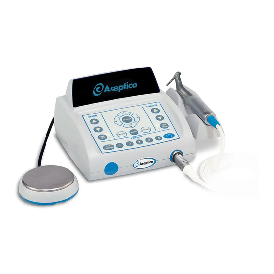
- Page 1 OPERATION MAINTENANCE INSTRUCTION MANUAL AEU-26OS Implant System...
-
Page 2: Table Of Contents
INFORMATION CONCERNING THE ACCURACY AND PRECISION OF THIS PRODUCT MAY BE OBTAINED UPON REQUEST BY CONTACTING ASEPTICO AT THE The AEU-26OS is an electric drive system for instruments ADDRESS SHOWN ON THIS PAGE. and tools used in dentistry for implant procedures. The system includes a wide range of user controls designed to provide precision implant procedures. -
Page 3: Introduction
Your new Aseptico AEU-26OS Implant System is one of the finest units available to the dental profession. The system features a high torque brushless motor, intuitive user Congratulations interface, and an easy to read digital display. These features combine to make the AEU-26OS an exceptionally powerful and convenient system for Implant procedures. -
Page 4: Safety Precautions
• Handpieces should only be attached when the motor has stopped running. WARNING: Do not install where there is a risk of an explosion. The AEU-26OS is not intended for operation in the presence of flammable anesthetics or gases. CAUTION:... - Page 5 CAUTION: Connect mains power cable to a properly grounded outlet only. CAUTION: The AEU-26OS motor is sensitive to shock and may be damaged if dropped or impacted against a hard surface. WARNING: Do not disassemble or alter the AEU-26OS motor, console, or foot switch.
-
Page 6: Setting Up The Unit
SETTING UP THE UNIT: 1. Unpack the Console and accessories (see Fig. 2 - Motor Cradle Figure 1). 2. Install the Motor Cradle: The autoclavable Motor Cradle can be attached to either side CHASSIS of the Console or placed flat on any adjacent CRADLE tabletop surface or tray. - Page 7 5. Connect the Motor/Cord Assembly to the Motor Receptacle on the lower right front of the console (see Figure 1). The motor cord connector and console receptacle are keyed to engage one another. IMPORTANT: Align the red dot on the motor cord connector with the arrow located on the top of the receptacle.
-
Page 8: Quick Start Operation
5. Select the Preset Key corresponding to the 3. Select the handpiece ratio. To calibrate a implant step you are performing. By default, handpiece for the AEU-26OS, the user must the preset buttons are set for the implant first select the ratio. Press the RATIO key and protocol shown in Chart 1, page 7. -
Page 9: Chart 1 - Implant Default Presets
Therefore, it is recommended that on the display, and any percentages thereof, you always use a sterile irrigation wand, such as the Aseptico NWS-9 or other appropriate assumes the use of a well-maintained (per the manufacturer's instructions), high-efficiency irrigation sources, during all highspeed drilling... -
Page 10: Control Panel Functions
CONTROL PANEL FUNCTIONS The intuitive user interface makes it easy to begin using your new AEU-26OS. Advanced features for editing and programming the system are discussed following the control panel descriptions. Fig. 5 - Console Display & Controls OPERATION MODE DISPLAY... - Page 11 30K motor. replace the handpiece ratio in that Preset. The following prompt will display: Fig. 6 - AEU-26OS SPEED RANGES 1,500 - 150,000 Change The Handpiece Ratio For The Current...
- Page 12 Auto-Stop Reached (ASR), Select the desired Preset Key. By default, Maximum (MAX), or Torque the preset buttons are set for the Aseptico Limit Modes. implant series shown in Chart 1 on page 7. a. ASR Mode - For 1:1, 16:1, Note: Pressing and holding a Preset Key or 20:1 ratio handpieces only.
-
Page 13: Advanced Operation
ADVANCED OPERATION: character that is to be changed. Use the After the unit has been set up and the user Up or Down arrow buttons to (YES/NO) has become familiar with the system’s change the character to the desired letter, control panel functions, there are two symbol, or numerical value. -
Page 14: System Setup Menu
ADVANCED OPERATION - Cont’d: SETUP Factory Reset: Are You Sure? Press and hold the CAL/SETUP (YES/NO) Key to enter Setup Options NOTE: Any customized presets will be lost Mode. Press the Up/Down Keys if you Recall Factory Setup. to scroll through the options. Press SELECT key to select the option to a) To keep your customized settings and return to the Setup Options Menu, press... - Page 15 inactivity to conserve power. In Sleep a) SELECT “Cancel” to escape out of this Mode, the lighted Console Display will turn menu and return to previous menu. b) SELECT “On” to enable the Reverse off and the green LEDs above the five Beeper feature and return to previous menu.
-
Page 16: Variable-Speed Foot Control Operation
CONNECTOR AEU-26OS Installation: 1. Attach the Foot Control cable to the connector on the back of the AEU-26OS Console (see Figure 7). Note keyway on connector. Turn locking sleeve clockwise to secure cable to connector. The AEU- 26OS will automatically sense the Foot... - Page 17 5. The center Variable Pedal can be operated in either the ‘Variable’ or ‘On/Off’ modes, AE-7PM FOOT CONTROL depending on which option is selected (Standard Equipment on AEU-26OS System) during Setup (page12). (NOTE: This pedal Fig.10 can also be used to bring the unit out of Sleep Mode.)
-
Page 18: Reprogramming The Unit
REPROGRAMMING THE UNIT 5. The AEU-26OS Display will show the fol- Fig. 11 - Programming Slot lowing messages: NOTE: Pressing the 'NO' key at any time will abort the reprogramming process. Memory Card Detected. Re-program? (YES / NO) • Press the ‘Yes’ key on the Control Panel. -
Page 19: Sterilization
STERILIZATION: WARNING - Sterilize the motor between Motor & Cord Assembly: each patient use. The entire AE-225-30 motor and cord WARNING - Use of a sterilization assembly is fully autoclavable. Loosely coil method or temperatures other than what the motor cord when autoclaving. Avoid are prescribed may damage the motor sharply bending the cord when autoclaving. -
Page 20: Maintenance & Cleaning
MAINTENANCE & CLEANING: HANDPIECES - Thorough cleaning and lubrica- tion of handpieces after each use and before sterilization is very important to ensure proper operation and service life of the handpiece. Follow the instructions provided with the hand- piece for complete maintenance instructions. MOTOR - IMPORTANT! Fig. -
Page 21: Troubleshooting
TROUBLESHOOTING: Problem: Correction: Console does not light up when on: • If Preset LEDs are blinking, press Standby Key on Control Panel or press foot pedal to exit Sleep Mode. • Check console to power connection. • Check fuse. If blown, replace with 1.6A, 250V slo-blow fuse. -
Page 22: Specifications
(50°F) (-4°F) 1013.3 CHANGING THE FUSE: W RNING NOTE: The AEU-26OS features auto-sensing, global voltage compatibility. The fuse indicated is correct for 100V-240V 50/60 Hz line Turn the power off and unplug the unit voltage. before following the steps below. -
Page 23: Symbol Definitions
SYMBOL DEFINITIONS: Authorized European Representative Type B Equipment Standby Switch Dangerous Voltage Footswitch Alternating current Manufacturer Protection Against Dripping Water Fuse Rating Protective Earth (Ground) 250V Preset Step Through Motor Direction Torque Mode Step Through Pump On/Off (Not Activated) Temperature Limitation Serial Number Attention, consult Humidity Limitation... -
Page 24: Warranty
Aseptico's sole obligation under product warranty is (at its sole option and discretion) to repair or replace any defective component or product in part or whole. Aseptico shall be the sole arbiter of such action.
Need help?
Do you have a question about the AEU-26OS and is the answer not in the manual?
Questions and answers