
Subscribe to Our Youtube Channel
Related Manuals for Aseptico AEU-7000L-70V


Summary of Contents for Aseptico AEU-7000L-70V
- Page 1 OPERATION MAINTENANCE INSTRUCTION MANUAL AEU-7000L-70V & AEU-7000L Implant / Endodontic Dental Systems AEU-7000L-70V System...
-
Page 2: Table Of Contents
RX: FEDERAL LAW RESTRICTS THIS DEVICE TO INDICATIONS FOR USE: SALE BY OR ON THE ORDER OF A DENTIST The AEU-7000L-70V & AEU-7000L are drive systems for instruments and tools used in dentistry for implant/surgical INFORMATION CONCERNING THE ACCURACY AND procedures and endodontic procedures. -
Page 3: Introduction
Your new Aseptico AEU-7000L-70V & AEU-7000L Systems are two of the finest dual- function implant/endodontic motor systems available to the dental profession. The systems combine a powerful brushless 40,000 RPM motor with a wide range of handpiece ratios and precision torque controls to make the perfect dental systems for Congratulations both implant and endodontic applications. -
Page 4: Safety Precautions
Important additional information and hints. SAFETY PRECAUTIONS: Aseptico accepts no liability for direct or consequential injury or damage resulting from improper use, arising in particular through the non-observance of the operating instructions, or improper preparation and maintenance of this product. - Page 5 Do not adjust the torque above the supplier-recommended rating or there is a risk of damage to the internal parts of your handpiece (which is not covered under warranty). Aseptico recommends and distributes AHP-85MB-series 20:1 handpieces, which are rated...
-
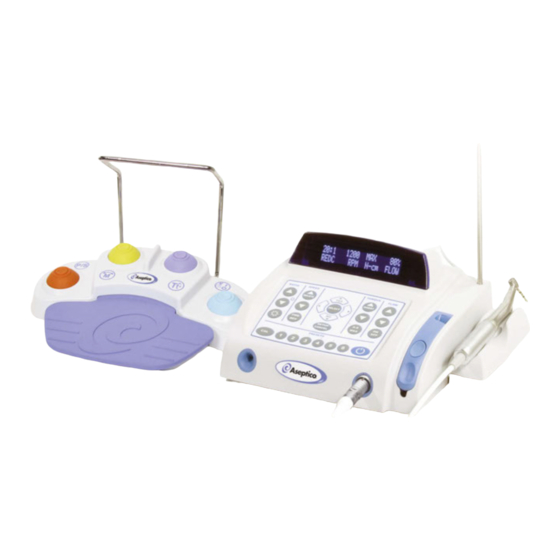
Page 6: Setting Up The Unit
Fig.3 - Setup ELECTRONIC CONTROL IRRIGATION BAG CONSOLE HANGER ROD MULTI-FUNCTION FOOT CONTROL HANDPIECE & MOTOR CALIBRATION ADAPTER STORAGE MOTOR CRADLE & BRACKET DOOR RELEASE BUTTON DYNAMOMETER PORT IRRIGATION MOTOR PUMP DOOR RECEPTACLE CORD CONNECTOR MOTOR CORD STRAIN RELIEF (AEU-7000L-70V System shown) - Page 7 b. Install Pump Tubing Assembly into pump 5. Attach the appropriate "E-Type" handpiece to door as shown in Figure 5. Install tubing the motor as shown in Figure 4. connector into the slot located on the Fig. 4 - Handpiece/Motor Connection back end of pump door.
-
Page 8: Control Panel Functions
CONTROL PANEL FUNCTIONS: 1. Main Power Switch: press the foot pedal to return the System to the last state used. Located on back of console (see Figure 2). Controls main power On / Off to the console. 3 Mode Select Button: The System will initialize with Implant Selects Implant or Endodontic Preset-1 active when: unit is first turned On;... -
Page 9: Speed Ranges
5 Handpiece Ratio Selector: “20:1”, to “20.7:1”), indicating the precise ratio Allows user to select ratio of hand- measured. This also serves as an indicator piece. Ensures accurate display of that the handpiece has been calibrated. speed and torque levels. 6 Speed: a. - Page 10 CONTROL PANEL FUNCTIONS - Cont’d: 9 Torque Modes (A-S / MAX): maximum level. The handpiece will only Allows the user to select from operate up to this specified torque level. No incremental adjustments are allowed one of three torque control modes: Auto-Stop (Implant when in “MAX”...
- Page 11 12 INSERT: the following procedures: Allows user to enter a blank Preset 1 - Site Preparation: space into characters when Preset 2 - Pilot Drill: editing the Preset button Preset 3 - Finish Drill / Reamer: settings on the display. Preset 4 - Tap Forward: 13 Display Edit &...
- Page 12 CONTROL PANEL FUNCTIONS - Cont’d: 16 MOTOR LED ON/OFF & ADJUSTMENT: Turns motor LED illumination On/Off and allows adjustment of intensity, from 10%, to 100%. LED INTENSITY ‘UP’ BUTTON Press then release the motor LED button to turn LED 'On' or 'Off'.
-
Page 13: Operation
OPERATION: System to the last state used. NOTE: The GETTING STARTED: After the unit has been unit is in Sleep Mode when the Preset set up and the user has become familiar with LEDs blink consecutively. the System’s control panel functions, there are two different modes that can be used to Manual Mode: begin operation:... - Page 14 OPERATION - Cont’d: level reaches 75% and 100% of the Auto- buttons to select desired LED intensity in Stop limit. Auto-Stop is the suggested 10% increments. Press the LED button once mode when tapping and threading to exit adjustment mode. implants.
- Page 15 Part-2 Dyno Calibration Procedure: Fig.7 - Adapter Installation If a reduction handpiece passes the Free Run calibration, the System automatically advances to the Part-2 Dyno calibration procedure. The following message will be displayed: Put Handpiece Into Dyno CALIBRATION ADAPTER Press 1> Next 3>...
-
Page 16: Presets - Implant Mode
OPERATION IMPLANT Presets Step 2: Press and hold any of the Preset buttons 1 through 6, to save the new, modified settings into that particular button. Step 3: The six preset memory buttons are A display prompt then asks the user: preprogrammed at the factory with the Preset - (X) default Implant Presets shown in Chart 1,... - Page 17 Important: When the factory default Note: To enter a blank space into the text line, place the cursor settings are restored or recalled, or when under the character and press the unit has been reprogrammed with new the INSERT button. software, any previous user-defined settings will be overwritten.
-
Page 18: Presets - Endodontic Mode
OPERATION ENDODONTIC Presets 13.Editing Endodontic Presets: All six preset memory buttons can be modified by the user with new files and operating parameters at any time. These new settings will overwrite the existing The six preset memory buttons are settings, including factory defaults. In preprogrammed at the factory with the addition, the new Preset Files’... - Page 19 Step 4: Example: Press SELECT button to save “FILE NAME YYZ” settings or CANCEL out of the Press SELECT To Save menu. Step 5: Repeat Steps 8 & 9 for all remaining text characters that require edits. A new Preset entitled “User Defined Preset”...
- Page 20 OPERATION ENDODONTIC Presets, Cont’d: The scrolling “Help” message IMPORTANT: Whenever the unit’s factory instructs the user to press the default settings are recalled, or when the Up/Down arrow buttons to view unit has been reprogrammed with new two different menu choices: software, the default File Series will be restored to all the Preset buttons.
- Page 21 OPERATION Chart 2 ENDODONTIC Default File Presets IMPORTANT Preset Button 1: PathFile The console will drive DENTSPLY Tulsa Dental Specialties PathFile All Files ® the files as close to the File #1: PathFile (All Files) library requested speed and torque as the Preset Button 2: ProTaper Next handpiece parameters DENTSPLY Tulsa Dental Specialties ProTaper Next™...
-
Page 23: System Setup
SYSTEM SETUP warns the user with an audible signal The SETUP Program allows the when a specified Torque Limit is reached. user to select/configure setup Warning signals are provided differently, options via display prompts. The depending upon which operating mode is option selections and corresponding activated. - Page 24 SYSTEM SETUP - Cont'd b. To enable a 30-minute delay, press 4. Auto Stop Mode (for Endo Mode Only): Preset Button #2. When the Auto Stop Reverse (ASR) feature is enabled, rotation of the c. To disable Sleep Mode (Display stays handpiece will automatically stop and on), press Preset Button #3.
-
Page 25: Foot Switch Description & Operation
VARIABLE-SPEED FOOT CONTROL OPERATION The AE-70V2 Variable-Speed Foot Control Fig.10 - Variable-Speed Foot Control comes as standard equipment on the HANDLE AEU-7000L-70V System and as an option (Removable) on the AEU-7000L System. The AE-70V2 can control motor speed, direction, torque, TORQUE MODE and turn the pump On/Off. - Page 26 VARIABLE-SPEED FOOT CONTROL - Cont'd Handle Installation/Removal: Note: The following message will appear briefly whenever any Endo Preset is 7. The Foot Switch Handle may be installed to accessed for the first time, or after factory allow the user to reposition or move the defaults have been restored: Foot Control more easily.
-
Page 27: Reprogramming The Unit
Programming Successful. devices. These cards, available from Eject Card. Aseptico, enable a user to update software or replace existing software that might • Press the card inward slightly, then have been accidentally erased or release it to eject it. -
Page 28: Sterilization Procedure
2) Thoroughly clean the device with a moist autoclavable. cloth or towel to remove any remaining signs of debris. NOTE: Call Aseptico Inc. at 1-800-426-5913 Sterilize for any questions or clarifications on this sterilization procedure. 3) Select one of the three following sterilization methods (A. -
Page 29: Specifications
SPECIFICATIONS: be damaged. It should not Fig. 16 Console Dimensions: 9.98”W x 9.42”L x 5.10”H be exposed to dust and (25.3 cm x 23.9 cm x 12.9 cm) debris. Excessive dust Console Weight: 7.3 lbs (3.3kg) and debris may cause a Power: 100-240V drastic decrease in optical... -
Page 30: Troubleshooting
Then, grasp the connector body near the red dot and pull the connector straight out of the motor receptacle. CHANGING THE FUSE: W RNING NOTE: The AEU-7000L-70V & AEU-7000L feature auto-sensing, global voltage compatibility. The fuse indicated is correct for Turn the power off and unplug the unit 100V-240V 50/60 Hz line voltage. -
Page 31: Symbol Definitions
SYMBOL DEFINITIONS: Authorized European Attention, consult Representative accompanying documents Type BF Equipment Standby Switch Dangerous Voltage Footswitch Alternating current Do Not Throw Into Trash Protection Against Dripping Water Manufacturer Protective Earth (Ground) Fuse Rating Motor Direction Preset Step Through Pump On/Off Torque Step Through Temperature Limitation Atmospheric Pressure Limitation... -
Page 32: Warranty
Aseptico's sole obligation under product warranty is (at its sole option and discretion) to repair or replace any defective component or product in part or whole. Aseptico shall be the sole arbiter of such action.
Need help?
Do you have a question about the AEU-7000L-70V and is the answer not in the manual?
Questions and answers