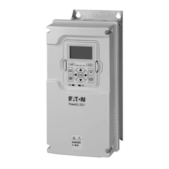
Eaton PowerXL DG1 Series Communications Manual

Eaton PowerXL DG1 Series Communications Manual

Hide thumbs Also See for PowerXL DG1 Series:
Table of Contents

Advertisement

PowerXL DG1 Series VFD
Effective September 2016
Supersedes May 2014
Communication manual

Advertisement

Table of Contents
loading
Need help?

Need help?

Do you have a question about the PowerXL DG1 Series and is the answer not in the manual?

Questions and answers

Subscribe to Our Youtube Channel

Summary of Contents for Eaton PowerXL DG1 Series

  • Page 1 PowerXL DG1 Series VFD Effective September 2016 Supersedes May 2014 Communication manual...
  • Page 2 CONTENTS OF THIS DOCUMENT SHALL NOT BECOME PART OF OR MODIFY ANY CONTRACT BETWEEN THE PARTIES. In no event will Eaton be responsible to the purchaser or user in contract, in tort (including negligence), strict liability, or otherwise for any special, indirect, incidental, or consequential damage or loss whatsoever, including but not limited to...
  • Page 3 PowerXL DG1 Series VFD Support services Support services The goal of Eaton is to ensure your greatest possible satisfaction with the operation of our products. We are dedicated to providing fast, friendly, and accurate assistance. That is why we offer you so many ways to get the support you need.
  • Page 4: Table Of Contents

    BACnet overview ..........74 POWERXL DG1 SERIES VFD MN040010EN—September 2016 www.eaton.com...
  • Page 5 Fault codes ............168 POWERXL DG1 SERIES VFD MN040010EN—September 2016 www.eaton.com...
  • Page 6 Figure 41. General state diagram ........POWERXL DG1 SERIES VFD MN040010EN—September 2016 www.eaton.com...
  • Page 7 Figure 51. Network state machine ........135 POWERXL DG1 SERIES VFD MN040010EN—September 2016 www.eaton.com...
  • Page 8 Table 43. Request to read exception status ....... . . 25 viii POWERXL DG1 SERIES VFD MN040010EN—September 2016 www.eaton.com...
  • Page 9 Table 88. Instance 111 (output) length = 20 bytes ......POWERXL DG1 SERIES VFD MN040010EN—September 2016 www.eaton.com...
  • Page 10 Table 132. CANopen board status LED (D10) (Red LED) ......102 Table 133. CANopen module status—Error LED (D2-Red LED) ....102 POWERXL DG1 SERIES VFD MN040010EN—September 2016 www.eaton.com...
  • Page 11 Table 177 . Identity object, class 0x01 ........137 Table 178. Bit definitions for status instance attribute of identity object ... . 138 POWERXL DG1 SERIES VFD MN040010EN—September 2016 www.eaton.com...
  • Page 12 Table 191. Fault code list ..........168 POWERXL DG1 SERIES VFD MN040010EN—September 2016 www.eaton.com...
  • Page 13: Before Commencing The Installation

    DIP or failure. charge in the capacitors, these parts may still be live This should not cause dangerous operating states even after disconnection. Fit appropriate warning signs xiii POWERXL DG1 SERIES VFD MN040010EN—September 2016 www.eaton.com...
  • Page 14: Definitions And Symbols

    Contact with this performing maintenance voltage is extremely dangerous and may cause death Be sure equipment is properly earthed • or severe injury. Wear safety glasses whenever working on electronic • controllers or rotating machinery POWERXL DG1 SERIES VFD MN040010EN—September 2016 www.eaton.com...
  • Page 15 A hard Before applying power to this drive, make sure that copy of this information may be ordered from Eaton the front and cable covers are closed and fastened to literature fulfillment.
  • Page 16 Do not attempt to install or remove the MOV or EMC • of the equipment grounding conductor must be at least screws while power is applied to the drive’s input 10 mm2 Cu. Drive requires that only copper conductor should terminals. be used. POWERXL DG1 SERIES VFD MN040010EN—September 2016 www.eaton.com...
  • Page 17: Motor And Equipment Safety

    For more technical information, contact the factory or your local Eaton sales representative. xvii POWERXL DG1 SERIES VFD MN040010EN—September 2016 www.eaton.com...
  • Page 18 • norme CEI/EN 60204-1 doivent être efficace dans tous les modes de fonctionnement des dispositifs d’automatisation. Le déverrouillage des dispositifs d’arrêt d’urgence ne doit pas entraîner un redémarrage xviii POWERXL DG1 SERIES VFD MN040010EN—September 2016 www.eaton.com...
  • Page 19 MISE EN GARDE peut, si elle n’est pas évitée, entraîner des conséquences graves. Des mesures de sécurité importantes sont décrites dans les MISES EN GARDE (ainsi que dans les AVERTISSEMENTS). POWERXL DG1 SERIES VFD MN040010EN—September 2016 www.eaton.com...
  • Page 20 Ce support doit être conservé avec cet appareil à tout précaution peut entraîner la mort ou des blessures graves. moment. Une copie papier de ces informations peut être commandée auprès du service de documentation Eaton. POWERXL DG1 SERIES VFD MN040010EN—September 2016 www.eaton.com...
  • Page 21 Les entrées anti-rebond ne sont pas permises dans le schéma du circuit de sécurité. Des disjoncteurs de courant résiduel (RCD) ne peuvent être installés qu’entre le réseau de courant alternatif et l’entraînement. POWERXL DG1 SERIES VFD MN040010EN—September 2016 www.eaton.com...
  • Page 22 S’assurer que les bornes de sortie de l’entraînement (U, V, et CEM lorsque l’alimentation est appliquée aux bornes W) ne sont pas connectées à l’alimentation secteur, ce qui d’entrée de l’entraînement pourrait causer de graves dommages à l’entraînement. xxii POWERXL DG1 SERIES VFD MN040010EN—September 2016 www.eaton.com...
  • Page 23 E/S de l’entraînement. Le nombre de cycles de charge représentant commercial Eaton local. maximum permis des condensateurs CC (c’est-à-dire les mises sous tension par application de puissance) est de cinq en dix minutes. xxiii POWERXL DG1 SERIES VFD MN040010EN—September 2016 www.eaton.com...
  • Page 24: Powerxl Series Overview

    To activate the real time clock (RTC) functionality in the This series overview describes the purpose and contents of PowerXL DG1 Series VFD, the RTC battery (already mounted this manual, the receiving inspection recommendations and in the drive) must be connected to the control board.
  • Page 25: Rating Label

    Powerxl series overview Rating label General information The DGI Series Drives from Eaton’s electrical business provides a wide selection of option boards to increase the Figure 2. Rating label number and type of control inputs and outputs (I/O) and communication interfaces to provide the versatility required for today’s demanding motor control applications.
  • Page 26: Option Card Slots

    Optional Card A Optional Card B Control I/O Terminals RS-485 Termination Resistor Removable MOV Screw Removable EMC Screw Motor Ground Clamp Location Line Ground Clamp Location Grounding Strap Location Grounding Strap Location Line Side Motor POWERXL DG1 SERIES VFD MN040010EN—September 2016 www.eaton.com...
  • Page 27: Installing Dg1 Option Board

    Table 2. Wire sizes Wire type Wire size Terminal torque Solid Cu –90 °C 12–28 AWG (0.2~2.5 mm 4.5 in-lb (0.5 Nm) Stranded Cu –90 °C 12–30 AWG (0.2~2.5 mm 4.5 in-lb (0.5 Nm) POWERXL DG1 SERIES VFD MN040010EN—September 2016 www.eaton.com...
  • Page 28: Emc Directive

    CANopen = CANopen SPR = Spare part SWD = SmartWire KEY = Keypad See Volume 6, CA08100007E, CBL = Cable Tab 2, PowerXL DG1 Accessories for full offering ote:  Will be available 2017 . POWERXL DG1 SERIES VFD MN040010EN—September 2016 www.eaton.com...
  • Page 29: Modbus Rtu On-Board Communications

    AFD via the communication parameters. The electrical connection between master and the slaves connected in parallel are implemented via the serial interface A-B (A = negative, B = positive) with a shielded RS-485 twisted pair cable. POWERXL DG1 SERIES VFD MN040010EN—September 2016 www.eaton.com...
  • Page 30: Modbus Rtu Specifications

    Electrical Isolation Communications Table 6. Communications Item Description As described in “Modicon Modbus Protocol Modbus RTU Reference Guide” found at. http.//public.modicon.com/ 9600,19200,38400,57600,115200 Baud Rate 1 to 247 Addresses Figure 8. Termination resistor and shielding POWERXL DG1 SERIES VFD MN040010EN—September 2016 www.eaton.com...
  • Page 31: Commissioning

    0 = None, 2 Stop Bits P20.2.4 1 = Odd, 1 Stop Bit 2 = Even, 1 Stop Bit P20.2.5 Protocol status 0 = Initial 1 = Stopped 2 = Operational 3 = Faulted POWERXL DG1 SERIES VFD MN040010EN—September 2016 www.eaton.com...
  • Page 32: Modbus Communication Standards

    When the slave sends its response, it places its own address in this address field of the response to let the master know which slave is responding. POWERXL DG1 SERIES VFD MN040010EN—September 2016 www.eaton.com...
  • Page 33: Table 8. Functions

    Number of coils Low 0x03 Two kinds of checksum are used for standard Modbus CRC High 0x7E networks. The error checking field contents depend upon CRC Low 0x25 the transmission method that is being used. POWERXL DG1 SERIES VFD MN040010EN—September 2016 www.eaton.com...
  • Page 34: Table 10. Request To Read Discrete Inputs

    Starting address 0x07D0 hex (= 2000) Start address Low 0xD0 Number of Input Registers Number of Input 0x00 0x0003 hex (= 3) Registers High Number of Input 0x03 Registers Low CRC High 0xB2 CRC Low 0x25 POWERXL DG1 SERIES VFD MN040010EN—September 2016 www.eaton.com...
  • Page 35: Table 16. Request To Write Single Register

    The binary outputs in the previous example corre- spond to the outputs in the following way. Table 18. Binary bits and corresponding outputs Output 26 25 24 23 22 21 20 19 — — — — — 28 27 POWERXL DG1 SERIES VFD MN040010EN—September 2016 www.eaton.com...
  • Page 36: Table 20. Index Table

    (e.g., Torque reference). With the Status Word (SW) read by the Master, the status of the device can be seen. Actual Value (ACT) and PD1–PD8 show the other actual values. POWERXL DG1 SERIES VFD MN040010EN—September 2016 www.eaton.com...
  • Page 37: Table 23. Fieldbus Basic Input Table

    See Process Data IN section for setup. 10–15 Not in use Not in use Fb general control word The DG1 does not use the FB General Control Word. The main control word is used to provide commands to the drive. POWERXL DG1 SERIES VFD MN040010EN—September 2016 www.eaton.com...
  • Page 38: Table 27. Fieldbus Basic Output Table

    Faulted — Warning — Ref. frequency not reached Ref. frequency reached Bypass activated Bypass not activated Run Enable Run disable Not in use Not in use Not In use 9–15 Not in use POWERXL DG1 SERIES VFD MN040010EN—September 2016 www.eaton.com...
  • Page 39: Table 32. Process Data Out

    1. Set FB control word (Modbus Address 42000) value to 0hex to 1hex 6. DG1 status is STOP 2. DG1 status is RUN 3. Set FB Speed reference (Modbus Address 42002) value to 5000 (= 50.00%) POWERXL DG1 SERIES VFD MN040010EN—September 2016 www.eaton.com...
  • Page 40: Modbus Tcp On-Board Communications

    Modbus/TCP , and it is only used when one IP address indicator in the sequence, followed by any Network Status stands for several endpoints. indicators present. After completion of this power up test, the indicator(s) will turn to a normal operational state. POWERXL DG1 SERIES VFD MN040010EN—September 2016 www.eaton.com...
  • Page 41: Figure 11. Module And Network Status

    Exclusive Owner connections are established. Steady Red Major fault PowerXL has detected a non-recoverable major fault. Self-test PowerXL is performing its power up testing. Flashing Green/Red  Flash rate is 1 flash per second. POWERXL DG1 SERIES VFD MN040010EN—September 2016 www.eaton.com...
  • Page 42: Commissioning

    IP Address Mode 1500 0 = Static IP P20.3.1 1 = DHCP with AutoIP Active IP Address 1507 P20.3.2 Active Subnet Mask 1509 P20.3.3 Active Default Gateway 1511 P20.3.4 MAC Address 1513 P20.3.5 POWERXL DG1 SERIES VFD MN040010EN—September 2016 www.eaton.com...
  • Page 43 IP port, a fieldbus error is generated immediately. Modbus RTU. This Unit Identifier is used to communicate via devices such as bridges, routers and gateways that use a single IP address to support multiple independent Modbus end units. POWERXL DG1 SERIES VFD MN040010EN—September 2016 www.eaton.com...
  • Page 44: Figure 14. Static Ip Mode

    Change in IP address mode will require PowerXL to mode configurations will be loaded. power cycle to get this change effective. Also ensure device MAC address (Keypad menu. P20.3.5) Figure 14. Static IP mode POWERXL DG1 SERIES VFD MN040010EN—September 2016 www.eaton.com...
  • Page 45: Figure 15. Static Ip Address

    Modbus TCP On-Board communications 2. Using PowerXL drive keypad, set the IP address in the PowerXL EIP to the desired address setting by. a. Setting Static IP Address Figure 15. Static IP address POWERXL DG1 SERIES VFD MN040010EN—September 2016 www.eaton.com...
  • Page 46: Figure 16. Static Subnet Mask

    Modbus TCP On-Board communications b. Setting Static Subnet Mask Figure 16. Static subnet mask c. Setting Static Default Gateway Figure 17. Static default gateway POWERXL DG1 SERIES VFD MN040010EN—September 2016 www.eaton.com...
  • Page 47: Figure 18. Modbus Tcp Unit Id

    4. Using PowerXL drive keypad, read “Active IP Address” (Keypad menu. P20.3.2), “Active Subnet Mask” (Keypad menu. P20.3.3), “Active Default Gateway” (Keypad menu. P20.3.4) parameters to ensure that IP address has been set to desired IP address. POWERXL DG1 SERIES VFD MN040010EN—September 2016 www.eaton.com...
  • Page 48: Modbus Communication Standards

    CRC Low 0x83 Start address Low 0xD0 Number of Holding Registers Number of Holding 0x00 0x0003 hex (= 3) Registers High Number of Holding 0x03 Registers Low CRC High 0x07 CRC Low 0xE5 POWERXL DG1 SERIES VFD MN040010EN—September 2016 www.eaton.com...
  • Page 49: Table 45. Request To Write Single Coil

    The binary outputs in the previous example correspond to the outputs in the following way. Table 48. Binary bits and corresponding outputs Output 26 25 24 23 22 21 20 19 — — — — — — 28 27 POWERXL DG1 SERIES VFD MN040010EN—September 2016 www.eaton.com...
  • Page 50: Table 51. Process Data Slave → Master (Max. 22 Bytes)

    (e.g., Torque reference). With the StatusWord (SW) read by the Master, the status of the device can be seen. Actual Value (ACT) and PD1–PD8 show the other actual values. POWERXL DG1 SERIES VFD MN040010EN—September 2016 www.eaton.com...
  • Page 51: Table 54. Binary Bits And Corresponding Outputs

    (P1.2). This value has 2 decimal places in it. Process data in 1 to 8 Process Data In values 1 to 8 can be used in applications for various purposes. See below Process Data IN section for setup. POWERXL DG1 SERIES VFD MN040010EN—September 2016 www.eaton.com...
  • Page 52: Table 57. Fieldbus Basic Output Table

    14 13 12 11 10 MSB — — — — — — — — — — — — — — LSB This is the Actual Speed of the motor.This value comes back in the form of % POWERXL DG1 SERIES VFD MN040010EN—September 2016 www.eaton.com...
  • Page 53: Table 62. Process Data Out

     Process Data IN7 0.01% 2010  Process Data IN8 0.01% 2011  ote:  Process Data IN1 through Process Data IN8 change based off the selected application. See Appendix B for layout. POWERXL DG1 SERIES VFD MN040010EN—September 2016 www.eaton.com...
  • Page 54: Ethernet/Ip On-Board Communications

    Overlapping IP addresses can cause conflicts between appliances. For more information about setting IP addresses, see “Manual IP Address Configuration” on Page 21. EtherNet/IP is a trademark of the Open DeviceNet Noee: Vendor Association (ODVA). POWERXL DG1 SERIES VFD MN040010EN—September 2016 www.eaton.com...
  • Page 55: Hardware Specifications

    After completion of this power up test, the indicator (s) will turn to a normal operational state. Yellow LED on the ethernet jack is OFF when link speed is 10 mbps POWERXL DG1 SERIES VFD MN040010EN—September 2016 www.eaton.com...
  • Page 56: Figure 19. Module And Network Status

    Exclusive Owner connections are established. Steady red Duplicate IP address PowerXL has detected a Duplicate IP. Flashing green/red Self-test PowerXL is performing its power on self test. Flash rate is 1 flash per second. POWERXL DG1 SERIES VFD MN040010EN—September 2016 www.eaton.com...
  • Page 57: Ethernet/Ip Overview

    CIP provides users with unified communication architecture throughout the manufacturing enterprise. 2. Machine to machine (industrial environment, fast communication) Industrial Environment Figure 21. Machine oN machine (indusorial envirNnmeno, faso cNmmunicaoiNn) POWERXL DG1 SERIES VFD MN040010EN—September 2016 www.eaton.com...
  • Page 58: Figure 22. Cat-5E Cable

    192.168.1.1 1505 P20.3.9 EtherNet/IP Protocol Status 0 = Off 1 = Operational 2 = Faulted P20.3.10 Connection Limit P20.3.19 EIP Fault Response 2518 0 = In Fieldbus Control 1 = in all Control POWERXL DG1 SERIES VFD MN040010EN—September 2016 www.eaton.com...
  • Page 59: Commissioning

    Defines how much time can pass from the last received message from the client device before fieldbus fault is generated. Default communication timeout is 10seconds. Noee: If the network cable is broken from PowerXL EtherNet/IP slot, a fieldbus error is generated immediately. POWERXL DG1 SERIES VFD MN040010EN—September 2016 www.eaton.com...
  • Page 60: Figure 23. Static Ip Mode

    Change in IP address mode will require PowerXL to configurations will be loaded. power cycle to get this change effective. Also ensure device MAC address (Keypad menu. P20.3.5) Figure 23. Soaoic IP mNde POWERXL DG1 SERIES VFD MN040010EN—September 2016 www.eaton.com...
  • Page 61: Figure 24. Static Ip Address

    EtherNet/IP On-Board communications 2. Using PowerXL drive keypad, set the IP address in the PowerXL EIP to the desired address setting by: a. Setting Static IP Address Figure 24. Soaoic IP address POWERXL DG1 SERIES VFD MN040010EN—September 2016 www.eaton.com...
  • Page 62: Figure 25. Static Subnet Mask

    4. Using PowerXL drive keypad, read “Active IP Address” (Keypad menu. P20.3.2), “Active Subnet Mask” (Keypad menu. P20.3.3), “Active Default Gateway” (Keypad menu. P20.3.4) parameters to ensure that IP address has been set to desired IP address. POWERXL DG1 SERIES VFD MN040010EN—September 2016 www.eaton.com...
  • Page 63: Plc Programming

    Select windows Start → All Programs. Open RSLogix 5000. From the Tools drop-down menu, select EDS Hardware Installation Tool to install the PowerXL Drive EtherNet/ IP EDS file. This file can be downloaded from the Eaton website. POWERXL DG1 SERIES VFD MN040010EN—September 2016 www.eaton.com...
  • Page 64 EtherNet/IP On-Board communications Select “New” from “File” menu. New controller window will pop-up. Select the controller and assign unique name. POWERXL DG1 SERIES VFD MN040010EN—September 2016 www.eaton.com...
  • Page 65 EtherNet/IP On-Board communications Press OK. Right-click on Ethernet. Select “New Module. ” Noee: PC on which RSLogix (master) is running and PowerXL device (slave) should be connected in same network. POWERXL DG1 SERIES VFD MN040010EN—September 2016 www.eaton.com...
  • Page 66 EtherNet/IP On-Board communications “Select Module Type” window will pop-up. Select “PowerXL DG1” (use filter to search PowerXL from catalog). POWERXL DG1 SERIES VFD MN040010EN—September 2016 www.eaton.com...
  • Page 67 You must change the class1 connection from provided default option by using “Change” button available on “New Module” window. This can also be done after adding the device under Ethernet by double-clicking on it. POWERXL DG1 SERIES VFD MN040010EN—September 2016 www.eaton.com...
  • Page 68 EtherNet/IP On-Board communications Choose the INT data type then select /IO connection from the provided list. After selecting desired I/O assembly instance connection, information related to it will appear. POWERXL DG1 SERIES VFD MN040010EN—September 2016 www.eaton.com...
  • Page 69 EtherNet/IP On-Board communications After selecting the I/O connection, click “OK. ” For this example, I/O connection ASM23OT-73TO will be used. The module definition window will then look as follows. POWERXL DG1 SERIES VFD MN040010EN—September 2016 www.eaton.com...
  • Page 70 EtherNet/IP On-Board communications After pressing “OK, ” the following warning will pop-up. Press “Yes. ” Warning snapshot. POWERXL DG1 SERIES VFD MN040010EN—September 2016 www.eaton.com...
  • Page 71 Then select “OK” on the New Module Window and the PowerXL drive will be added to the EtherNet/IP Network on the left, in this case under the CompactLogix EtherNet/IP master port as shown. Close the Select Module Type window or add more devices to the Network. POWERXL DG1 SERIES VFD MN040010EN—September 2016 www.eaton.com...
  • Page 72 Eaton EtherNet/IP products. The imported tags will match the layouts for the I/O assemblies chosen and displayed later in this section and can be used directly in your programs. This tool and a user manual can be downloaded from the Eaton website at the following link: www.eaton.com/software...
  • Page 73: Table 69. List Of Object Classes

    MPFC parameter object Please refer to Appendix A 0xF5 TCP/IP Interface Object CIP required object 0x02 Message router object Communication object 0xF4 Port object Communication object 0xF6 Ethernet link object CIP required object POWERXL DG1 SERIES VFD MN040010EN—September 2016 www.eaton.com...
  • Page 74: Table 70. Services Supported By Object Classes

    1 byte length indicator) REAL 32-bit floating point value SHORT_STRING Character string (1 byte per character, 1 byte length indicator) Table 72. CNnsorucoed daoa oypes Type Code Description Abbreviated array type encoding Formal structure type encoding POWERXL DG1 SERIES VFD MN040010EN—September 2016 www.eaton.com...
  • Page 75: Table 74. Identity Object

    Product code UINT 0x3000 Revision STRUCT of Major revision USINT Minor revision USINT Status WORD 0x34–Default Serial number UDINT Product name SHORT_STRING PowerXL DG1 Insoance services Get_attributes_all Reset Reset type 0 & 1 Get_attribute_single POWERXL DG1 SERIES VFD MN040010EN—September 2016 www.eaton.com...
  • Page 76: Table 75. Connection Manager Object

    Open format rejects UINT Open resource rejects UINT Open other rejects UINT Close requests UINT Close format requests UINT Close other requests UINT Connection timeouts UINT Insoance services Get_attributes_all Get_attribute_single Forward_close Unconnected_send Forward_open POWERXL DG1 SERIES VFD MN040010EN—September 2016 www.eaton.com...
  • Page 77: Table 76. Tcp/Ip Interface Object

     Set service is applicable only in Static IP addressing Mode. Attribute configuration control supports only value 0 Noee: (device is using configuration values that are stored in non-volatile memory). Attribute host name is used just for information purposes. POWERXL DG1 SERIES VFD MN040010EN—September 2016 www.eaton.com...
  • Page 78: Table 77 . Ethernet Link Object

    Forced interface speed UINT Interface type USINT Interface state USINT Admin state USINT Get/Set 01 (Other value write is invalid) Interface label Short String ASCII code of “PowerXL DG1” Insoance services Get_attribute_all Set_attribute_single Get_attribute_single POWERXL DG1 SERIES VFD MN040010EN—September 2016 www.eaton.com...
  • Page 79 Array of UINT 04 00 Maximum ID class attribute USINT 07 00 Maximum ID instance attribute USINT 04 00 Class services Get_attribute_single Insoance aooribuoes Data ARRAY of BYTES Get/Set Insoance services Set_attribute_single Get_attribute_single POWERXL DG1 SERIES VFD MN040010EN—September 2016 www.eaton.com...
  • Page 80: Table 79. Motor Data Object

    Squirrel cage induction motor (7) Second rated current UINT-NV Get/Set 120,1,5000 Second rated voltage UINT-NV Get/Set 380,180,690 Second rated frequency UINT-NV Get/Set 50,30,400 Pole count UINT 4,1,8 Second base speed UINT-NV Get/Set 1440,300,20000 Insoance services Get_attribute_single Set_attribute_single POWERXL DG1 SERIES VFD MN040010EN—September 2016 www.eaton.com...
  • Page 81: Table 80. Control Supervisor Object

    10 sec 0-60sec Insoance Services Get_attribute_single Set_attribute_single Reset (Type 0) Type 0  See Appendix C for list of Fault Codes. Noee: When both Run (Run1 & Run2) attributes set, then no action. POWERXL DG1 SERIES VFD MN040010EN—September 2016 www.eaton.com...
  • Page 82: Figure 27 . State Transition Diagram

    EtherNet/IP On-Board communications Figure 27. Soaoe oransioiNn diagram POWERXL DG1 SERIES VFD MN040010EN—September 2016 www.eaton.com...
  • Page 83: Table 81. Motor Data Object

    UINT-NV Get/Set 468,1,46875 Decel time 2 UINT-NV Get/Set 468,1,46875 Time scale SINT-NV Get/Set 6,0,127 Insoance services Defaulo Get_attribute_single Set_attribute_single Final Accel Time = Accel Time 1 x (2 to power Time Scale). Noee: POWERXL DG1 SERIES VFD MN040010EN—September 2016 www.eaton.com...
  • Page 84: Table 82. Vendor Specific Objects

    Insoance aooribuoes Varies for different objects Insoance services Get_attribute_single Set_attribute_single All the drive parameters given in the application Noee: manual are accessible using the vendor parameter object. See Appendix A for instance values. POWERXL DG1 SERIES VFD MN040010EN—September 2016 www.eaton.com...
  • Page 85 In Freq. control—Process Ref is Process Data IN8 (Analog Output 1, reading the actual output current.). In Torque control—Process Ref is Process Data IN1 (Torque Reference) Based on selection of AO, process reference value will be sent on AO out. POWERXL DG1 SERIES VFD MN040010EN—September 2016 www.eaton.com...
  • Page 86: Table 87 . Instance 101 (Output) Length = 8 Bytes

    Speed Reference commands for Instances 20, 21, 23, and 101 are set up to send the RPM value. This value is sent based off the Motor Nameplate setting provided in the drive. This would be the direct RPM value written. POWERXL DG1 SERIES VFD MN040010EN—September 2016 www.eaton.com...
  • Page 87: Table 88. Instance 111 (Output) Length = 20 Bytes

     This is the reference1 to the frequency converter. Used normally as Speed reference. The allowed scaling is 0 to 10000. In the application, the value is scaled in percentage of the frequency area between set minimum and maximum frequency. (0 = 0.00%–10000 = 100.00%). POWERXL DG1 SERIES VFD MN040010EN—September 2016 www.eaton.com...
  • Page 88: Table 89. Instance 70 (Input) Length = 4 Bytes

     Refer “State transition diagram,” provided under “Control Supervisor Object” and “Drive State” table specified at end of “Input Instances” section. Drive State 0x00 DN_NON_EXISTANT 0x01 DN_STARTUP 0x02 DN_NOT_READY 0x03 DN_READY 0x04 DN_ENABLED 0x05 DN_STOPPING 0x06 DN_FAULT_STOP 0x07 DN_FAULTED POWERXL DG1 SERIES VFD MN040010EN—September 2016 www.eaton.com...
  • Page 89: Table 91. Instance 73 (Input) Length = 6 Bytes

    (0 = 0.00%–10000 = 100.00%). Noee: See info on Assembly 101 for varying values in the Process Data Out 1 and Process Data Out 2 Bytes. See Appendix B on default Process Data info. POWERXL DG1 SERIES VFD MN040010EN—September 2016 www.eaton.com...
  • Page 90: Table 94. Instance 117 (Input). Eip Drive Status Length = 34 Bytes

    (0 = 0.00%–0000 = 100.00%).  The RPM Speed Actual is the actual speed of the motor. The unit is RPM. Noee: See Appendix B for Process Data Value defaults. POWERXL DG1 SERIES VFD MN040010EN—September 2016 www.eaton.com...
  • Page 91: Table 95. Instance 127 (Input). Eip Drive Status Length = 20 Bytes

     This is the actual value from the frequency converter. The value is between 0 and 10000. In the application, the value is scaled in percentage of frequency area between set minimum and maximum frequency. (0 = 0.00%–10000 = 100.00%). POWERXL DG1 SERIES VFD MN040010EN—September 2016 www.eaton.com...
  • Page 92: Bacnet Ms/Tp-On-Board Communication

    Your G-Max HVAC drive is equipped with BACnet support as 76800, 115200 standard. BACnet MS/TP connections The control board is located inside the control unit of the DG1 Series Drive. Figure 28. Principal example diagram POWERXL DG1 SERIES VFD MN040010EN—September 2016 www.eaton.com...
  • Page 93: Figure 29. Stripping The Cable

    4. Then connect the cable to its appropriate terminals on See also step 8 below. G-Max drive standard terminal block, terminals A and B (A = negative, B = positive). See illustration below. POWERXL DG1 SERIES VFD MN040010EN—September 2016 www.eaton.com...
  • Page 94: Figure 33. Rs-485 Bus Termination Setup

    See illustration below. See also step 6 above. We recommend that the first device on the bus terminated is the Master device. BACnet MS/TP bus termination Figure 34. BACneo bus oerminaoiNn POWERXL DG1 SERIES VFD MN040010EN—September 2016 www.eaton.com...
  • Page 95: Commissioning

    1. First ensure that the right fieldbus protocol is selected. Navigate: Main Menu → Parameter → Communication → Modbus RTU/BACnet MS/TP → RS-485 Comm Set → Edit → (Choose Protocol as BACnet MS/TP) POWERXL DG1 SERIES VFD MN040010EN—September 2016 www.eaton.com...
  • Page 96: Table 97 . Modbus Rtu/Bacnet Ms/Tp-P20.2

    Communication time-out BACnet board initiates a communication error if the board is a “sole master” in the network for a time defined with this parameter. POWERXL DG1 SERIES VFD MN040010EN—September 2016 www.eaton.com...
  • Page 97: Bacnet Overview

     Segmentation_supported — —  Vt_classes_supported — — — Active_vt_sessions — — — Local_time — — — Local_date — — — Utc_offset — — — Daylight_savings_status — — — Apdu_segment_timeout — — — POWERXL DG1 SERIES VFD MN040010EN—September 2016 www.eaton.com...
  • Page 98 600. Default value of password is empty string; this is a writable property with max length of 20, it always returns ***** on read. Same password will be used for Reinitialize Device Service and Device communication Control service. POWERXL DG1 SERIES VFD MN040010EN—September 2016 www.eaton.com...
  • Page 99: Table 99. Binary Value Object Instance Summary

    OFF/ON BV 23 Digital output 4 Relay 3 output OFF/ON For Present Value Access Types, R = Read-only, Noee: W = Writeable, C = Commandable. Commandable values support priority arrays and relinquish defaults. POWERXL DG1 SERIES VFD MN040010EN—September 2016 www.eaton.com...
  • Page 100: Table 100. Analog Value Object Instance Summary

    Analog output 1 Volts AV26 Analog output 2 Analog output 2 Volts Noee: For Present Value Access Types, R = Read-only, W = Writeable, C = Commandable. Commandable values support priority arrays and relinquish defaults. POWERXL DG1 SERIES VFD MN040010EN—September 2016 www.eaton.com...
  • Page 101 BACnet MS/TP—On-Board communication Fault tracing POWERXL DG1 SERIES VFD MN040010EN—September 2016 www.eaton.com...
  • Page 102: Profibus-Dp External Communication Cards

    Line length depends on different transmission speeds. Table 102. Line length Baud rate (kbit/s) 19.2 93.75 187.5 1500 3000–12000 Length line A [m] 1200 1200 1200 1000 Length line B [m] 1200 1200 1200 — — POWERXL DG1 SERIES VFD MN040010EN—September 2016 www.eaton.com...
  • Page 103: Hardware Specifications

    BF (RED, the middle one) SF (RED, the right one) Fault condition Blinking Blinking Blinking Board Initialization Everything OK No communication blinking Communication, but not in data exchange No communication and system fault Communication and system fault POWERXL DG1 SERIES VFD MN040010EN—September 2016 www.eaton.com...
  • Page 104: Table 104. Connector And Pin Assignment

    VP, +5V, (Voltage- Plus, Isolated 5V from RS-485 side) No use (or P24, Plus 24V Output Voltage) RXD/TXD-N, Negative of Receive or Transmit signal No use (or CNTR_N, Control-N) Use 5.0 mm connector and pin assignment. POWERXL DG1 SERIES VFD MN040010EN—September 2016 www.eaton.com...
  • Page 105: Profibus Cable

    Conductor area >0.34 mm >0.22 mm Table 106. Recommended cable Cable Description Part Number Belden PROFIBUS Data Cable 3079A Olflex PROFIBUS Cable 21702xx Siemens SINEC L2 LAN cable for PROFIBUS 6XV1830 = 0AH0 POWERXL DG1 SERIES VFD MN040010EN—September 2016 www.eaton.com...
  • Page 106: Commissioning

    13:53 13:53 Menu Reverse Reverse Down Arrow key to set Parameters, Right/OK key Right/OK key B7.1.3: Protocol Status or down key to desired B7.1.1: Board Status parameter B7.1.2: Firmware Version 13:53 Menu Reverse POWERXL DG1 SERIES VFD MN040010EN—September 2016 www.eaton.com...
  • Page 107: Table 107. Profibus Parameters

    X will depend on the slot the drive is in, Slot A = 7 , Slot B = 14. The parameters of every device must be set before connecting to the bus. Especially the parameters “Slave Address” must be same as set in Master. POWERXL DG1 SERIES VFD MN040010EN—September 2016 www.eaton.com...
  • Page 108: Profibus-Powerxl Dg1

    The desired PPO Modules define the amount of data that is transferred. Once drive is set in Bypass mode, it will give the ability to set the desired PPO module. POWERXL DG1 SERIES VFD MN040010EN—September 2016 www.eaton.com...
  • Page 109: Table 108. Binary Bits And Corresponding Outputs

    (P1.1) and 10,000 or %100.00 as Maximum Frequency (P1.2). This value has 2 decimal places in it. Process data in 1 to 8 Process Data In values 1 to 8 can be used in applications for various purposes. POWERXL DG1 SERIES VFD MN040010EN—September 2016 www.eaton.com...
  • Page 110: Table 111. Bypass Mode Process Data Modules

    — — — — — — — — RUNEN BYS AREF WARN FLT DIR RUN RDY Information about the status of the device and messages is indicated in the Status Word. The Status Word is composed of 16 bits that have the following meanings. POWERXL DG1 SERIES VFD MN040010EN—September 2016 www.eaton.com...
  • Page 111: Profibus Overview

    DP . PROFIdrive consists of a general part and a bus specific part. The following properties are defined in the general part. Base Model • Parameter model • Application Model • POWERXL DG1 SERIES VFD MN040010EN—September 2016 www.eaton.com...
  • Page 112: Figure 40. Application Class

    PowerXL PROFIBUS optional card support below application class 1. Table 116. Application class Application class Interface Function Standard Drive (e.g., n-set point Cyclic I/O data interface pumps, fans, agitators) Figure 40. Application class POWERXL DG1 SERIES VFD MN040010EN—September 2016 www.eaton.com...
  • Page 113: Table 117. Profidrive Control Word 1-Stw1 Message Examples

    The drive then runs-up to the set point. Disable Operation (Stop) The drive coasts down to a standstill (ramp-function generator to 0 or tracking) and goes into the “Switched on” condition (refer to control word 1, bit 0). POWERXL DG1 SERIES VFD MN040010EN—September 2016 www.eaton.com...
  • Page 114 1) speed control. “old” process data is kept, 2) positioning. DO I/O Data are set to 0. Device Specific Device Specific Device Specific Device Specific Device Specific Device Specific Device Specific Device Specific Device Specific Device Specific POWERXL DG1 SERIES VFD MN040010EN—September 2016 www.eaton.com...
  • Page 115: Table 118. Control Word (Stw1) Message Examples

    Motor Off with Coast 0x057F Run Command with RFG and with Set point At Jog Speed Motor ON at Jog Speed 0x0477 Disable Operation Motor Off with Coast 0x0480 Fault Reset bit Fault should get reset POWERXL DG1 SERIES VFD MN040010EN—September 2016 www.eaton.com...
  • Page 116: Table 119. Application Status Word Profidrive

    Actual value ≥ comparison value (set point) which may be set via the parameter number. f Or n Not Reached Device Specific Device Specific Device Specific Device Specific Device Specific Device Specific Device Specific Device Specific Device Specific Device Specific POWERXL DG1 SERIES VFD MN040010EN—September 2016 www.eaton.com...
  • Page 117: Table 120. References

    N2 data type N2 data type N2 data type Frequency in decimal percentage decimal 4000 16384 3000 12288 2000 8192 1000 4096 F000 61440 –25 E000 57344 –50 D000 53248 –75 C000 49152 –100 POWERXL DG1 SERIES VFD MN040010EN—September 2016 www.eaton.com...
  • Page 118: Figure 41. General State Diagram

    All stop-reactions caused by faults (Fault with Ramp • stop, Fault with Quick stop, Fault with Coast stop) for the general state machine to switch to state S1 (Switching on Inhibited) or S2 (Ready For switching) POWERXL DG1 SERIES VFD MN040010EN—September 2016 www.eaton.com...
  • Page 119: Table 121. Profibus Option Card

    Table 121. PROFIBUS option Card Signal Significance Abbreviation Length Control word 1 STW1 Status word 1 ZSW1 Speed set point A NSOLL_A Speed actual value A NIST_A POWERXL DG1 SERIES VFD MN040010EN—September 2016 www.eaton.com...
  • Page 120: Table 123. Words And Double Words

    Axis-No. / DO-ID mirrored No. of parameters = n 1st Parameter Value (s) (only after Format values or error values No.of values request “Request”) nth Parameter values 4 +... + (Format_n × Qty_n) POWERXL DG1 SERIES VFD MN040010EN—September 2016 www.eaton.com...
  • Page 121: Table 126. Field Coding

    PROFIBUS-DP external communication cards Coding Coding of the fields in parameter request/parameter response of base model parameter access. The Eaton PowerXL Profibus board support only single parameter and single element. Max No. of Parameters = 1 Max No. of Elements = 1 Max No.
  • Page 122 Limitation because of 240 Bytes Data block size (compatible with former PROFIdrive version 3.1.2). 0xEB…0xFF Reserved Error Number Unsigned 16 0x0000… Error numbers The more significant byte is reserved. 0x00FF Generic station description (GSD) file Please refer GSD file “EATN0EF5.gsd” POWERXL DG1 SERIES VFD MN040010EN—September 2016 www.eaton.com...
  • Page 123: Canopen External Communication Cards

    CANopen cable To meet the ISO 11898 standard, cables to be used with The Eaton PowerXL DG1 series can be connected to the CANbus lines should have a nominal impedance of 120 CANopen system using a fieldbus board. Through this board ohms, a line delay of 5 ns/m.
  • Page 124: Canopen Bus Termination

    CANopen external communication cards CANopen bus termination Figure 42. CANopen bus termination CANopen POWERXL DG1 SERIES VFD MN040010EN—September 2016 www.eaton.com...
  • Page 125: Hardware Specification

    Table 134. CANopen module status—Run LED (D2-Green LED) Illumination Pattern Meaning Description Blinking PREOPERATIONAL The device is in state PREOPERATIONAL Single flash STOPPED The device is in state STOPPED OPERATIONAL The device is in state OPERATIONAL POWERXL DG1 SERIES VFD MN040010EN—September 2016 www.eaton.com...
  • Page 126: Commissioning

    Optional Card Menu. Option card parameters Once the card is detected, the following parameters can be set on keypad for CANopen. Figure 44. CANopen parameters POWERXL DG1 SERIES VFD MN040010EN—September 2016 www.eaton.com...
  • Page 127: Table 135. Canopen Parameters

    The usage of devices in a communication network requires configuration of the device parameters and communication facilities. CANopen defines the required standard way to access these parameters via the object directory. Please refer to the EDS file “PowerXL_CANopen_vx.x.eds. ” POWERXL DG1 SERIES VFD MN040010EN—September 2016 www.eaton.com...
  • Page 128: Canopen Overview

    The functional part determines the object priority. This kind of identification field allows communication between a master and 127 slaves. Broadcasting is indicated by a module-ID of zero. Function codes are determined with object dictionaries in device profiles. POWERXL DG1 SERIES VFD MN040010EN—September 2016 www.eaton.com...
  • Page 129: Table 137. Predefined Connection Set

    0110 0x0300+Node 0x1401 TPDO3 0111 0x0380+Node 0x1802 RPDO3 1000 0x0400+Node 0x1402 TPDO4 1001 0x0480+Node 0x1803 RPDO 4 1010 0x0500+Node 0x1403 SDO-TX 1011 0x0580+Node 0x1200-01 SDO-RX 1100 0x0600+Node 0x1200-02 Node Guarding 1110 0x0700+Node 0x100E POWERXL DG1 SERIES VFD MN040010EN—September 2016 www.eaton.com...
  • Page 130: Network Management (Nmt)

    6 = NMT service starts remote node indication. 7 and 8 = NMT service stops remote node indication. 9, 10 and 11 = NMT resets node indication. 12, 13 and 14 = Indication of NMT service reset communication. POWERXL DG1 SERIES VFD MN040010EN—September 2016 www.eaton.com...
  • Page 131: Table 138. Start Remote Node Message

    After the node has received the communication reset, it will enter into the “Pre-Operational” state. Table 142. Reset communication message CAN ID LENGTH DATA 0 DATA 1 DATA 2 DATA 3 DATA 4 DATA 5 DATA 6 DATA 7 0x82 NODE ID POWERXL DG1 SERIES VFD MN040010EN—September 2016 www.eaton.com...
  • Page 132: Drive Profile State Machine

    The modes INIT, STOP , RUN and FAULT correspond to the actual mode of the drive. SW = StatusWord CW = ControlWord Figure 46. Internal state machine POWERXL DG1 SERIES VFD MN040010EN—September 2016 www.eaton.com...
  • Page 133: Device Profile Parameters

    Unsigned32 6052 24658 vl nominal percentage Integer16 6053 24659 vl percentage demand Integer16 6054 24660 vl actual percentage Integer16 6060 24672 modes of operation Unsigned8 6061 24673 modes of operation display Unsigned8 POWERXL DG1 SERIES VFD MN040010EN—September 2016 www.eaton.com...
  • Page 134: Table 144. 0X6040 Control Word

    Rising Edge resets active faults. Reserved Not Used Reserved Not Used Reserved Not Used Manufacturer Specific Not Used Manufacturer Specific Not Used Manufacturer Specific Not Used Manufacturer Specific Not Used Manufacturer Specific Not Used POWERXL DG1 SERIES VFD MN040010EN—September 2016 www.eaton.com...
  • Page 135: Table 145. 0X6041 Status Word

    This signed value is the motor actual rpm speed. A negative value will indicate that the motor is running in the clockwise rotation. By default, this is mapped into the TxPDO1. Range: –32678 to 32767 POWERXL DG1 SERIES VFD MN040010EN—September 2016 www.eaton.com...
  • Page 136: Table 146. Process Data (Pdo)

    Motor Speed. Scaled with percentage function _torque_percentage Calculated torque. Scaled in 0.0%–100% (0–1000) _current_percentage Measured motor current. (1 = 0.01 A) fault_code Shows the drive fault code (= 0, if no fault active) POWERXL DG1 SERIES VFD MN040010EN—September 2016 www.eaton.com...
  • Page 137: Table 147. Fixed Control Word

    0 being 0 rpm and 10000 indicating 100.00% speed value. A negative value will indicate the inverted direction. Process data in The Process Data In values are based off the application selected. See Appendix B to reference the current Process Data In values assigned. POWERXL DG1 SERIES VFD MN040010EN—September 2016 www.eaton.com...
  • Page 138: Table 148. Fixed Status Word

    Parameter group in the application parameters. These 10000 value, which indicates 0 to 100.00% speed actual. 8 values can be set to any available Modbus ID value listed. See Appendix B to reference the default Process Data Out values assigned. POWERXL DG1 SERIES VFD MN040010EN—September 2016 www.eaton.com...
  • Page 139: Object Directory

    Number of mapped objects Unsigned8 60400020-controlword Unsigned32 60420010-vl target velocity Integer16 1601 5633 Receive PDO 2 mappings Number of mapped objects Unsigned8 60520010-vl nominal percentage Integer16 60490120-vl velocity deceleration-delta speed Unsigned32 60490210-vl velocity deceleration-delta time Integer16 POWERXL DG1 SERIES VFD MN040010EN—September 2016 www.eaton.com...
  • Page 140 Highest sub index Unsigned8 COB ID Unsigned32 Transmission type Unsigned8 Inhibit Time Unsigned16 Event timer Unsigned16 1A00 6656 Transmit PDO 1 mappings Number of mapped objects Unsigned8 60410010-statusword Unsigned16 60440010-vl control effort Unsigned16 POWERXL DG1 SERIES VFD MN040010EN—September 2016 www.eaton.com...
  • Page 141: Table 150. Service Data (Sdo)

    If write is success, index 2002 ID and value will will get value 0xFFFF (Dec 65535). be cleared and new write is possible. If write fails, ID will clamp to 0xFFFF and value zero. POWERXL DG1 SERIES VFD MN040010EN—September 2016 www.eaton.com...
  • Page 142: Table 151. Process Data Application Mapping

    FB process data out 3 Integer16 201D 8221 FB process data out 4 Integer16 201E 8222 FB process data out 5 Integer16 201F 8223 FB process data out 6 Integer16 2063 8291 Fault code Integer16 POWERXL DG1 SERIES VFD MN040010EN—September 2016 www.eaton.com...
  • Page 143 Modbus ID value listed. See Appendix B to reference the default Process Data Out values assigned. Fault code The Fault Code is an indication of the current fault code; the default value will be 0. POWERXL DG1 SERIES VFD MN040010EN—September 2016 www.eaton.com...
  • Page 144: Figure 47. Device Profile

    CANopen external communication cards Bypass profile Figure 47. Device profile SC2: Percentage Function 2 vl_velocity_demand * 0x3FFF vl_percentage_demand = vl_velocity_reference SC3: Percentage Function 3 vl_control_effort * 0x3FFF vl_actual_percent = vl_velocity_reference POWERXL DG1 SERIES VFD MN040010EN—September 2016 www.eaton.com...
  • Page 145: Devicenet External Communication Cards

    250 kBaud 125 kBaud Addresses 0-63 Product Code 0x3019 Product Type 0x02 Vendor ID DeviceNet Network supply voltage: 11 to 25 Vdc network input current: 28 mA typical, 125 mA inrush (24 Vdc) POWERXL DG1 SERIES VFD MN040010EN—September 2016 www.eaton.com...
  • Page 146: Devicenet Cabling

    Nodes can also be removed or inserted into the network without powering it down. Figure 48. Trunk lines or drop lines Hardware specification Figure 49. DeviceNet hardware POWERXL DG1 SERIES VFD MN040010EN—September 2016 www.eaton.com...
  • Page 147: Table 156. Devicenet Power Led (D1)

    A specific Communication Faulted device. The device has detected a Network Access error and is in the and Received an and Green Communication Faulted state. The device has subsequently received and accepted an Identify Communication Identify Comm Fault Faulted Request—Long Protocol message. Request—Long Protocol POWERXL DG1 SERIES VFD MN040010EN—September 2016 www.eaton.com...
  • Page 148: Commissioning

    Optional Card Menu. Option card parameters Once the card is detected, the following parameters can be set on keypad for DeviceNet. Figure 50. DeviceNet parameters POWERXL DG1 SERIES VFD MN040010EN—September 2016 www.eaton.com...
  • Page 149: Devicenet Overview

    8-byte data protocol. Before messages are sent, the master and slave need to be configured. In the configuration, it contains the source and destination object attribute addresses for the master and slave. POWERXL DG1 SERIES VFD MN040010EN—September 2016 www.eaton.com...
  • Page 150: Table 83. Instance 20 (Output) Length = 4 Bytes

    In Freq. control—Process Ref is Process Data IN8 (Analog Output, reading the actual output current.). In Torque control—Process Ref is Process Data IN1 (Torque Reference) Based on selection of AO, process reference value will be sent on AO out. POWERXL DG1 SERIES VFD MN040010EN—September 2016 www.eaton.com...
  • Page 151: Table 164. Instance 101 (Output) Length = 8 Bytes

    Speed Reference commands for Instances 20, 21, 23, and 101 are set up to send the RPM value. This value is sent based off the Motor Nameplate setting provided in the drive. This would be the direct RPM value written. POWERXL DG1 SERIES VFD MN040010EN—September 2016 www.eaton.com...
  • Page 152: Table 165. Instance 111 (Output) Length = 20 Bytes

     This is the reference1 to the frequency converter. Used normally as Speed reference. The allowed scaling is 0 to 10000. In the application, the value is scaled in percentage of the frequency area between set minimum and maximum frequency. (0 = 0.00%–10000 = 100.00%). POWERXL DG1 SERIES VFD MN040010EN—September 2016 www.eaton.com...
  • Page 153: Table 166. Instance 70 (Input) Length = 4 Bytes

     Refer “State transition diagram,” provided under “Control Supervisor Object” and “Drive State” table specified at end of “Input Instances” section. Drive State 0x00 DN_NON_EXISTANT 0x01 DN_STARTUP 0x02 DN_NOT_READY 0x03 DN_READY 0x04 DN_ENABLED 0x05 DN_STOPPING 0x06 DN_FAULT_STOP 0x07 DN_FAULTED POWERXL DG1 SERIES VFD MN040010EN—September 2016 www.eaton.com...
  • Page 154: Table 168. Instance 73 (Input) Length = 6 Bytes

     Refer “State transition diagram,” provided under “Control Supervisor Object” and “Drive State” table specified at end of “Input Instances” section. Drive State 0x00 DN_NON_EXISTANT 0x01 DN_STARTUP 0x02 DN_NOT_READY 0x03 DN_READY 0x04 DN_ENABLED 0x05 DN_STOPPING 0x06 DN_FAULT_STOP 0x07 DN_FAULTED POWERXL DG1 SERIES VFD MN040010EN—September 2016 www.eaton.com...
  • Page 155: Table 170. Instance 107 (Input) Length = 8 Bytes

    (0 = 0.00%–10000 = 100.00%). otee: See info on Assembly 101 for varying values in the Process Data Out 1 and Process Data Out 2 Bytes. See Appendix B on default Process Data info. POWERXL DG1 SERIES VFD MN040010EN—September 2016 www.eaton.com...
  • Page 156: Table 171. Instance 117 (Input). Eip Drive Status Length = 34 Bytes

    In the application, the value is scaled in percentage of frequency area between set minimum and maximum frequency. (0 = 0.00%–0000 = 100.00%).  The RPM Speed Actual is the actual speed of the motor. The unit is RPM. See Appendix B for Process Data Value defaults. otee: POWERXL DG1 SERIES VFD MN040010EN—September 2016 www.eaton.com...
  • Page 157: Table 172. Instance 127 (Input). Eip Drive Status Length = 20 Bytes

     This is the actual value from the frequency converter. The value is between 0 and 10000. In the application, the value is scaled in percentage of frequency area between set minimum and maximum frequency. (0 = 0.00%–10000 = 100.00%). otee: See Appendix B for Process Data Value defaults. POWERXL DG1 SERIES VFD MN040010EN—September 2016 www.eaton.com...
  • Page 158: Figure 51. Network State Machine

    CIP object for drive device 0x29 Control supervisor object CIP object for drive device 0x2A AC/DC drive object CIP object for drive device 0xA0~0xBB Vendor parameters object Vendor specific 0x96 Base device information object Vendor specific POWERXL DG1 SERIES VFD MN040010EN—September 2016 www.eaton.com...
  • Page 159: Table 174. List Of Services

    Bit string = 8-bits WORD Bit string = 16-bits SHORT_STRING Character string (1 byte per character, 1 byte length indicator) REAL 32-bit floating point value SHORT_STRING Character string (1 byte per character, 1 byte length indicator) POWERXL DG1 SERIES VFD MN040010EN—September 2016 www.eaton.com...
  • Page 160: Table 176. Reset Service

    Major Revision USINT Minor Revision USINT As Device Version Status WORD Refer Table 168 Serial Number UDINT Runtime = 0 Product Name SHORT_STRING PowerXL VFD DeviceNET Comm. Card Instance services Service Service Get_attribute_single Reset POWERXL DG1 SERIES VFD MN040010EN—September 2016 www.eaton.com...
  • Page 161: Table 178. Bit Definitions For Status Instance Attribute Of Identity Object

    Value Description Self-Testing or Unknown At least one faulted I/O connection No I/O connections established At least one I/O connection in run mode At least one I/O connection established, all in idle mode POWERXL DG1 SERIES VFD MN040010EN—September 2016 www.eaton.com...
  • Page 162: Table 180. Connection Object, Class 0X05

    Get/Set Produced connection path length UINT Produced connection path Packed EPATH Consumed connection path length UINT Consumed connection path Packed EPATH Instance services Service Get_attribute_single Set_attribute_single Note Default values as per stack.  POWERXL DG1 SERIES VFD MN040010EN—September 2016 www.eaton.com...
  • Page 163: Table 181. Devicenet Object, Class 0X03

    Allocation information STRUCT of: Allocation choice byte BYTE Bit 0 = Explicit Bit 1 = Poll Master’s MAC ID USINT 1 Range 0–63, 255 Modified via Allocate only Instance services Service Get_attribute_single Set_attribute_single POWERXL DG1 SERIES VFD MN040010EN—September 2016 www.eaton.com...
  • Page 164: Table 78. Assembly Object

    Maximum ID class attribute USINT 07 00 Maximum ID instance attribute USINT 04 00 Class services Service Get_attribute_single Instance attribute Description Data type Access rule Data Array of BYTES Get/Set Instance services Service Set_attribute_single Get_attribute_single POWERXL DG1 SERIES VFD MN040010EN—September 2016 www.eaton.com...
  • Page 165: Table 183. Motor Data Object, Class 0X28

    Instance 1 Motor type and Pole count are also part of instance 2 and instance 3.    Refer the application manual for the default values of the motor data attribute parameters.   POWERXL DG1 SERIES VFD MN040010EN—September 2016 www.eaton.com...
  • Page 166: Table 184. Control Supervisor Object, Class 0X29

    This attribute to have 3 values as • 0 = No Action (Hold Last State) in Idle Communication mode • 1 = Stop Motor in Idle Communication mode • 2 = Fault Motor in Idle Communication mode • POWERXL DG1 SERIES VFD MN040010EN—September 2016 www.eaton.com...
  • Page 167: Table 185. Ac/Dc Drive Object, Class 0X2A

    SINT Get/Set  Instance services Service Get_attribute_single Set_attribute_single Note  Varies based off drive parameter settings. AC/DC drive object otee: Refer to the PowerXL Application manual for the default values of the parameters. POWERXL DG1 SERIES VFD MN040010EN—September 2016 www.eaton.com...
  • Page 168: Table 186. Vendor Parameters Object, Class 0Xa0, 0Xa1

    Access rule Remarks/Default Revision UINT Max Instance UINT Number of Instances UINT Varies for different objects Class services Service Get_attribute_single Instance attribute Description Access rule Varies for different objects Instance services Service Get_attribute_single Set_attribute_single POWERXL DG1 SERIES VFD MN040010EN—September 2016 www.eaton.com...
  • Page 169: Table 187. Base Device Information Object

    “PowerXL DG1” Firmware revision Struct of: Major revision USINT Minor revision USINT Hardware version USINT 0xXX Product code UINT 0x3000 Serial number UDINT Runtime = Read from the board Instance services Service Get_attribute_single POWERXL DG1 SERIES VFD MN040010EN—September 2016 www.eaton.com...
  • Page 170: Appendix A-Parameter Id List

    PID1 Output 2133 PID1 Status 2150 PID2 Set Point 2864 PID2 Feedback 2167 PID2 Error Value 2124 PID2 Output 2133 PID2 Status 1911 Running Motors PT100 Temperture Latest Fault Code RTC Battery Status POWERXL DG1 SERIES VFD MN040010EN—September 2016 www.eaton.com...
  • Page 171 AI1 Filter Time P2.2.6 AI1 Signal Invert P2.2.7 1711 AI1 Joystick Hyst P2.2.8 1720 AI1 Sleep Limit P2.2.9 1721 AI1 Sleep Delay P2.2.10 1712 AI1 Joystick Offset P2.3.1 AI2 Mode P2.3.2 AI2 Signal Range POWERXL DG1 SERIES VFD MN040010EN—September 2016 www.eaton.com...
  • Page 172 P3.32 Jog Enable P3.33 3104 Start Timer 1 P3.34 3104 Start Timer 2 P3.35 3104 Start Timer 3 P3.36 AI Ref Source Select P3.37 1910 Motor Interlock 1 P3.38 1910 Motor Interlock 2 POWERXL DG1 SERIES VFD MN040010EN—September 2016 www.eaton.com...
  • Page 173 1202 Torque Limit Supv P5.12 1102 Torque Limit Supv Val P5.13 1200 Ref Limit Supv P5.14 1100 Ref Limit Supv Val P5.15 2205 Ext Brake Off Delay P5.16 2205 Ext Brake On Delay POWERXL DG1 SERIES VFD MN040010EN—September 2016 www.eaton.com...
  • Page 174 Logic Operation Input A P6.3 2001 Logic Operation Input B P7.1 Remote 2 Control Place P7.2 Remote 2 Reference P7.3 Keypad Reference P7.4 Keypad Direction P7.5 Keypad Stop P7.6 Jog Reference P7.7 Motor Pot Ramp Time POWERXL DG1 SERIES VFD MN040010EN—September 2016 www.eaton.com...
  • Page 175 Speed Error Band Stop Frequency P8.20 1593 2400 Speed Control Kp P8.21 1594 2401 Speed Control Ti P8.22 1595 2400 Speed Control Kp At Field Weakening P8.23 1596 2400 Speed Control Kp Below F0 POWERXL DG1 SERIES VFD MN040010EN—September 2016 www.eaton.com...
  • Page 176 1012 Motor Thermal F0 Current P9.10 1011 Motor Thermal Time P9.11 28963 Stall Protection P9.12 1010 Stall Current Limit P9.13 1010 Stall Time Limit P9.14 1010 Stall Frequency Limit P9.15 28979 Underload Protection POWERXL DG1 SERIES VFD MN040010EN—September 2016 www.eaton.com...
  • Page 177 PID Feedback AI Loss Attempts P9.56 2427 STO Fault Response P9.57 2483 Fault Reset Start P10.1 1294 2100 PID1 Control Gain P10.2 1295 2101 PID1 Control ITime P10.3 1296 2102 PID1 Control DTime POWERXL DG1 SERIES VFD MN040010EN—September 2016 www.eaton.com...
  • Page 178 PID1 Feedforward 2 Source P10.46 1344 2816 PID1 Feedforward 2 Min P10.47 1345 2817 PID1 Feedforward 2 Max P10.48 1352 2830 PID1 Set Point 1 Comp Enable P10.49 1353 2831 PID1 Set Point 1 Comp Max POWERXL DG1 SERIES VFD MN040010EN—September 2016 www.eaton.com...
  • Page 179 P11.39 1399 2182 PID2 Feedback 2 Max P11.40 1400 2800 PID2 Feedforward Func P11.41 1401 2801 PID2 Feedforward Gain P11.42 1402 2810 PID2 Feedforward 1 Source P11.43 1403 2811 PID2 Feedforward 1 Min POWERXL DG1 SERIES VFD MN040010EN—September 2016 www.eaton.com...
  • Page 180 Smoke Purge Frequency P15.7 2443 Fire Mode Test Enable P16.1 Motor Nom Current 2 P16.2 Motor Nom Speed 2 P16.3 Motor PF 2 P16.4 Motor Nom Volt 2 P16.5 Motor Nom Freq 2 POWERXL DG1 SERIES VFD MN040010EN—September 2016 www.eaton.com...
  • Page 181 Drive 2 P18.2.2.3 2243 Drive 3 P18.2.2.4 2255 Drive 4 P18.2.2.5 2267 Drive 5 P18.2.3.1 2220 Drive 1 P18.2.3.2 2232 Drive 2 P18.2.3.3 2244 Drive 3 P18.2.3.4 2256 Drive 4 P18.2.3.5 2268 Drive 5 POWERXL DG1 SERIES VFD MN040010EN—September 2016 www.eaton.com...
  • Page 182 Auto-Change Interval P18.4.5 1902 Auto-Change Freq Limit P18.4.6 1903 Auto-Change Pump Limit P18.4.7 2439 Pipe Fill Aux Pump Select P18.4.8 2440 Pipe Fill Aux Pump Run Time P18.4.9 2441 Pipe Fill Aux Pump Operation POWERXL DG1 SERIES VFD MN040010EN—September 2016 www.eaton.com...
  • Page 183 Interval 3 To Day P19.15 3124 Interval 3 Channel P19.16 Interval 4 On Time P19.17 Interval 4 Off Time P19.18 3122 Interval 4 From Day P19.19 3123 Interval 4 To Day P19.20 3124 Interval 4 Channel POWERXL DG1 SERIES VFD MN040010EN—September 2016 www.eaton.com...
  • Page 184 3225 Modbus RTU Protocol Status P20.2.6 3226 Slave Busy P20.2.7 3227 Parity Error P20.2.8 3228 Slave Fault P20.2.9 3229 Last Fault Response P20.2.10 3290 Comm Timeout Modbus RTU P20.2.11 3232 BACnet Baud Rate POWERXL DG1 SERIES VFD MN040010EN—September 2016 www.eaton.com...
  • Page 185 Keypad Retry Number P21.1.17 Startup Wizard P21.1.18 2412 Jog Softkey Hidden P21.1.19 2413 Reverse Softkey Hidden P21.1.20 2424 Output Display Unit P21.1.21 2460 Output Display Unit Min P21.1.22 2425 Output Display Unit Max POWERXL DG1 SERIES VFD MN040010EN—September 2016 www.eaton.com...
  • Page 186 AO1 Mode B3.2.8 AO1 Function B3.2.9 AO1 Minimum B3.2.10 AO1 Filter Time B3.2.11 AO1 Scale B3.2.12 AO1 Inversion B3.2.13 AO1 Offset B3.2.14 AO2 Mode B3.2.15 AO2 Function B3.2.16 AO2 Minimum B3.2.17 AO2 Filter Time POWERXL DG1 SERIES VFD MN040010EN—September 2016 www.eaton.com...
  • Page 187 Baud Rate B9.2.3 2187 IO Poll Type B9.2.4 2212 Dnet Comm Timeout B9.2.5 2519 Comm Card FB Fault Response B11.1.1 Board Status B11.1.2 1067 Firmware Version B11.1.3 DI1, DI2, DI3 B11.1.4 DO1, DO2, DO3 POWERXL DG1 SERIES VFD MN040010EN—September 2016 www.eaton.com...
  • Page 188 PT100 State B14.1.4 PT100 Values B14.2.1 PT100-3,2,1 B14.2.2 PT100 Warning Limit B14.2.3 PT100 Fault Limit B15.1.1 Board Status B15.1.2 1067 Firmware Version B15.1.3 AC1, AC2, AC3 B15.1.4 1697 AC4, AC5, AC6 B16.1.1 Board Status POWERXL DG1 SERIES VFD MN040010EN—September 2016 www.eaton.com...
  • Page 189: Process In Values

    Motor Current Motor Torque Motor Power Motor Voltage DC-link Voltage Unit Temperature Motor Temperature Keypad Torque Ref Keypad Reference 1307 2170 PID1 Keypad Set Point 1 1309 2179 PID1 Keypad Set Point 2 POWERXL DG1 SERIES VFD MN040010EN—September 2016 www.eaton.com...
  • Page 190: Appendix B-Process In Values

    The monitoring values and drive parameters can be selected using the ID number. Default selections are shown in the table above. Reference Appendix A for Modbus IDs that can be set via the keypad P20.1 FB Process Data Out group. POWERXL DG1 SERIES VFD MN040010EN—September 2016 www.eaton.com...
  • Page 191: Table 190. Process Data In (Master → Slave)

    Process data IN7 Actual value 2 to PID2 controller UINT 0.01% Process data IN8 Analog output UINT 0.01% — To change the Application, go into the P21.1.2 Application to adjust the desired All-in-One application. POWERXL DG1 SERIES VFD MN040010EN—September 2016 www.eaton.com...
  • Page 192 Digital Inputs D1 to D3 they would change P20.1.8 from an 8 to a 12. For a complete list of parameters please refer to Communication Application Guide MN040010EN which can be found on the www.eaton.com/ drives web site.
  • Page 193: Appendix C-Fault Codes

    Possible power wiring error detected Fault 0x5400h 37121 Current measure fault Fault 0x2100h 9217 Control board overtemp Fault 0x4300h 16914 Internal-ctrl supply Fault 0x5112h 20737 Too many speed search restarts Fault 0xA018h 33809 POWERXL DG1 SERIES VFD MN040010EN—September 2016 www.eaton.com...
  • Page 194 Configurable—Faults that are specified as “Configurable” have “Fault configuration parameter” associated with them. This configuration parameter can be configured as using keypad (menu P9. Protections) or using PowerXL EIP vendor specific object. POWERXL DG1 SERIES VFD MN040010EN—September 2016 www.eaton.com...
  • Page 195 Eaton is dedicated to ensuring that reliable, efficient and safe power is available when it’s needed most. With unparalleled knowledge of electrical power management across industries, experts at Eaton deliver customized, integrated solutions to solve our customers’ most critical challenges.

This manual is also suitable for:

Vfd seriesDg1-357d6fb-c21c

Table of Contents

Save PDF