
Subscribe to Our Youtube Channel
Related Manuals for Parker TWIN-N Series


Summary of Contents for Parker TWIN-N Series
- Page 1 TWIN-N SPD-N (2+2 A, 5+5 A, 8+8 A) (2A, 5A, 8A, 16A) User’s manual Rev. 0.4 October 2010...
- Page 2 This user manual is for the standard version of the converter. All information in this user manual, including methods, techniques and concepts described herein, are proprietary information of Parker Hannifin Divisione S.B.C. – EME Division and of its licensees, and they shall non be copied or used without express authorization.
-
Page 3: Table Of Contents
Main hardware features ......................15 1.5.1 Ambient conditions ......................15 1.5.2 Technical data ........................16 Main software features ......................18 Expansibility: the Parker-SBC Bridge and its philosophy ..........18 MOUNTING ........................20 How to suppress interference....................20 2.1.1 Grounding ........................20 2.1.2 Cable connections and shielding.................. - Page 4 Parker Hannifin S.p.A. Divisione S.B.C. user’s manual TWIN-N and SPD-N Encoder connection........................ 30 2.10 Encoder sinusoidal + EnDat connection ................31 2.11 Encoder sinusoidal + Hiperface connection ................ 32 2.12 Incremental encoder + HALL sensor................... 33 2.13 SinCos (one sin wave per pole pitch)..................34 2.14...
- Page 5 Parker Hannifin S.p.A. Divisione S.B.C. user’s manual TWIN-N and SPD-N PARAMETERS AND PROGRAMMING...............57 Main parameters ........................60 Binary parameters ......................... 65 OPERATING MODES ....................70 Position control........................71 Torque control (operating mode 1) ..................74 Digital Lock + Positioner (operating mode 13) ..............75 7.3.1...
- Page 6 Parker Hannifin S.p.A. Divisione S.B.C. user’s manual TWIN-N and SPD-N CAN BUS INTERFACE ..................121 10.1 SBC CAN ..........................121 10.1.1 Description of the fields in real time mode..............122 10.1.2 Description of the fields in communication mode ............129 10.1.3 Description of the fields Extended message set # 2............
- Page 7 Parker Hannifin S.p.A. Divisione S.B.C. user’s manual TWIN-N and SPD-N 10.3.9.1.1 Controlword of profile position mode ............... 165 10.3.9.1.2 Statusword of profile position mode..............165 10.3.9.2 Object dictionary entries ..................166 10.3.9.2.1 Objects defined in this chapter................166 10.3.9.2.2 Object 607Ah: Target position................166 10.3.9.2.3 Object 6081h: Profile velocity ................
-
Page 8: Introduction
Parker Hannifin S.p.A. Divisione S.B.C. user’s manual TWIN-N and SPD-N 1 INTRODUCTION 1.1 General information This manual describes the installation and commissioning of the frequency converter TWIN-N/SPD- N for brushless motors. Read carefully all the sections. 1.2 Product description The TWIN-N/SPD-N is a digital frequency converter for brushless motors and asynchronous motors with feedback. -
Page 9: Identification
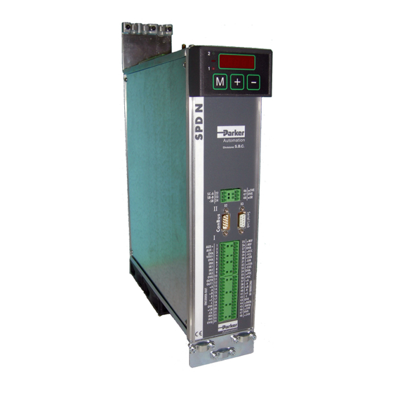
TWIN-N and SPD-N 1.3 Identification The converters of the TWIN-N series are available in 3 models: TWIN 2N, TWIN 5N and TWIN 8N. The number that follows the TWIN-N abbreviation corresponds to the rated current of the converter in amperes. - Page 10 Parker Hannifin S.p.A. Divisione S.B.C. user’s manual TWIN-N and SPD-N An example of this label is given below. Serial number Model Power supply Output voltage Input voltage Output current Output frequency Input frequency Input current The performance of converter is guaranteed only with synchronous motors with permanent magnets MB and SMB Series that have been manufactured by us.
-
Page 11: Safety Instructions
(ratings). In case of doubt contact the Parker Hannifin service centre. • Drives are to be intended as components for use in machine or systems. Therefore they can be... -
Page 12: Safety Instructions For Transportation And Storage
Parker Hannifin S.p.A. Divisione S.B.C. user’s manual TWIN-N and SPD-N 1.4.3 Safety instructions for transportation and storage • The ambient conditions given in the product documentation must be observed for transportation and storage (temperature, humidity, mechanical stress and aggressive atmosphere). -
Page 13: Safety Instructions For Operation
Parker Hannifin S.p.A. Divisione S.B.C. user’s manual TWIN-N and SPD-N 1.4.5 Safety instructions for operation High voltage ! Risk of electric shock ! Danger of life ! • All live parts must be protected against direct contact. The drive must be closed inside a cabinet before switching it on. -
Page 14: Safety Instructions For Maintenance
• It is extremely dangerous to remove covers or part of the external enclosure from the equipment. Risk of personal injury. The warranty immediately decay. • In case of malfunction consult the alarm list described in the user manual or address Parker Hannifin. The drives are not field repairable. -
Page 15: Applicable Standards
Electrolytic capacitor contain electrolyte and printed circuit boards contain lead, both of which are classified as hazardous waste and must be removed and handled according to local regulations. The S.B.C. division of the Parker Hannifin Company, together with local distributors and in accordance with EU standard 2002/96/EC, undertakes to withdraw and... -
Page 16: Warranty
The warranty duration if 1 (one) year. The converter must not be opened, accessed or modified in any of its part. Any attempt to do so would cause the 1-year warranty to be cancelled with immediate effect.. Parker Hannifin declines any responsibility for damages that may be caused by inappropriate use of the converter. -
Page 17: Technical Data
Parker Hannifin S.p.A. Divisione S.B.C. user’s manual TWIN-N and SPD-N 1.5.2 Technical data Model Item Unit TWIN2N TWIN5N TWIN8N SPD2N SPD5N SPD8N SPD16N Power stage Mains frequency 50 - 60 ± 5% 3-phase voltage range 200-10% … 480+10% 1-phase voltage range 200-10% …... - Page 18 Parker Hannifin S.p.A. Divisione S.B.C. user’s manual TWIN-N and SPD-N Digital inputs type Opto coupled number (each single axis) number (shared by the two axe) 2 (IN4,IN5) input impedance kΩ 24 ± 10% Input High voltage range Input Low voltage range 0÷5...
-
Page 19: Main Software Features
Besides having all of the features required by the market of a servo converter, the Parker-S.B.C. drives for brushless motors are also capable of executing “motion” functions that can be used for a large number of applications, without having the typical need of programming an axis control. - Page 20 Parker Hannifin S.p.A. Divisione S.B.C. user’s manual TWIN-N and SPD-N PLC / PC I / O I / O Bridge Drive Drive Drive Drive Drive Drive S.B.C. S.B.C. S.B.C. S.B.C. S.B.C. S.B.C. The group of converters used for an application become a single peripheral unit of the PLC/PC using standard FIELD BUS (Profibus or DeviceNet), and the architecture of the plant control system becomes of the type shown in the figure.
-
Page 21: Mounting
Parker Hannifin S.p.A. Divisione S.B.C. user’s manual TWIN-N and SPD-N 2 MOUNTING • The converter must be mounted vertically with the power block • A space of at least 100 mm. must be left free above and beneath the converter. -
Page 22: Cable Connections And Shielding
Parker Hannifin S.p.A. Divisione S.B.C. user’s manual TWIN-N and SPD-N 2.1.2 Cable connections and shielding With the exception of mains cables to the filter, all power and control cables must be shielded and, wherever possible, kept segregated (minimum distance 20 cm). If control and power cables must cross, the intersection must be at a right angle. - Page 23 Parker Hannifin S.p.A. Divisione S.B.C. user’s manual TWIN-N and SPD-N * The PE bar (for power grounding) must be mounted directly in contact; insulated columns are not to be used. ** The signal cable shields can be connected to a bar (HF) different from the PE bar or connected directly the metallic cable clamps to electrical cabinet back-plate.
-
Page 24: Mains And Motor Side Filters
Parker Hannifin S.p.A. Divisione S.B.C. user’s manual TWIN-N and SPD-N 2.1.4 Mains and motor side filters It is usually necessary to use external filters in addition to internal filters the drive is provided with, on the mains input and sometimes on the motor output. -
Page 25: Signal Connectors Layout
Parker Hannifin S.p.A. Divisione S.B.C. user’s manual TWIN-N and SPD-N 2.2 Signal connectors layout Power terminal connections LINE earth MOTOR I earth U-II MOTOR II (only TWIN-N) V-II W-II +BUS Int-res BUS CONFIGURATION Com-brk -BUS I axis terminal connections Rif. AUX + Rif. - Page 26 Parker Hannifin S.p.A. Divisione S.B.C. user’s manual TWIN-N and SPD-N I axis terminal connections (only TWIN-N) Rif. AUX + Rif. Analog + Rif. AUX - Rif. Analog - 0VA (0V Analog) 0VA (0V Analog) Vout ECC+ 0VA (0V Analog) ECC-...
-
Page 27: Connections
Parker Hannifin S.p.A. Divisione S.B.C. user’s manual TWIN-N and SPD-N 2.3 Connections Power cable specifications Maximum length 35m mobile or fixed installation depending on the applications max. conductor capacity 150pF/m Cross section TWIN-N 2A+2A 5A+5A 8A+8° Power Mains 2 mm... -
Page 28: Ground Connections (Pe)
Parker Hannifin S.p.A. Divisione S.B.C. user’s manual TWIN-N and SPD-N Resolver cable The cable must consist of four individually shielded and insulated twisted pairs protected by a shield. The conductor-conductor capacity for the length used cannot exceed 10 nF and the section cannot be less than 0.22 mm... -
Page 29: Line Connection Diagrams
Parker Hannifin S.p.A. Divisione S.B.C. user’s manual TWIN-N and SPD-N 2.5 Line connection diagrams The converter can be used only in grounded TT and TN industrial networks. Suitable for use on a circuit capable of delivering not more than 5kArms symmetrical amperes at maximum voltage 480V +10%. -
Page 30: Motor Connection Diagrams
Parker Hannifin S.p.A. Divisione S.B.C. user’s manual TWIN-N and SPD-N 2.6 Motor connection diagrams MIL motor connector 2.7 Resolver connection diagrams MIL resolver connector 2.8 Signal cables connection The cable used for the analogue reference must be a shielded twisted pair. The cable used to connect the signals of the simulated encoder must consist of three twisted pairs with a general shield. -
Page 31: Encoder Connection
Parker Hannifin S.p.A. Divisione S.B.C. user’s manual TWIN-N and SPD-N 2.9 Encoder connection The line termination resistors must be connected and the value is 180Ω... -
Page 32: Encoder Sinusoidal + Endat Connection
Parker Hannifin S.p.A. Divisione S.B.C. user’s manual TWIN-N and SPD-N 2.10 Encoder sinusoidal + EnDat connection As far as the cable is concerned, you may use a Heidenhain cable or one with the same features. The cable must not be longer than 20 metres. -
Page 33: Encoder Sinusoidal + Hiperface Connection
Parker Hannifin S.p.A. Divisione S.B.C. user’s manual TWIN-N and SPD-N 2.11 Encoder sinusoidal + Hiperface connection N.B.: the drive requires that the signal Sin+ must be inverted in Sin-, and vice versa; as is showed above. -
Page 34: Incremental Encoder + Hall Sensor
Parker Hannifin S.p.A. Divisione S.B.C. user’s manual TWIN-N and SPD-N 2.12 Incremental encoder + HALL sensor... -
Page 35: Sincos (One Sin Wave Per Pole Pitch)
Parker Hannifin S.p.A. Divisione S.B.C. user’s manual TWIN-N and SPD-N 2.13 SinCos (one sin wave per pole pitch) -
Page 36: Frequecy Input/Output Connection
Parker Hannifin S.p.A. Divisione S.B.C. user’s manual TWIN-N and SPD-N 2.14 Frequecy input/output connection The drive has the possibility to “read” two inputs in frequency. The first input Encoder IN type. The input can receive signals in quadrature and frequency/sign, (b42.5), from an incremental encoder to 5 Volt-DC as from standard LineDrive-RS422. -
Page 37: Connecting The Drive To The Digital-Lock
Parker Hannifin S.p.A. Divisione S.B.C. user’s manual TWIN-N and SPD-N 2.14.1 Connecting the drive to the digital-lock In the example given above, the connection of two drives to the Digital-Lock with a master is shown, but the diagram could be extended to several converters respecting the series connection. The line charge resistors must be connected to the last converter. -
Page 38: Serial Line Connection
Parker Hannifin S.p.A. Divisione S.B.C. user’s manual TWIN-N and SPD-N 2.15 Serial line connection The serial line of the drive can be configured as either RS-422 or as RS-485 depending on how the connection is made. Realize the ending only on the last node, like shown in the following. For the... -
Page 39: Can Line Connection
Parker Hannifin S.p.A. Divisione S.B.C. user’s manual TWIN-N and SPD-N 2.16 CAN line connection There is a CAN-bus interface on the drive, type Physical layer ISO/DIS11898, the DATA link is full CAN version 2.0 part A (ID 11 bit), and a subset used for application layer SBC CAN. Realize the ending only on the last node, like shown in the following 2.17 External +24V power supply for the control stage... -
Page 40: External Braking Resistance
Parker Hannifin S.p.A. Divisione S.B.C. user’s manual TWIN-N and SPD-N 2.18 External braking resistance The drive has an internal braking resistance. When a higher braking power is needed, it is possible to connect an external braking resistance to the drive. -
Page 41: Using The Keyboard
Parker Hannifin S.p.A. Divisione S.B.C. user’s manual TWIN-N and SPD-N 3 Using the keyboard The keyboard-display module is easy to use. It is used to program the functional data, control the status of the converter and send commands. It consists of only three keys located directly beneath the display. - Page 42 Parker Hannifin S.p.A. Divisione S.B.C. user’s manual TWIN-N and SPD-N Hold M pressed for 2 sec. while the name of a parameter (PRxx) is displayed to make the keypad control switch to a different axis; a led will denote the active axis.
-
Page 43: Power Supply Mode
Parker Hannifin S.p.A. Divisione S.B.C. user’s manual TWIN-N and SPD-N 4 POWER SUPPLY MODE 4.1 “Low” voltage power supply This procedure is for those situations in which the operator needs to work in close proximity to the machine in a situation which could be potentially hazardous. In these conditions, the operator must move the axes with a drive power supply voltage lower than the nominal rating (from 40 to 180V~, and from 57 to 255 VDC), so that the maximum allowable speed of the axes is also lowered. -
Page 44: High" Voltage Power Supply
Parker Hannifin S.p.A. Divisione S.B.C. user’s manual TWIN-N and SPD-N 4.2 “High” voltage power supply In “high ” voltage operating mode (b40.0=0), the converter can supplied as follows: AC 3-phase network (200…480 ±10%) Set b39.0=0 (default). The converter can automatically detect the power supply voltage rating and adapts internal operating parameters accordingly. -
Page 45: Start-Up
Parker Hannifin S.p.A. Divisione S.B.C. user’s manual TWIN-N and SPD-N 5 START-UP In Its basic configuration the drive can control both synchronous permanent magnet motors (brushless) and asynchronous induction motors, with feedback. The setting of Pr217 can select either of the following: Pr217=0 synchronous motor (default setting). -
Page 46: Changing Motor Data
Parker Hannifin S.p.A. Divisione S.B.C. user’s manual TWIN-N and SPD-N After setting the parameters that fit the motor, the operator must give the save data command, b99.15. The drive will calculate the correct values of Pr2, Pr3, Pr16, Pr17, Pr18, and Pr19 and save the parameters. -
Page 47: Feedback Configuration
Parker Hannifin S.p.A. Divisione S.B.C. user’s manual TWIN-N and SPD-N 5.4.1 Feedback configuration The following table reassumes all the possible configurations and indicates the relative formulation of the parameters: Type motor configuration N. of pulses Supply Drive code feedback revolution b42.9... -
Page 48: Feedback From Sincos Encoder Or Sincsos + Endat Encoder
Parker Hannifin S.p.A. Divisione S.B.C. user’s manual TWIN-N and SPD-N The selection of power input voltage is only performed at the drive’s start up. In order to enable the selected voltage, save the parameters, then switch off and on again the drive. -
Page 49: Feedback From Incremental Encoder
Parker Hannifin S.p.A. Divisione S.B.C. user’s manual TWIN-N and SPD-N 5.6 Feedback from incremental encoder In place of the resolver it is possible to use an incremental encoder (must be expressly requested when placing your order). When the feedback is incremental encoder see par. “ setting feedback ”. -
Page 50: Type 2 Phasing
Parker Hannifin S.p.A. Divisione S.B.C. user’s manual TWIN-N and SPD-N 5.7.2 Type 2 phasing b94.4 actives this procedure. The parameters are shown in the table below: Type/ Par. Description Field/Unit Notes Pr196 To insert number of the step to turn encoder ±32767... -
Page 51: First Commissioning
Parker Hannifin S.p.A. Divisione S.B.C. user’s manual TWIN-N and SPD-N 5.8 First commissioning The steps to be followed carefully the first time the converter is used are given below. supply the drive with only 24V and insert the motor and feedback data, save (b99.15) and put off the device. -
Page 52: Speed Control Adjustment
Parker Hannifin S.p.A. Divisione S.B.C. user’s manual TWIN-N and SPD-N 5.9 Speed control adjustment SOME IMPORTANT CONCEPTS SPEED LOOP : The main task of a converter is to control motor speed so that it follows as faithfully as possible the speed request that is generally known as the REFERENCE. - Page 53 Parker Hannifin S.p.A. Divisione S.B.C. user’s manual TWIN-N and SPD-N BEFORE BEGINNING Study the diagram below carefully (Fig. 1): Fig. 1 This diagram shows the response of the system to a square wave speed reference. Channel 1 (Ch1) represents the speed and channel 2 (Ch2) the current of the motor. In practice, the probe has been connected to terminal 6 of the X4 (Vout).
- Page 54 Parker Hannifin S.p.A. Divisione S.B.C. user’s manual TWIN-N and SPD-N Fig.2 For increasing values of Pr17, the response of the system will be similar to what is shown in figure 3 below: Fig.3 The optimal value of Pr17 will be attained with a response of the system as shown in figure 4...
- Page 55 Parker Hannifin S.p.A. Divisione S.B.C. user’s manual TWIN-N and SPD-N Fig. 4 An overshoot of about 10% must be obtained. It is important that after the overshoot, an undershoot does not occur. Once the optimal value of Pr17 has been established, we must analyze the movement of the axis.
- Page 56 Parker Hannifin S.p.A. Divisione S.B.C. user’s manual TWIN-N and SPD-N Fig. 6 If mechanical parts are used which very easily tend to enter into oscillation, we recommend you use very low values of Pr16. In this configuration the SLVD_N typically dampens the torque request of the motor in order to avoid triggering mechanical oscillations.
- Page 57 Parker Hannifin S.p.A. Divisione S.B.C. user’s manual TWIN-N and SPD-N ADJUSTMENT WITHOUT USING INSTRUMENTATION If you do not have an oscilloscope, you must: a) Determine the value of Pr16 as described above. b) Determine the Pr17 parameter by using the following formula: ⋅...
-
Page 58: Parameters And Programming
Parker Hannifin S.p.A. Divisione S.B.C. user’s manual TWIN-N and SPD-N 6 PARAMETERS AND PROGRAMMING The torque, speed, acceleration and position control functions are carried out by special digital electronics. In this section we explain how parameters are set and the meaning of each parameter. We also provide the functional block diagram and the description of advanced functions. - Page 59 Parker Hannifin S.p.A. Divisione S.B.C. user’s manual TWIN-N and SPD-N Main parameters Pr0…Pr49, Pr151…Pr167, Pr188…Pr280 Position loop Pr50…Pr70 pico-PLC parameters Pr71…Pr99 Operating mode parameters Pr100…Pr150, Pr168…Pr187 pico-PLC parameters From Pr151 to Pr163 pico-PLC instructions From In0 to In255 The units of measurement and the main resolutions of the parameters are:...
- Page 60 Parker Hannifin S.p.A. Divisione S.B.C. user’s manual TWIN-N and SPD-N • Read/write of the PrX parameter Pr X A = value of the PrX parameter Pr X • Read/write of the PrX parameter B = value that depends on the values of A and PrX •...
-
Page 61: Main Parameters
Parker Hannifin S.p.A. Divisione S.B.C. user’s manual TWIN-N and SPD-N 6.1 Main parameters Legend: R : read; W : write; M : memory; K : key parameter. Par. Descrizione Campo Def. Tipo/ Note Pr 0 Motor speed : a read-only parameter expressed in rpm; the ±... - Page 62 Parker Hannifin S.p.A. Divisione S.B.C. user’s manual TWIN-N and SPD-N Par. Descrizione Campo Def. Tipo/ Note Pr 9 Deceleration ramp for positive speed: Positive speed 0.002÷ 0.002 deceleration required by the motor via the speed reference is 65.535 internally limited so that to achieve an acceleration of 1000 [s/krpm] rpm, Pr9 seconds are necessary.
- Page 63 Parker Hannifin S.p.A. Divisione S.B.C. user’s manual TWIN-N and SPD-N Par. Descrizione Campo Def. Tipo/ Note Pr 23 Alarm code: This is the code for the alarm that is present. 0÷255 Code 0 represents the absence of alarms. Consult the table of alarm codes for more details.
- Page 64 Parker Hannifin S.p.A. Divisione S.B.C. user’s manual TWIN-N and SPD-N Par. Descrizione Campo Def. Tipo/ Note Pr 43 Zero encoder offset . This parameter is used to modify the 0÷4095 position of the output zero trace for the zero resolver (Pr28).
- Page 65 Parker Hannifin S.p.A. Divisione S.B.C. user’s manual TWIN-N and SPD-N Par. Descrizione Campo Def. Tipo/ Note Pr207 Overvoltage limit. If b39.1=1, overvoltage and braking -32767÷ alarm. This value decides the braking limit and the +32767 overvoltage alarm. It’s important to know well the characteristics of the drive before setting this value for avoid serious damages to the drive.
-
Page 66: Binary Parameters
Parker Hannifin S.p.A. Divisione S.B.C. user’s manual TWIN-N and SPD-N 6.2 Binary parameters Par. Description Def. Field b39.0 Undervoltage in continuous current. b39.0=1 When the drive is supplied in continuous voltage, this bit permits the control of the undervoltage alarm. - Page 67 Parker Hannifin S.p.A. Divisione S.B.C. user’s manual TWIN-N and SPD-N Par. Description Def. Field b40.11 Injection of third harmonic in modulation. b40.12 Selection of the digital/analogue reference: If = 0, the analogue input will be selected as the main reference. If = 1, the reference will be digital and b40.13 can be used to select parameter Pr4 or...
- Page 68 Parker Hannifin S.p.A. Divisione S.B.C. user’s manual TWIN-N and SPD-N Par. Description Def. Field b42.3 Reinitializing the serial line and the SBCCAN. Command to initialise serial communication whenever the speed value of the serial line (Pr26) has been modified. Command to initialise the SBCCAN whenever the address or the function mode has been modified.
- Page 69 Parker Hannifin S.p.A. Divisione S.B.C. user’s manual TWIN-N and SPD-N Par. Description Def. Field b99.10 Command to reset alarms. This command sets Pr23 and Pr24 to 0. If the alarm continues, it is displayed on the screen. This command cannot be used if there is a check-sum error (Pr23 = 10, 11).
- Page 70 Parker Hannifin S.p.A. Divisione S.B.C. user’s manual TWIN-N and SPD-N Left limit 40.4 Analogue reference offset Right limit 40.5 Analogue reference Main analogue input Pr45 Stop 40.6 input Reference offset Main reference Accel and decel Stop ramp Full scale ref 1...
-
Page 71: Operating Modes
Parker Hannifin S.p.A. Divisione S.B.C. user’s manual TWIN-N and SPD-N 7 Operating modes Parameter Pr31 (default = 0) is used to select the operating mode. Every operating mode controls speed using parameter Pr6 and can use parameter PR21 to limit the torque at the motor (see the block diagram). -
Page 72: Position Control
Parker Hannifin S.p.A. Divisione S.B.C. user’s manual TWIN-N and SPD-N 7.1 Position control All operating modes need to control the motor in position by using the position loop described in the block diagram shown in the figure below. Pr106 Reference speed... - Page 73 Parker Hannifin S.p.A. Divisione S.B.C. user’s manual TWIN-N and SPD-N Par. Description field/Unit Def. Type /Note Pr50 Maximum speed . This parameter limits the 0÷9000 3000 maximum speed of the motor. It can be useful to limit the speed during a sudden link or during a [rpm] quick change of speed.
- Page 74 Parker Hannifin S.p.A. Divisione S.B.C. user’s manual TWIN-N and SPD-N Par. Description field/Unit Def. Type /Note Pr212 -32000÷ F/Dir reference multiplier. Using this parameter +32000 and Pr213, the user can set the ratio desired for the input reference frequency. Pr213 F/Dir reference divider.
-
Page 75: Torque Control (Operating Mode 1)
Parker Hannifin S.p.A. Divisione S.B.C. user’s manual TWIN-N and SPD-N 7.2 Torque control (operating mode 1) This operating mode does not control the torque in the classic way since the speed control continues to work to control the speed limit. The torque reference will be the Pr7 main reference. -
Page 76: Digital Lock + Positioner (Operating Mode 13)
Parker Hannifin S.p.A. Divisione S.B.C. user’s manual TWIN-N and SPD-N 7.3 Digital Lock + Positioner (operating mode 13) Operating mode 13 includes the Digital Lock, dynamic positioner and flow speed functions in order to use them at the same time. The tracking function refers to the input frequency signal (X3 connector) set as an input encoder signal by setting b42.0 = 0, b42.1 =1, and b42.5 = 1. - Page 77 Parker Hannifin S.p.A. Divisione S.B.C. user’s manual TWIN-N and SPD-N b231.10=1 TAB0 activation by profiles TAB0 point Positioner variables Pointer to table Pr193 Pr108 Speed Pr109 Accel/Decel. ramp. Pr118 Final position Pr119 Pr108 Speed Pr109 Accel/Decel. ramp. Pr118 Final position...
- Page 78 Parker Hannifin S.p.A. Divisione S.B.C. user’s manual TWIN-N and SPD-N Par. Description Field/Unit Def. Type/Note Actual position (electrical shaft) . Indicates the Pr114 [count] actual position with reference to the electrical Pr115 shaft. Pr116 Actual position (positioner) . Indicates the actual...
- Page 79 Parker Hannifin S.p.A. Divisione S.B.C. user’s manual TWIN-N and SPD-N OPM13 In progress b150.0 Pr108 Speed Acceleration Target position Pr109 Reset 1 b150.10 Pr61:60 Ref.Position=Motor ref.=0 Profile direction b150.4 Posizione attuale Actual position Reset 2 b150.11 Ref.Position=Motor ref. Pr117:116 Pr115:114 Velocità...
-
Page 80: Electronic Cam (Operating Mode 14)
Parker Hannifin S.p.A. Divisione S.B.C. user’s manual TWIN-N and SPD-N 7.4 Electronic cam (operating mode 14) Operating mode 14 is expressly designed to meet the needs of packaging machines that require electronic cams. This program is in the drive’s basic configuration and it can be programmed by selecting Pr31=14 and b99.11=1, parameters to select the operating mode and... -
Page 81: Speed Mode
Parker Hannifin S.p.A. Divisione S.B.C. user’s manual TWIN-N and SPD-N 7.4.2 Speed mode It actives with Pr102=3 and the parameters are Pr100, speed, and Pr101, acceleration and deceleration ramp. 7.4.3 Electronic cam Four tables are available, namely TAB0, TAB1, TAB2 and TAB3, that have been implemented to perform a series of cam functions. - Page 82 Parker Hannifin S.p.A. Divisione S.B.C. user’s manual TWIN-N and SPD-N r a m p a a g g a n c i o Pr102=9 Tab1 Engage ramp r a m p a s g a n c i o Pr102=10...
- Page 83 Parker Hannifin S.p.A. Divisione S.B.C. user’s manual TWIN-N and SPD-N b150.12 and b150.13 command the engage and the disengage in correspondence of the master phases written in Pr127:126 and in Pr 129:128, they are always referred to master module of CAM1.
- Page 84 Parker Hannifin S.p.A. Divisione S.B.C. user’s manual TWIN-N and SPD-N Pr126:127 Master axis phase for engaging. Unit = steps; range 0..2 Default=0. If b150.12 = 1, when the position of the master Pr112:113 exceeds Pr126:127, Pr102 is brought to position 2 and b150.12 returns to 0 to indicate that engaging has been achieved.
- Page 85 Parker Hannifin S.p.A. Divisione S.B.C. user’s manual TWIN-N and SPD-N 0 when the command has been enabled. Immediate electronic cam engaging. Command to engage the cam movement. b150.14 This bit is automatically set to 0 when the command has been enabled.
- Page 86 Parker Hannifin S.p.A Divisione S.B.C. user’s manual TWIN-N and SPD-N Positioning OPM14 Speed Change of the value slave axis Acceleration Pr108 module in phase Pr185:184 Pr109 b181.12 Target position Pr119:118 Pr169:168 Select CAM1 table Position slave No source b180.0 Pr135:134...
-
Page 87: Opm 14 Linear Engage Cam
Parker Hannifin S.p.A Divisione S.B.C. user’s manual TWIN-N and SPD-N 7.4.4 OPM 14 Linear engage CAM With OPM14 exists the possibility to program a linear engage cam on master module. It’s necessary to define the space to use of the module master in which executing the engage cam of the slave. - Page 88 Parker Hannifin S.p.A Divisione S.B.C. user’s manual TWIN-N and SPD-N Cam table engage automatic b150.12=1 (autoset after engage and autoreset after engage to the drive’s TAB) Master Module Pr110:111=30000 Step/Motor Slave Module Pr114:115 = 10000 Step/Motor space covered in engage from slave...
-
Page 89: Electronic Cam (Op. Mod. 11)
Parker Hannifin S.p.A Divisione S.B.C. user’s manual TWIN-N and SPD-N 7.5 Electronic cam (op. mod. 11) Operating mode 11 is expressly designed to meet the needs of packaging machines that require 2 electronic cams. This program is in the drive’s basic configuration and it can be programmed by selecting Pr31=14 and b99.11=1, parameters to select the operating mode and... -
Page 90: Positionator
Parker Hannifin S.p.A Divisione S.B.C. user’s manual TWIN-N and SPD-N 7.5.1 Positionator This is a trapezoidal profile generator, with the following user-definable parameters: speed profile acceleration and deceleration ramp value target position in motor step The parameter referred to the target position is absolute. The difference between the target position and the reference position, generates the direction of the movement. - Page 91 Parker Hannifin S.p.A Divisione S.B.C. user’s manual TWIN-N and SPD-N Predetermined function Table y = x - s e n x Pr102=5 Pr102=6 Function y=x Function y=x-senx Tab0 y=senx p r o f i l o t r i a n g o l a r e...
- Page 92 Parker Hannifin S.p.A Divisione S.B.C. user’s manual TWIN-N and SPD-N engage/disengage of the CAM1, it allows an engage/disengage immediate of the same without to consider the master phase. Modules with negative sign cannot be set in CAM1. CAM2 will be engaged and disengaged only by command and always when the master is in phase 0, or by a single execution command (Single Shoot).
- Page 93 Parker Hannifin S.p.A Divisione S.B.C. user’s manual TWIN-N and SPD-N Example 1 Speed profile axis slave without cam scale 3000 Scale CAM1: Profilo risultante 2500 Pr115:114=10000 module Pr177:176=00 start point 2000 Pr179:178=10000 execution space 1500 Scale CAM2: CAM1 1000 Pr185:184=10000 module...
-
Page 94: Automatic Activation Of Cam Tables
Parker Hannifin S.p.A Divisione S.B.C. user’s manual TWIN-N and SPD-N 7.5.2.1 Automatic activation of CAM tables Beside enabling tables on programmable master phase or by immediate command as shown above, the drive offers a default function providing for an automatic sequence to enable the tables in order to concur some functionalities like engage and disengage cam, with connection tables. - Page 95 Parker Hannifin S.p.A Divisione S.B.C. user’s manual TWIN-N and SPD-N b181.14 Disengage comand b181.13 Engage comand Pr105 Pr105 Sector Sector disengage engage ramp ramp Tab 3 Tab 1 Tab 0 Tab 2 Tab 3 360° 360° 360° 360° 0° Master module...
- Page 96 Parker Hannifin S.p.A Divisione S.B.C. user’s manual TWIN-N and SPD-N Decimal parameters Pr101:100 Reference module position ( addition as module of POS+CAM1+CAM2). Default=0. Pr102 Function selector. The value indicates one predetermined function ( see the predetermined function table). Once that the command has been given, the table comes generated with the selected function.
- Page 97 Parker Hannifin S.p.A Divisione S.B.C. user’s manual TWIN-N and SPD-N Pr154 Multiplicative factor of reference ENCODER CAN. Pr155 Divisor factor of reference ENCODER CAN Pr157:156 Encoder CAN counter . . Pr158 Encoder CAN pointer (b70.10). Pr169:168 Master phase for engaging of the Tab.0 (b180.0). When the master phase matches the programmed value, then the slave engages to the master.
- Page 98 Parker Hannifin S.p.A Divisione S.B.C. user’s manual TWIN-N and SPD-N b180.1 Start Tab.1 on master phase of Pr170:171. =1 enables Tab0 at the master phase declared in Pr171:170. The parameter values to start on master phase must be between 0 and Pr111:110 master module.
- Page 99 Parker Hannifin S.p.A Divisione S.B.C. user’s manual TWIN-N and SPD-N b181.9 Enable counter position from CAM1 to global counter(Pr130:131). This command, b181.9=1, enable the reference of CAM1. This value is added algebraically to global counter of reference. b181.10 Enable counter position from CAM 2 to global counter(Pr130:131). This command, b181.9=1, enable the reference of positioner.
- Page 100 Parker Hannifin S.p.A Divisione S.B.C. user’s manual TWIN-N and SPD-N Positioning OPM11 Speed Acceleration Pr108 Pr109 Target position Pr119:118 Master position Master axe b180.0 Reference position offset TAB0 module position Pr117:116 Master axe Master axe b180.4 Pr169:168 Pr101:100 b150.3 position...
-
Page 101: Position Control Through The Canbus (Operating Mode 15)
Parker Hannifin S.p.A Divisione S.B.C. user’s manual TWIN-N and SPD-N 7.6 Position control through the CANbus (operating mode 15) If the operating mode 15 is enabled, the drive will execute a Position loop of proportional type with feed-forward, the profile generator is regarded as external and it will send the information regarding the position and speed reference via CAN bus, according to the SBCCAN protocol (see chapter CAN bus). - Page 102 Parker Hannifin S.p.A Divisione S.B.C. user’s manual TWIN-N and SPD-N Par. Description Type/ Notes Feedback transmission enable . If = 1, when the type 0 b150.2 SYNC is received, Pr116:117 will be transmitted via the CAN bus. Reply status. In the cyclic reply message, if b150.3=0 the b150.3...
- Page 103 Parker Hannifin S.p.A Divisione S.B.C. user’s manual TWIN-N and SPD-N opm 15 for Twin drive Pr105 Pr104 feedforward speed feedforward speed from CanBus Pb150.10 target position = motor position = 0 reset 1 Pb150.2 enable auto-answer sync 0 Pb150.4 Pr 115:114...
-
Page 104: Basic Functions
Parker Hannifin S.p.A Divisione S.B.C. user’s manual TWIN-N and SPD-N 7.7 Basic functions The standard drive functions include protection functions whose parameters can be set, such as automatic limitations of current delivered based on the estimated dissipation (thermal image or i t drive and motor);... -
Page 105: Speed Adjustment
Parker Hannifin S.p.A Divisione S.B.C. user’s manual TWIN-N and SPD-N 7.7.2 Speed adjustment In the operating mode default conditions (Pr31=0), the drive adjusts the motor in speed based on the reference value. The reference origin can be selected with the main block parameters, between analogue (external potentiometer), internal (digital), or external pulse string. -
Page 106: Value Comparators
Parker Hannifin S.p.A Divisione S.B.C. user’s manual TWIN-N and SPD-N With the “Virtual encoder” function enabled, a virtual encoder (dummy Master) will be available, whose speed will be that set in Pr3. The set speed has a resolution equal to 1 rpm, the limit is the maximum frequency (see the technical data). -
Page 107: Analogue Output Programmable
Parker Hannifin S.p.A Divisione S.B.C. user’s manual TWIN-N and SPD-N 7.7.8 Analogue output programmable In terminal block is available one analogue output programmable (pin: 4 V e 5 0VA). The parameter Pr188 defines the parameter to monitor. The analogue output scale has a range from –512 to +512 counts corresponding ±10V. -
Page 108: Encoder Can
Parker Hannifin S.p.A Divisione S.B.C. user’s manual TWIN-N and SPD-N Master Pr54 speed encoder Reference multiplier Counter encoder encoder IN Encoder Pr52 input Pr67:66 Pr53 b42.5 b70.9 Reference divider encoder IN Master speed reference CAN multiplier Pr159 Master reference Pr154... - Page 109 Parker Hannifin S.p.A Divisione S.B.C. user’s manual TWIN-N and SPD-N The encoder CAN is active in input and accepts the CAN signal with address setting into Pr202. The output encoder CAN is enable if b42.1=0 and it generates a encoder signal with the same address to CAN node.
-
Page 110: Programming Digital Inputs/Outputs
Parker Hannifin S.p.A Divisione S.B.C. user’s manual TWIN-N and SPD-N 8 Programming digital inputs/outputs 8.1 The pico-PLC The internal pico-PLC is used to connect the external world (inputs/outputs) with the world of the parameters of the drive. The PLC can be used to copy digital input to a binary parameter, to copy a binary parameter to a digital output and to execute mathematical and Boolean operations. - Page 111 Parker Hannifin S.p.A Divisione S.B.C. user’s manual TWIN-N and SPD-N Parametri bit del pico-PLC Par. Description Def. Type Note b90.0 Status of digital input 0 . Status of digital input 0. b90.1 Status of digital input 1 . Status of digital input 1 b90.2...
- Page 112 Parker Hannifin S.p.A Divisione S.B.C. user’s manual TWIN-N and SPD-N PLC INSTRUCTIONS Pa.y Pa.y loads the y bit of the Pa parameter on the stack Pa.y Pa,y loads the negated y bit of the Pa parameter on the stack Pa.y...
- Page 113 Parker Hannifin S.p.A Divisione S.B.C. user’s manual TWIN-N and SPD-N FUNCTIONAL DESCRIPTION The Pico-PLC program is scanned every 6.144 milliseconds. Based on this sampling, the inputs are first read, then the two timers (Pr92 Pr93 b999.0 and b99.1) are updated, the user program is scanned and finally outputs are updated.
- Page 114 Parker Hannifin S.p.A Divisione S.B.C. user’s manual TWIN-N and SPD-N In the mathematical operations on double words, the operands and the result are defined as follows: the parameter of the operand defines the least significant part while the most significant part is represented by the next word.
-
Page 115: Programming With Motionwiz
Parker Hannifin S.p.A Divisione S.B.C. user’s manual TWIN-N and SPD-N 8.2 Programming with MotionWiz The serial kit is supplied to enable communication between a PC and the drive. The kit includes an RS-422/RS-232 converter, relative 230V~ power supply and serial connection cable. -
Page 116: Motionwiz
Parker Hannifin S.p.A Divisione S.B.C. user’s manual TWIN-N and SPD-N 8.3 MotionWiz The configuration tool is called “MOTIONWIZ” and is used to program the drive while controlling the whole system in real time. PLC programs can also be edited and new files can be generated. -
Page 117: Serial Interface
Parker Hannifin S.p.A Divisione S.B.C. user’s manual TWIN-N and SPD-N 9 SERIAL INTERFACE The serial communication of the converter is half-duplex, master-slave, using an asynchronous RS-485/RS-422 line. The converters take control of the line only if interrogated by the master. - Page 118 Parker Hannifin S.p.A Divisione S.B.C. user’s manual TWIN-N and SPD-N converter response reading a pico-PLC instruction writing a pico-PLC instruction reading a parameter writing a parameter bit modification writing a parameter to all the slaves [BK+LUN] = the LUN field (first 3 bits) indicates the number of bytes of the data transmitted (a parameter or a PLC instruction);...
- Page 119 Parker Hannifin S.p.A Divisione S.B.C. user’s manual TWIN-N and SPD-N [STX] [101+ADDR] [BK+LUN] [PAR] [D0]... [Dn] [CHK] [CMD6] = is the change bit message of a byte parameter. The message has the following format: [STX] [110+ADDR] [BK+LUN] [PAR] [D0] [D1] [CHK] In this case LUN=2 or else two bytes are sent for the data.
- Page 120 Parker Hannifin S.p.A Divisione S.B.C. user’s manual TWIN-N and SPD-N Instruction Code Length (bytes) Pa.y Pa.y Pa.y OUTN Pa.y Pa.y ANDN Pa.y Pa.y Pa.y Pa, Pb, Pc Pa, Pb, Pc Pa, Pb, Pc Pa, Pb, Pc Pa.y Pa.y FIN b40.y/b150.y The first 4 bits (b0..b3) of the first byte in each instruction contain the instruction code.
- Page 121 Parker Hannifin S.p.A Divisione S.B.C. user’s manual TWIN-N and SPD-N The converter responds with the message: [$7E][$20][$01][$32][$2B][$7E][$00] Second example: reading a 2 byte parameter Suppose we want to read the reference speed (Pr7) and that its value is 2000. Suppose also that the converter has the serial address 1.
-
Page 122: Can Bus Interface
Parker Hannifin S.p.A Divisione S.B.C. user’s manual TWIN-N and SPD-N 10 CAN bus interface A CAN bus interface based on the physical layer ISO/DIS11898 is included on the converter. The Data link layer is the full CAN version 2.0 part A (ID 11 bit) and a subset of the application layer SBCCAN is used. -
Page 123: Description Of The Fields In Real Time Mode
Parker Hannifin S.p.A Divisione S.B.C. user’s manual TWIN-N and SPD-N 10.1.1 Description of the fields in real time mode Cyclic message from the master to the DRIVE Cyclic data Data length 8/6/4 bytes Position Reference Speed Reference Command Field Name... - Page 124 Parker Hannifin S.p.A Divisione S.B.C. user’s manual TWIN-N and SPD-N Cyclic message from the drive to the master Cyclic reply Data length 6/7 byte Field Name Address Motor Position Status Pr27+1 (8bit) Pr116:117 (32 bit) Pr103 Data Identifier ID2 ID1 ID0...
- Page 125 Parker Hannifin S.p.A Divisione S.B.C. user’s manual TWIN-N and SPD-N MultiSynchronism message from the master to the drive MultiSynchronism message Data length 1,2,3,4 byte Field Name Command 0 Command 1 Command 2 Command 3 Pr102 (8bit) Pr102 (8bit) Pr102 (8bit)
-
Page 126: Sub-Field Cmd [0
Parker Hannifin S.p.A Divisione S.B.C. user’s manual TWIN-N and SPD-N Acyclic data write message or parameter request from the master to the drive Acyclic data write or request Data length 7 byte Field Name Cmd & Len Data Address Data... - Page 127 Parker Hannifin S.p.A Divisione S.B.C. user’s manual TWIN-N and SPD-N Broadcast write parameter message from the master to the drive Broadcast data write Data length 7 bytes Field Name Cmd & Len Data Address Data Contents 5 bit command and 3 bit length...
- Page 128 Parker Hannifin S.p.A Divisione S.B.C. user’s manual TWIN-N and SPD-N To evaluate the minimum sampling time, use the following formula: = ( Nr + Nt + 5 ) * 0.12 where: is the minimum sampling time in milliseconds Nr is the number of...
- Page 129 Parker Hannifin S.p.A Divisione S.B.C. user’s manual TWIN-N and SPD-N SBCCAN Feedback from drive1 Feedback from drive2 Feedback from drive3 Feedback from drive4 T X reference Sync RX Feedback Change Pr of drive X Tx reference >400µs cyclic msg to drive1...
-
Page 130: Description Of The Fields In Communication Mode
Parker Hannifin S.p.A. Divisione S.B.C. user’s manual TWIN-N and SPD-N 10.1.2 Description of the fields in communication mode Write or parameter request message from the master to the drive data write or request Data length 7 bytes Field Name Cmd & Len... -
Page 131: Addr & Spare
Parker Hannifin S.p.A. Divisione S.B.C. user’s manual TWIN-N and SPD-N Response to a parameter request message from the drive to the master Data reply Data length 5 byte Field Name Addr & Spare Data Contents Pr27+1 (8bit) 32 bit reply data... -
Page 132: Description Of The Fields Extended Message Set # 2
Parker Hannifin S.p.A. Divisione S.B.C. user’s manual TWIN-N and SPD-N Alarm message from the drive to the master Error Data length 3 bytes Field Name Addr Error Contents Pr27+1 Pr23 Identifier ID2 ID1 ID0 ID10 ID9 ID8 ID7 ID6 ID5 ID4 A0:A4 drive slave address (Pr27+1), valid values 1..31. - Page 133 Parker Hannifin S.p.A. Divisione S.B.C. user’s manual TWIN-N and SPD-N Synchronism message from the master to the drive Block sync Data length 0 bytes Field Name Contents No data Identifier ID2 ID1 ID0 ID10 ID9 ID8 ID7 ID6 Data received are stored from Pr80 to Pr83, and drive sends parameters from Pr84 to Pr87 by...
-
Page 134: Canopen (C Version)
Parker Hannifin S.p.A. Divisione S.B.C. user’s manual TWIN-N and SPD-N 10.2 CANopen (C version) The CANbus node must be set through Pr49 with values from 1 to 127. Transmission speed depends on Pr31, Pr48 e b150.4 as the following table:... -
Page 135: Identifier Id2 Id1 Id0 - - A2 A1 A0
Parker Hannifin S.p.A. Divisione S.B.C. user’s manual TWIN-N and SPD-N Emergency message from Drive to master Emergency message 8 byte Data length Field Name Error code Err. Reg Drive address Data Contents 16 bit code 8 bit error 8 bit address... - Page 136 Parker Hannifin S.p.A. Divisione S.B.C. user’s manual TWIN-N and SPD-N The target position reached message is generated when the motor, after the target position is changed (in operating mode 13 b150.0=1, in operating mode 14 Pr102 not zero), will go to the target position at less than a tolerance set in Pr55 for at least a time of Pr88*2.048msec.
- Page 137 Parker Hannifin S.p.A. Divisione S.B.C. user’s manual TWIN-N and SPD-N If the number of bytes written is greater than two, the operation will also change the parameter Pr81. Read Pr60 from the drive: You will need to read the object by SDO with index-sub_index 0x2000-0x3d (60+1). The value returned will have a length of 4 bytes, the most significant of which will contain Pr61.
- Page 138 Parker Hannifin S.p.A. Divisione S.B.C. user’s manual TWIN-N and SPD-N For pico-PLC writing, it will contain the operating code of the instruction (see Serial interface ). Data Address This field is the address of the parameter involved in the operation (parameter number * 2).
- Page 139 Parker Hannifin S.p.A. Divisione S.B.C. user’s manual TWIN-N and SPD-N A0:A6 Slave drive address (Pr49), valid values 1..127. The bytes of the message are written to the corresponding parameters only if the function described is enabled by setting bit b99.5 to 1, and is done immediately prior to the next pico- PLC scan cycle (every 6.144 msec) from the reception of the PDO4 rx message.
- Page 140 Parker Hannifin S.p.A. Divisione S.B.C. user’s manual TWIN-N and SPD-N PDO1 (tx/rx) object : Realtime Mode (Pr31 = 15): In the same way as for the SBCCAN protocol, a real-time mode has been implemented (operating mode 15) which, for CANopen networks, uses PDO1 (rx/tx) for cyclical data exchange and the SYNC message for synchronizing the position loops.
- Page 141 Parker Hannifin S.p.A. Divisione S.B.C. user’s manual TWIN-N and SPD-N See the next table: DESCRIPTION CANopen user emgy message CANopen user emgy message CANopen user emgy message b39.14 CANopen Node Guard watchdog.
-
Page 142: Canopen Dsp402 (D Version)
Parker Hannifin S.p.A. Divisione S.B.C. user’s manual TWIN-N and SPD-N 10.3 CANopen dsp402 (D version) The CANbus node must be set through Pr49 with values from 1 to 127. Transmission speed depends on Pr31, Pr48 e b150.4 as the following table:... -
Page 143: Dictionary Object Summary Of Ds301 In Drive
Parker Hannifin S.p.A. Divisione S.B.C. user’s manual TWIN-N and SPD-N Life guarding protocol is implemented and can be activated writing life time factor and guard time besides a missing guarding event ,life guarding protocol can be triggered by a missing sync (if b271.8=1) or a bus-off condition. -
Page 144: Dictionary Object Summary Of Dsp402 In Drive
Parker Hannifin S.p.A. Divisione S.B.C. user’s manual TWIN-N and SPD-N [0x200a] : CAM 2 table first 254 points read write access [0x200b] : CAM 2 table first last 3 points read write access [0x200c] : CAM 3 table first 254 points read write access... - Page 145 [0x60c1][3] 'Interpolation data record': INTEGER32 interpolator velocity reference in RPM [0x6502] 'Supported drive modes': see (see 0x6060) [0x6504] 'Drive Manufacturer': "Parker Hannifin div. SBC Italy" [0x6505] 'http drive catalog address': "*** http://www.sbcelettronica.com *** http://www.parker-eme.com ***" Following modes of operation of dsp 402 are implemented beside the device control state...
- Page 146 Parker Hannifin S.p.A. Divisione S.B.C. user’s manual TWIN-N and SPD-N Device Control state machine Homing mode Device Profile 402 Motor CAN node Profile Position mode Interpolated Position mode Here by the schematic of device control with controlword e statusword Control word...
-
Page 147: Object 6040H: Controlword
Parker Hannifin S.p.A. Divisione S.B.C. user’s manual TWIN-N and SPD-N Power disable Fault Fault reaction start active Not ready to Fault switch On Switch On disabled Ready to Switch On Power enable Switched On Operation enable Quick stop active If I t current clamping is active bit 11 of the statusword rises. - Page 148 Parker Hannifin S.p.A. Divisione S.B.C. user’s manual TWIN-N and SPD-N OBJECT DESCRIPTION INDEX 6040h Name Controlword Object Code VAR Data Type UNSIGNED16 Category Mandatory ENTRY DESCRIPTION Access PDO Mapping Possible Value Range UNSIGNED16 Default Value DATA DESCRIPTION The bits of the controlword are defined as follows:...
-
Page 149: Object 6041H: Statusword
Parker Hannifin S.p.A. Divisione S.B.C. user’s manual TWIN-N and SPD-N BITS 4, 5, 6 AND 8: These bits are operation mode specific. The description is situated in the chapter of the special mode. The following table gives an overview: Operation mode... - Page 150 Parker Hannifin S.p.A. Divisione S.B.C. user’s manual TWIN-N and SPD-N Description M /O Ready to switch on Switched on Operation enabled Fault Voltage enabled Quick stop Switch on disabled Warning Manufacturer specific Remote Target reached Internal limit active 12 - 13 Operation mode specific O 14 - 15 Manufacturer specific BITS 0 –...
-
Page 151: Object 605Bh: Shutdown Option Code
Parker Hannifin S.p.A. Divisione S.B.C. user’s manual TWIN-N and SPD-N BIT 8: This bit may be used by a drive manufacturer to implement any manufacturer specific functionality. BIT 9: REMOTE If bit 9 is set, then parameters may be modified via the CAN-network, and the drive executes the content of a command message. -
Page 152: Object 605Ch: Disable Operation Option Code
Parker Hannifin S.p.A. Divisione S.B.C. user’s manual TWIN-N and SPD-N OBJECT DESCRIPTION INDEX 605Bh Name Shutdown option code Object Code Data Type INTEGER16 Category Optional ENTRY DESCRIPTION Access PDO Mapping No Value Range INTEGER16 Default Value DATA DESCRIPTION Value Description -32768 ... -
Page 153: Object 605Ah: Quick Stop Option Code
Parker Hannifin S.p.A. Divisione S.B.C. user’s manual TWIN-N and SPD-N 10.3.2.5 Object 605A : Quick stop option code The parameter quick stop option code determines what action should be taken if the Quick Stop Function is executed. OBJECT DESCRIPTION ENTRY DESCRIPTION... -
Page 154: Object 6060H: Modes Of Operation
Parker Hannifin S.p.A. Divisione S.B.C. user’s manual TWIN-N and SPD-N DATA DESCRIPTION Value Description -32768 ... -1 manufacturer Specific disable drive, motor is free to rotate slow down on slow down ramp slow down on quick stop ramp 10.3.2.7 Object 6060 : Modes of operation The parameter modes of operation switches the actually choosen operation mode. -
Page 155: Functional Description
Parker Hannifin S.p.A. Divisione S.B.C. user’s manual TWIN-N and SPD-N OBJECT DESCRIPTION INDEX 6061h Name Modes of operation display Object Code VAR Data Type INTEGER8 Category Mandatory ENTRY DESCRIPTION Access PDO Mapping Possible Value Range INTEGER8 Default Value DATA DESCRIPTION Same as for object 6060 modes of operation . -
Page 156: Homing Mode (Operative Mode 200)
Parker Hannifin S.p.A. Divisione S.B.C. user’s manual TWIN-N and SPD-N 10.3.4 Homing mode (operative mode 200) In homing mode (Pr31=200) all the standard methods are available the index is referred to the feedback C encoder input track Z, it is also possible to refer the index to the absolute (in the shaft revolution) position of zero of the position feedback (resolver, SinCos absolute etc) setting the homing method to the same absolute value as for track Z indexing but negative .In... -
Page 157: Output Data Description
Parker Hannifin S.p.A. Divisione S.B.C. user’s manual TWIN-N and SPD-N There are two homing speeds ; in a typical cycle the faster speed is used to find the home switch and the slower speed is used to find the index pulse. The manufacturer is allowed some discretion in the use of these speeds as the response to the signals may be dependent upon the hardware used. -
Page 158: Object Dictionary Entries
Parker Hannifin S.p.A. Divisione S.B.C. user’s manual TWIN-N and SPD-N 10.3.6 Object dictionary entries 10.3.6.1 Objects defined in this chapter Index Object Name Type Attr. M/O 607Ch VAR Home offset INTEGER32 6098h Homing method INTEGER8 6099h ARRAY Homing speeds UNSIGNED32 rw... -
Page 159: Object 6098H: Homing Method
Parker Hannifin S.p.A. Divisione S.B.C. user’s manual TWIN-N and SPD-N ENTRY DESCRIPTION Access PDO Mapping Possible Value Range INTEGER32 Default Value 10.3.7.2 Object 6098 : Homing method The homing method object determines the method that will be used during homing. OBJECT... -
Page 160: Object 609Ah: Homing Acceleration
Parker Hannifin S.p.A. Divisione S.B.C. user’s manual TWIN-N and SPD-N ENTRY DESCRIPTION Sub-Index Description number of entries Entry Category Mandatory Access PDO Mapping Value Range Default Value Sub-Index Description Speed during search for switch Entry Category Mandatory Access PDO Mapping... -
Page 161: Functional Description
Parker Hannifin S.p.A. Divisione S.B.C. user’s manual TWIN-N and SPD-N 10.3.8 Functional description By choosing a method of homing by writing a value to homing method will clearly establish the homing signal (positive limit switch, negative limit switch, home switch) the direction of actuation and where appropriate the position of the index pulse(*). -
Page 162: Method 2: Homing On The Positive Limit Switch And Index Pulse
Parker Hannifin S.p.A. Divisione S.B.C. user’s manual TWIN-N and SPD-N Homing on the negative limit switch and index pulse 10.3.8.1.2 Method 2: Homing on the positive limit switch and index pulse Using this method the initial direction of movement is rightward if the positive limit switch is inactive (here shown as low). -
Page 163: Methods 5 And 6: Homing On The Negative Home Switch And Index Pul
Parker Hannifin S.p.A. Divisione S.B.C. user’s manual TWIN-N and SPD-N 10.3.8.1.4 Methods 5 and 6: Homing on the negative home switch and index pul. Using methods 5 or 6 the initial direction of movement is dependent on the state of the home switch. -
Page 164: Methods 15 And 16: Reserved
Parker Hannifin S.p.A. Divisione S.B.C. user’s manual TWIN-N and SPD-N (10) (10) (10) Index pulse Home switch Positive limit switch Figure 26: Homing on the home switch and index pulse - positive initial move (14) (12) (13) (11) (14) (11) -
Page 165: Methods 17 To 30: Homing Without An Index Pulse
Parker Hannifin S.p.A. Divisione S.B.C. user’s manual TWIN-N and SPD-N 10.3.8.1.7 Methods 17 to 30: Homing without an index pulse These methods are similar to methods 1 to 14 except that the home position is not dependent on the index pulse but only dependent on the relevant home or limit switch transitions. For example methods 19 and 20 are similar to methods 3 and 4 as shown in the following diagram. -
Page 166: Profile Position Mode (Operative Mode 201)
Parker Hannifin S.p.A. Divisione S.B.C. user’s manual TWIN-N and SPD-N 10.3.9 Profile position mode (operative mode 201) In profile position mode (Pr31=201) the buffer of targets allowed is 2 elemets long one for the profile in execution the other for the next, the motion profile type only valid value is 0 (trapezoidal profile with linear ramp). -
Page 167: Object Dictionary Entries
Parker Hannifin S.p.A. Divisione S.B.C. user’s manual TWIN-N and SPD-N Name Value Description Target Halt = 0: Target position not reached Halt = 1: Axle decelerates reached Halt = 0: Target position reached Halt = 1: Velocity of axle is 0... -
Page 168: Object 6081H: Profile Velocity
Parker Hannifin S.p.A. Divisione S.B.C. user’s manual TWIN-N and SPD-N OBJECT DESCRIPTION INDEX 607Ah Name Target position Object Code Data Type INTEGER32 Category Conditional; Mandatory, if pp or pc supported EN TRY DESCRIPTION Access PDO Mapping Possible Value Range INTEGER32 Default Value 10.3.9.2.3 Object 6081... -
Page 169: Object 6085H: Quick Stop Deceleration
Parker Hannifin S.p.A. Divisione S.B.C. user’s manual TWIN-N and SPD-N OBJECT DESCRIPTIION INDEX 6083h Name Profile acceleration/deceleration Object Code Data Type UNSIGNED32 Category Conditional; Mandatory, if pp or pv supported ENTRY DESCRIPTION Access PDO Mapping Possible Value Range UNSIGNED32 Default Value 10.3.9.2.5 Object 6085... -
Page 170: Functional Description
Parker Hannifin S.p.A. Divisione S.B.C. user’s manual TWIN-N and SPD-N OBJECT DESCRIPTION INDEX 6086h Name Motion profile type Object Code Data Type INTEGER16 Category Conditional; Mandatory, if pp or pv supported ENTRY DESCRIPTION Access PDO Mapping Possible Value Range INTEGER16 Default Value 10.3.9.3... -
Page 171: Functional Description
Parker Hannifin S.p.A. Divisione S.B.C. user’s manual TWIN-N and SPD-N Figure 17, Figure 18 and Figure 19 show the difference between the "set of set-points" mode and the "single set-point" mode. The initial status of the bit ‘ change set immediately ’ in the controlword determines which mode is used. - Page 172 Parker Hannifin S.p.A. Divisione S.B.C. user’s manual TWIN-N and SPD-N Position Accepted position range Position window Position window Position reached Position not reached Position not reached target position Figure 33: Position reached Figure 34 shows the meaning of the sub-function following error in the profile position mode.
-
Page 173: Interpolated Position Mode (Operative Mode 202)
Parker Hannifin S.p.A. Divisione S.B.C. user’s manual TWIN-N and SPD-N 10.3.10Interpolated Position Mode (operative mode 202) In Interpolated Position Mode (Pr31=202) the cycle time is set in the object 0x1006 'communication cycle period' and depending on the value set in this object different ways of regulation are possible. -
Page 174: Object 60C0H: Interpolation Sub Mode Select
Parker Hannifin S.p.A. Divisione S.B.C. user’s manual TWIN-N and SPD-N 10.3.10.1 Object 60C0 : Interpolation sub mode select For the interpolated position mode a manufacturer may offer different interpolation algorithms. This object reflects or changes the actually chosen interpolation mode. - Page 175 Parker Hannifin S.p.A. Divisione S.B.C. user’s manual TWIN-N and SPD-N ENTRY DESCRIPTION Sub-Index Description number of entries 3 Entry Category Mandatory Access PDO Mapping Value Range Default Value Sub-Index Description Position setpoint in counts the first parameter of ip function fip(x1, .. xN)
- Page 176 Parker Hannifin S.p.A. Divisione S.B.C. user’s manual TWIN-N and SPD-N Operation enbled Disable Quick stop voltage shutdown Interpolation inactive Interpolation active...
-
Page 177: Drive Parameters
Parker Hannifin S.p.A. Divisione S.B.C. user’s manual TWIN-N and SPD-N 10.3.11Drive parameters Some debug commands and parameters are added concerning CANopen Par. Description Field Range Def. Ris. Pr273 CANOPEN_CTRL_WORD. Control of drive status. -32768÷ +32767 Pr274 CANOPEN_STATUS_WORD. Status of the drive. -
Page 178: Appendix A: Mechanical Dimensions
Parker Hannifin S.p.A. Divisione S.B.C. user’s manual TWIN-N and SPD-N 11 Appendix A: Mechanical dimensions weight: 6,5kg... -
Page 179: Appendix B: Conventions
Parker Hannifin S.p.A. Divisione S.B.C. user’s manual TWIN-N and SPD-N 12 Appendix B: Conventions Reference Positive Motor shaft movement (motor shaft view) Torque Positive Resolver counter Increments Encoder output Tachometer signal Positive ϑ • couple π • ⎛ ⎞ ϑ... -
Page 180: Appendix D: Default Program For Pico-Plc
Parker Hannifin S.p.A. Divisione S.B.C. user’s manual TWIN-N and SPD-N 14 Appendix D: default program for pico-PLC 90.0 41.5 digital input 0 used to power the 90.0 41.5 drive 90.1 40.6 90.1 digital input 1 used for the stop 40.6 function 41.4... -
Page 181: Appendix E: Flash Information
Parker Hannifin S.p.A. Divisione S.B.C. user’s manual TWIN-N and SPD-N 15 Appendix E: Flash information • TO SAVE USA IL b99.15 PARAMETERS • TO SAVE THE PLC USA IL b99.14 PROGRAM • TO CHANGE THE INSTRUCTIONS, PLC b99.13 MUST BE 0 •... -
Page 182: Appendix F: Alarms
Parker Hannifin S.p.A. Divisione S.B.C. user’s manual TWIN-N and SPD-N 16 Appendix F: Alarms Malfunction Alarm Remedies error code (Pr23) No alarm DC circuit overvoltage Check the three-phase power line (max 480V + 10%). Check the break circuit and the braking... - Page 183 Parker Hannifin S.p.A. Divisione S.B.C. user’s manual TWIN-N and SPD-N Malfunction Alarm Remedies error code (Pr23) Braking dynamic Short-circuit braking resistance. If an external braking resistor is connected to the protection drive, check the resistor statures and wiring. 25 (**) Speed loop FBK Check the speed FBK settings.
-
Page 184: Appendix G: Option "R" For Safe Disable Function
Parker Hannifin S.p.A. Divisione S.B.C. user’s manual TWIN-N and SPD-N 17 Appendix G: option “R” for safe disable function 17.1 Introduction The drive ordered with “R” option are manufactured and validated to implement category 3 safety disable as described in EN 954-1 and EN 13849-1... -
Page 185: Signals Description
Parker Hannifin S.p.A. Divisione S.B.C. user’s manual TWIN-N and SPD-N Safety related systems and plants have to be designed by people skilled and trained as required. The category 3 safety standstill function in compliance with EN954-1 and EN13849-1 standards, is only guaranteed if all the feedback signals available from the drive (both hardware SC-A/SC-B and software b90.6) are included in the machine / application safety... - Page 186 Parker Hannifin S.p.A. Divisione S.B.C. user’s manual TWIN-N and SPD-N whose contacts, are connected to terminals SC-A and SC-B and mechanically driven by relay mechanics, is open. This represent the working condition for drive and motor. When power supply is disconnected from +SR and SR- terminals, switching OFF safety relay, one of the relay switch cuts OFF power to drive output power stage driving circuits, disabling output power stage.
-
Page 187: Drive Function Blocks
Parker Hannifin S.p.A. Divisione S.B.C. user’s manual TWIN-N and SPD-N 17.3 Drive function blocks drive b90.6 SC-A SC-B - SR b90.6... -
Page 188: Connections
Parker Hannifin S.p.A. Divisione S.B.C. user’s manual TWIN-N and SPD-N 17.4 Connections The following diagrams show how to use the safe disable function. They should be considered as a generic reference example. Any specific machine/application design must be analysed. drive... - Page 189 Parker Hannifin S.p.A. Divisione S.B.C. user’s manual TWIN-N and SPD-N The inverse sequence brings the drive to the standard operating condition. The timing is as follows : b 41.2 b 40.9 & b41.5 -SR/+SR SC-A/SC-B (1) logic signals exchanged between drives and control/supervisor.
-
Page 190: Example
Parker Hannifin S.p.A. Divisione S.B.C. user’s manual TWIN-N and SPD-N 17.6 Example The following diagram shows an example of safety disable and it is a general reference. Every specific configuration of the machine must be verified in relation to the application. -
Page 191: Revision History Of The User Manual
Parker Hannifin S.p.A. Divisione S.B.C. user’s manual TWIN-N and SPD-N 18 Revision history of the User Manual Rev 0 First edition Rev 0.1 General adjournments of TWIN-N Insert SPD-N Insert safety relay Rev 0.2 CANopen DS402 Rev 0.3 Adjourned FBK connections Option “R”: corrected the par.
Need help?
Do you have a question about the TWIN-N Series and is the answer not in the manual?
Questions and answers