
Related Manuals for Fischer Panda Panda 4K PMS


Summary of Contents for Fischer Panda Panda 4K PMS
-
Page 1: Marine Generator Manual
Marine Generator Manual Panda 4K PMS Panda 5K PMS 230 V/50 Hz 120 V/60 Hz Super silent technology Panda_4K-5K_PMS_eng.R03 9.2.16... -
Page 2: Current Revision Status
Duplication and change of the manual is permitted only in consultation with the manufacturer! Fischer Panda GmbH, 33104 Paderborn, reserves all rights regarding text and graphics. Details are given to the best of our knowledge. No liability is accepted for correctness. Technical modifications for improving the product without previous notice may be undertaken without notice. -
Page 3: Table Of Contents
Panda Transport Box.......................... 24 3.2.1 Bolted Fischer Panda Transport Box .................. 24 3.2.2 Fischer Panda Transport Box with metal tab closure ............24 Transport and Loading/Unloading ...................... 24 3.3.1 Transporting the generator ....................24 3.3.2 Loading/unloading of the generator ................ - Page 4 4 The Panda Generator ........................... 33 Type plate at the Generator ........................ 33 Description of the Generator ....................... 34 4.2.1 Right side view - Panda 4K PMS ..................34 4.2.2 Left side view - Panda 4K PMS ..................35 4.2.3 Front view - Panda 4K PMS ...................
- Page 5 Inhalt / Contens Preparing the base - Placement ......................55 6.2.1 Advice for optimal sound insulation ..................55 Generator Connections........................55 Installation of the cooling system - raw water ..................56 6.4.1 General Information ......................56 6.4.2 Installation of the through hull fitting in yyachts ..............
- Page 6 Inhalt / Contens Oil change intervals ..........................86 Checking oil-level ..........................86 7.7.1 Refilling oil .......................... 87 7.7.2 After the oil level check and refilling the oil ................. 87 Replacement of engine oil and engine oil filter ................... 88 7.8.1 After the oil change ......................
- Page 7 Inhalt / Contens 8.4.9 Motor speed drops ......................128 8.4.10 Motor runs in off position ....................128 8.4.11 Motor stops by itself ......................128 8.4.12 Sooty, black exhaust ......................129 8.4.13 Generator must be shut off immediately if: ............... 129 8.4.14 Troubleshooting for the VCS-Voltage Control System ...........
- Page 8 Inhalt / Contens 10.3.3 Daily routine checks before starting .................. 162 10.3.4 Starting the generator ..................... .. 163 10.3.5 Stopping the generator ..................... 163 10.4 Installation of the panel ........................164 10.4.1 Connection of the remote control panel ................164 10.5 Jumper configuration ........................
- Page 9 Not only do you have a Fischer Panda generator on board, you also have worldwide support from the Fischer Panda Team. Please take the time to read this and find how we can support you further.
-
Page 10: General Instructions And Regulations
General Instructions and Regulations 1. General Instructions and Regulations 1.1 Safety first! These symbols are used throughout this manual and on labels on the machine itself to warn of the possibility of personal injury of lethal danger during certain maintenance work or operations. Read these instructions carefully. Can cause acute or chronic health impairments or death WARNING: Hazardous materials even in very small quantities if inhaled, swallowed, or... - Page 11 General Instructions and Regulations General warning of a hazard area WARNING: General warning Can cause acute or chronic health impairments or death WARNING: Danger due to inhalation and/or even in very small quantities if inhaled or ingested. ingestion Warning of live parts that may cause electric shock upon WARNING: Risk of electric shock upon contact contact.
-
Page 12: Tools
General Instructions and Regulations Wearing the applicable snugly fitting protective clothing MANDATORY INSTRUCTION: Wear snugly fitting provides protection from hazards and can prevent damage to protective clothing (PPE). your health. Wearing hearing protection provides protection from acute MANDATORY INSTRUCTION: Wear hearing and gradual hearing loss. - Page 13 General Instructions and Regulations Socket wrench set Hexagon socket wrench set Clamp-on ammeter (DC for synchronous generators; AC for asynchronous generators) Torque wrench 9.2.16 Kapitel/Chapter 1: General Instructions and Regulations - Seite/Page 13...
-
Page 14: Manufacturer Declaration In Accordance With The Machinery Directive 2006/42/Ec
• You will receive free upgrades as necessary. Additional advantages: Based on your complete data record, Fischer Panda technicians can provide you with fast assistance, since 90 % of the disturbances result from defects in the periphery. Problems due to installation errors can be recognized in advance. -
Page 15: Safety Instructions - Safety First
General Instructions and Regulations 1.5 Safety Instructions - Safety First! 1.5.1 Safe operation Careful handling of the equipment is the best insurance against an accident. Read the manual diligently, and make sure you understand it before starting up the equipment. All operators, regardless of their experience level, shall read this manual and additional pertinent manuals before commissioning the equipment or installing an attachment. -
Page 16: Safe Handling Of Fuels And Lubricants
General Instructions and Regulations 1.5.5 Safe handling of fuels and lubricants Keep fuels and lubricants away from naked fire. Before filling up the tank and/or applying lubricant, always shut down the generator and secure it against accidental start-up. Do not smoke and avoid naked flame and sparking near fuels and the generator. Fuel is highly flammable and may explode under certain conditions. -
Page 17: Safety Precautions Against Burns And Battery Explosions
General Instructions and Regulations 1.5.7 Safety precautions against burns and battery explosions The generator and its cooling agents and lubricants as well as the fuel can get hot while the generator is operated. Use caution around hot components such as parts containing exhaust fumes, radiator, hoses, and engine block during operation and after the generator was shut down. -
Page 18: Implementation Of Safety Inspections And Maintenance
General Instructions and Regulations 1.5.10 Implementation of safety inspections and maintenance Disconnect the battery from the engine before performing service work. Affix a sign to the control panel - both the main and the corresponding slave panel - with the instruction “DO NOT START UP - MAINTENANCE IN PROGRESS“... -
Page 19: Protective Conductor And Potential Equalisation
General Instructions and Regulations 1.6.1.1 Protective conductor and potential equalisation: Electric current below 48 V may be life-threatening. Fort this reason systems are grounded with a protective conductor. In connection with a RCD the current supply will be disconnected in case of a failure. Appropriate safety precautions like the RCD and corresponding fuses have to be provided by the customer to guarantee a save operation of the generator. -
Page 20: Safety Instructions Concerning Cables
• Battery connection cables shall be installed with utmost care and shall be checked for excessive heating under load. Check the battery near vibrating components regularly for chafing and insulation defects. ATTENTION! For battery charger generators (Fischer Panda AGT-DC)! Prior to installation, verify that the voltage of the battery bank complies with the output voltage of the generator. -
Page 21: In Case Of Emergency First Aid / Im Notfall - Erste Hilfe
In case of Emergency First Aid / Im Notfall - Erste Hilfe 2. In case of Emergency First Aid / Im Notfall - Erste Hilfe First Aid in case of accidents by electrical shocks 5 Safety steps to follow if someone is the victim of electrical shock Do not touch the injured person while the generator is running. -
Page 22: When An Adult Stops Breathing
In case of Emergency First Aid / Im Notfall - Erste Hilfe 2.1 WHEN AN ADULT STOPS BREATHING DO NOT attempt to perform the rescue breathing Warning: techniques provided on this page, unless certified. Performance of these techniques by uncertified personnel could result in further injury or death to the victim. -
Page 23: Basics
This manual is work instruction and operation instruction for the owner and user of Fischer Panda generators. The manual is the base and the guideline for the correct installation and maintenance of Fischer Panda Generators. The manual does not substitute the technical evaluation and should be used as an example guide only. -
Page 24: Panda Transport Box
3.3.1 Transporting the generator • The generator must always be upright for transport. • For transport, the Fischer Panda Transport Box shall be used for the generator. The generator shall be securely attached to the bottom of the box. • For loading/unloading, an adequate industrial truck shall be used. -
Page 25: Scope Of Delivery
An adequate lifting yoke shall be used for transport/ Fig. 3.3-1: Lifting yoke (example) loading 3.4 Scope of delivery The Fischer Panda PMS generator system contains following components: 3.4.1 Asynchronous Generator: Fischer Panda Generator Fig. 3.4-1: Fischer Panda Generator representative picture Remote control panel Fig. - Page 26 AC Control Box is not required for this generators. representative picture Fischer Panda Manual Fig. 3.4.1-4: Fischer Panda Manual The Fischer Panda Manual contains following components: • Clear foil bag with general informations ect. • Generator manual with added remote control panel manual •...
-
Page 27: Opening The Mpl Sound Insulation Capsule
3.4.2 Opening the MPL sound insulation capsule To open the sound insulation capsule, the closures must Fig. 3.4-1: Sound insulation capsule, side part be rotated roughly 180° counter-clockwise. Use a flat head screwdriver. Pull the sidewalls out by gripping into the slots. -
Page 28: Opening The Gfk Sound Insulation Capsule
3.4.3 Opening the GFK sound insulation capsule GFK sound insulation capsule with lash closures Fig. 3.4-1: Lash closures To open the lash closures pull the handle in arrow Fig. 3.4-2: Lash closures direction and lift the lash of the closure pin. After lifting of the lashes, the sound isolation cover upper pars can be removed. -
Page 29: Reference Note For The Starter Battery At A Long-Term Standstill
For a 24 V battery applies 23,4 V lower open-circuit voltage (battery flat) - conservation charging 26,4 V. These data relate to a battery temperature of 20-25°C. Consider the specifications of the battery manufacturer. Fischer Panda recommendation: Notice: • Install a battery main switch and turn it to the off-position. -
Page 30: Arrangements For Deconservation After A Medium-Term Standstill (3 To 6 Months)
• Check anti-freeze protection of the cooling water and refill if applicable. The anti-freeze protection should not be older than 2 years. The content of the anti-freeze protection should be between 40% and 60% to ensure corrosion protection in the cooling water circuit; Refill anti-freeze if necessary. If cooling water will be drained, for example after a conservation of the engine, no water should remain within the engine during the stand still. -
Page 31: Arrangements At A Long-Term Standstill / Shutdown
• Visual inspection of the generator according to initial operation and start generator. 3.5.4 Arrangements at a long-term standstill / shutdown Standstill (more than 6 months) 3.5.4.1 Arrangements for conservation: • Check the charge of battery and recharge approximately every 3 months if necessary. Consider the specifications of the battery manufacturer. -
Page 32: Arrangements After A Long-Term Standstill (Shutdown) / Recommissioning (More Than 6 Months)
• Keep shut-off lever at generator in 0-position and activate starter for approx. 10 sec. Make a break for 10 sec. and repeat procedure twice. • Visual inspection of the generator according to initial operation and start generator. Fischer Panda recommendation: Notice: After a long-term standstill a complete 150 h inspection according to inspection schedule should be carried out. -
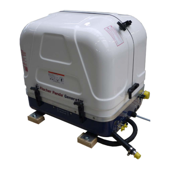
Page 33: The Panda Generator
The Panda Generator 4. The Panda Generator 4.1 Type plate at the Generator Fig. 4.1-1: Type plate at the generator - Picture shows 4000s SC Fig. 4.1-2: Discription type plate 9.2.16 Kapitel/Chapter 4: The Panda Generator - Seite/Page 33... -
Page 34: Description Of The Generator
The Panda Generator 4.2 Description of the Generator 4.2.1 Right side view - Panda 4K PMS Fig. 4.2.1-1: Right side view Thermostat housing Connection point for external ventilation valve DC alternator Starter motor Oil filter Thermo switch Fuel filter Heat exchanger... -
Page 35: Left Side View - Panda 4K Pms
The Panda Generator 4.2.2 Left side view - Panda 4K PMS Fig. 4.2.2-1: Left side view 04 05 Gernerator terminal box Sound cover base part Thermo switch at cylinder head Fuel filter Generator housing with coil Oil dipstick Failure bypass switch... -
Page 36: Front View - Panda 4K Pms
The Panda Generator 4.2.3 Front view - Panda 4K PMS Fig. 4.2.3-1: Front view Thermostat housing Oil drain hose Ventilation screw solenoid valve Cable for remote control panel Raw water pump Passage for starter battery cables Fuel filter Connections to external expansion tank... -
Page 37: Back View - Panda 4K Pms
The Panda Generator 4.2.4 Back view - Panda 4K PMS Fig. 4.2.4-1: Back view Capacitors Generator front plate Heat exchanger Sound cove base part Thermo switch Generator terminal box 9.2.16 Kapitel/Chapter 4: The Panda Generator - Seite/Page 37... -
Page 38: View From Above - Panda 4K Pms
The Panda Generator 4.2.5 View from above - Panda 4K PMS Fig. 4.2.5-1: View from above Capacitors Raw water pump Generator terminal box Regulator for DC alternatort Valve cover Thermo switch at cylinder head Fuel stop solenoid Heat exchanger Oil filler neck... -
Page 39: Right Side View - Panda 5K Pms
The Panda Generator 4.2.6 Right side view - Panda 5K PMS Fig. 4.2.6-1: Right side view Thermostat housing Connection point for external ventilation valve DC alternator Starter motor Oil filter Thermo switch Sound cover base part Heat exchanger 9.2.16 Kapitel/Chapter 4: The Panda Generator - Seite/Page 39... -
Page 40: Left Side View - Panda 5K Pms
The Panda Generator 4.2.7 Left side view - Panda 5K PMS Fig. 4.2.7-1: Left side view Gernerator terminal box Sound cover base part Generator housing with coil Fuel filter Failure bypass switch Raw water pump Actuator Oil dipstick DC terminal with relays and fuses Fuel solenoid valve Boost electronic Seite/Page 40 - Kaptitel/Chapter 4: The Panda Generator... -
Page 41: Front View - Panda 5K Pms
The Panda Generator 4.2.8 Front view - Panda 5K PMS Fig. 4.2.8-1: Front view Thermostat housing Cable for remote control panel Raw water pump Passage for starter battery cables Fuel filter Connections to external expansion tank Raw water in Exhaust out Fuel in/out Connection point for external ventilation valve Passage for fuel pump cable... -
Page 42: Back View - Panda 5K Pms
The Panda Generator 4.2.9 Back view - Panda 5K PMS Fig. 4.2.9-1: Back view Capacitors Generator front plate Heat exchanger Sound cove base part Thermo switch Generator terminal box Seite/Page 42 - Kaptitel/Chapter 4: The Panda Generator 9.2.16... -
Page 43: View From Above - Panda 5K Pms
The Panda Generator 4.2.10 View from above - Panda 5K PMS Fig. 4.2.10-1: View from above Capacitors Regulator for DC alternatort Generator terminal box Thermo switch at cylinder head Valve cover Heat exchanger Fuel stop solenoid DC alternator Oil filler neck Thermostat housing Raw water pump 9.2.16... -
Page 44: Details Of Functional Units
The Panda Generator 4.3 Details of functional units 4.3.1 Control panel The control panel is fitted with various monitoring functions, which increase functional reliability and operating safety of the generator. Various parts of the generator are monitored with sensors which, when triggered, generate an error message and can shut down generator operation under certain circumstances to prevent damage. -
Page 45: Components Of Cooling Water System (Raw Water + Fresh Water)
The Panda Generator 4.3.2 Components of cooling water system (raw water + fresh water) Fig. 4.3.2-1: Two circle system 9.2.16 Kapitel/Chapter 4: The Panda Generator - Seite/Page 45... -
Page 46: The Fuel And Combustion Air System
The Panda Generator 4.3.3 The fuel and combustion air system Fig. 4.3.3-1: Fuel and combustion air circle Seite/Page 46 - Kaptitel/Chapter 4: The Panda Generator 9.2.16... -
Page 47: Sensors And Switches For Operation Surveillance
The Panda Generator 4.3.4 Sensors and switches for operation surveillance Thermo-switch at cylinder head Fig. 4.3.4-1: TThermo-switch at cylinder head The thermo-switch at the cylinder head serves to monitor the generator temperature. Thermo-switch at water-cooled exhaust elbow Fig. 4.3.4-2: Thermo-switch at exhaust elbow This thermo switch is located at the water-cooled exhaust elbow union and serves to monitor the temperature of the fresh water cooling system. -
Page 48: The Lubrication Circuit
The Panda Generator Oil pressure switch Fig. 4.3.4-4: Oil pressure switch In order to be able to monitor the lubricating oil system, an oil pressure switch is built into the system. 4.3.5 The lubrication circuit Fig. 4.3.5-1: Lubrication circuit Seite/Page 48 - Kaptitel/Chapter 4: The Panda Generator 9.2.16... -
Page 49: Generator Operation Instruction
Generator operation instruction 5. Generator operation instruction 5.1 Personal requirements Only instructed persons are allowed to run the generator. Instructed Persons has read the manual of the generator and all ancillary components and external equipment. He must be acquaint with the specific risks and safety instruc- tions. -
Page 50: Pre-Heating The Diesel Motor
It is harmless for the generator to deliver full nominal power for 2-3 hours. The hole conception of the Fischer Panda generator make sure, that the full power operation at extreme condition will not increase the engine temperatures over. Please note that the emissions of the generator also increase at full power operation. -
Page 51: Protection Conductor
5.3.5 Operating control system on the Fischer Panda generator Fischer Panda generators are equipped with various sensors/temperatures switches. The combustion engine is fur- ther equipped with a oil pressure control switch, which switches the motor off, if the oil pressure sinks to a particular level. -
Page 52: Starting The Generator - See Remote Control Panel Data Sheet
Generator operation instruction 5.6 Starting the generator - see remote control panel data sheet The instructions and regulations of the remote control Note: panel data sheet must be respected. Respect the safety instruction in front of this manual. 5.7 Stopping the generator - see remote control panel data sheet The instructions and regulations of the remote control Note: panel data sheet must be respected. -
Page 53: Installation Instructions
Damages caused by faulty or incorrect installation are not covered by the warranty. 6.1 Personal requirements The described installation must be done by a technical trained person or a Fischer Panda service point. 6.1.1 Hazard notes for the installation see “Safety first!” on Page 10. - Page 54 Installation Instructions -Warning!: Danger of fire Oil and fuel vapours can ignite on contact with ignition sources. Therefore: • No open flames during work on the generator. • Do not smoke. • Remove oil and fuel residues from the generator and floor. Danger!: Danger of poisoning Contact with engine oil, antifreeze and fuel can result in .
-
Page 55: Preparing The Base - Placement
Installation Instructions 6.2 Preparing the base - Placement Since Panda generators have extremely compact dimensions, they can be installed in tight locations. Attempts are sometimes made to install them in almost inaccessible places. Please consider that even almost maintenance-free machinery must still remain accessible at least at the front (drive belt, water pump) and the service-side (actuator, dipstick). -
Page 56: Installation Of The Cooling System - Raw Water
Installation Instructions 6.4 Installation of the cooling system - raw water 6.4.1 General Information The genset should have its own raw water (coolant water) inlet and should not be connected to any other engine systems. Ensure that the following installation instructions are complied with: For the avoidance of galvanic corrosion, refer to the chapter „Service instruction for marine generators (corrosion protection)“. -
Page 57: Generator Installation Above Waterline
A repair is then very expensive. Replacement impeller and also a spare pump should always be on board. The old pump can be sent back to Fischer Panda. Installation above water level Fig. 6.4.4-1: Installing the generator above the water level 1. -
Page 58: Generator Installation Below Waterline
Installation Instructions 6.4.5 Generator Installation below waterline If the generator cannot be attached at least 600 mm above the waterline, a vent valve must be installed at the raw water line. Possible heeling must be taken into consideration if installed Fig. -
Page 59: Generator Housing Cooled By Raw Water
Installation Instructions ...and bend it upwards. Fig. 6.4.5-3: Connection vent valve Both hose ends must be led out outside of the sound cover to one point, if possible 600 mm over the waterline at the mid- ships line. The valve is connected at the highest place with the two hose ends. -
Page 60: Indirect Cooling Of The Genset Housing (By The Heat Exchanger)
Installation Instructions 6.4.7 Indirect cooling of the genset housing (by the heat exchanger) Fig. 6.4.7-1: Installation scheme indirect cooling of the genset housing 1. Vent valve 5. Raw water filter 2. Exhaust manifold 6. Water cock 3. Raw water pump (Raw water impeller pump) 7. -
Page 61: Ventilating At The First Filling Of The Internal Cooling Water Circuit
Installation Instructions The external cooling water expansion tank may be filled Attention! only up to the lower edge of the lower tension tape (see note „max“) in the maximum filling level in cold condition. 6.5.2 Ventilating at the first filling of the internal cooling water circuit Expansion Tank Fig. -
Page 62: Pressure Test For Controlling The Cooling Water Circuit
Installation Instructions 7. Fill up the expansion tank. 8. Close the expansion tank. 9. Re-ventilating process 10 Operating hours after the first start-up (and if necessary) Also after the first implementing a small amount of air can be reside in the cooling circuit. To ensure an immaculate and actual operating of the cooling system the ventilating process must be repeated casual in the next few days (weeks, if necessary). -
Page 63: Scheme For Freshwater Circuit At Two Circuit Cooling System
Installation Instructions 6.5.4 Scheme for freshwater circuit at two circuit cooling system Fig. 6.5.4-1: Scheme for freshwater circuit at two circuit cooling system 1. Expansion tank 4. Freshwater pump 2. Exhaust manifold 5. Heat exchanger 3. Thermostat housing 6. Cooling water connection block 9.2.16 Kapitel/Chapter 6: Installation Instructions - Seite/Page 63... -
Page 64: Installation Of The Water Cooled Exhaust System
Installation Instructions 6.6 Installation of the water cooled exhaust system 6.6.1 Installation of the standard exhaust system The generator exhaust system must remain completely independent and separate from the exhaust system of any other unit(s) on board. The water lock must be installed at the lowest point of the exhaust system. An optional noise insulated water lock can also be installed. -
Page 65: Installation Of The Waterlock
Installation Instructions Installation of the waterlock Pay attention to the right flow direction throught the Note!: waterlock. Unfortunately, it can occasionally occur that, because of an disadvantageous mounting position of the waterlock, sea water gets into the diesel engines’ combustion chamber. This disables the diesel engine by irreversible damages. Quite frequently, this leads to discussions during which the parties involved in the yachts’... -
Page 66: Installation Area Of The Waterlock
Installation Instructions b) Position of the venting valve is too far from the ships’ center line. The water reaches the exhaust area when the ship is tilted. c) The venting valve does not work, because it jams or it is clotted. (The venting valve’s function needs to be checked regularly.) As it consistently happens that functioning risks are not realised during the laying of the exhaust hose, the following explanations refer explicitly to the exhaust hose. -
Page 67: Ideal Position Of The Waterlock
Installation Instructions If there are any doubts, a verification can easily be made Fig. 6.7.3.0-2: Testing the cooling water level by temporarily using a clear-sighted hose (1) as exhaust hose. In that way, the cooling water level can be checked very easily. -
Page 68: Example Of The Installation Of The Waterlock Off-Center And Possible Effects
Installation Instructions Fig. 6.7.3.1-3: Tilted position 30 degrees Tilted position 30 degrees - Fig. 6.7.3.1-3 The distance of the water level, even in ideal position, changes that only 458 mm distance remain. So the critical distance is under-run already. Fig. 6.7.3.1-4: Tilted position 45 degrees Tilted position 45 degrees - Fig. - Page 69 Installation Instructions A) Installation of the waterlock 500 mm next to the generator’s center line: Fig. 6.7.3.2-1: waterlock, 500 mm next to the center line Fig. 6.7.3.2-2: Tilted position 45 degrees Tilted position 45 degrees - Fig. 6.7.3.2-2 The water level is now at the same height as the critical point at the exhaust elbow. If the ship is sailed in a tilted position of 45 degrees with an installation like this, the ingress of cooling water into the combustion chamber is inevitable.
-
Page 70: Exhaust / Water Separator
In order to reduce the noise level of the generator unit to a minimum, an optional exhaust outlet muffler can be mounted next to the through-hull fitting. Additionally there is a component at Fischer Panda, which acts as both an „exhaust goose neck“, and water separator. - Page 71 Installation Instructions Exhaust water separator Fig. 6.8-2: Exhaust water separator (1) Raw water outlet (2) Hose connector (3) Reducer (if required) (4) Hose (5) Hose connector (6) Sea cock (7) Hull outlet (8) Hose Clips 9.2.16 Kapitel/Chapter 6: Installation Instructions - Seite/Page 71...
-
Page 72: Installation Exhaust Water Separator
Installation Instructions 6.8.1 Installation exhaust water separator Fig. 6.8.1-1: Installation exhaust water separator 1. Generator 4. Silencer 2. Silencer / Water lock 5. Sea cock 3. Exhaust-Water-Separator 6. Hull outlet If the exhaust water separator was sufficiently highly installed, a goose neck is no longer necessary. The exhaust/ water separator fulfils the same function. - Page 73 Installation Instructions Fig. 6.8.1-2: Example for an unfavourable installation Example of an unfavourable installation: - Water lock not far enough below the lowest level of the generator - Distance water lock to exhaust/water separator too large 9.2.16 Kapitel/Chapter 6: Installation Instructions - Seite/Page 73...
-
Page 74: Installation Of The Fuel System
Installation Instructions 6.9 Installation of the fuel system 6.9.1 General references Inside the generator capsule itself, there is the fuel filter installed (exception: Panda 4200 and 4500). Additional fuel filters (with water separator) must be mounted outside the capsule in easily accessible places in the fuel lines between the tank intake fuel pump and the diesel motor's fuel pump. -
Page 75: Connection Of The Fuel Lines At The Tank
Installation Instructions 6.9.3 Connection of the fuel lines at the tank Lead the return fuel pipe connected to the day tank to the floor The return pipe connected to the tank must be dropped to the same depth as the suction pipe, if the generator is mounted higher than the tank, in order to prevent fuel running back into the tank after the motor has been switched off, which can lead to enormous problems, if the generator is switched off for a long period. -
Page 76: Generator Dc System Installation
Installation Instructions 4. The air vent screw can be screwed in again, as soon as fuel runs out without bubbles. Then release the depressing the failure bypass switch. 5. Starting the generator Now the generator can be started by pushing the „START“-button. The generator should start after a short while. One of the pipe union nuts of an injection hose has to be unscrewed, should the unit not start;... - Page 77 Installation Instructions To avoid large voltage drops the battery should be NOTE: installed as near as possible to the generator. The positive terminal of the battery is attached at the red cable, the negative pole at the blue cable. It must be guaranteed that first the cables are attached at A t t e n t i o n ! : C o n s i d e r c o r r e c t c o n n e c t i o n the generator and then at the battery.
- Page 78 Installation Instructions Negative battery cable Fig. 6.10.1-2: Negative battery cable The negative (-) battery cable is connected to the engine foot. Note! The battery negative pole may not be connected with the boat ground or with the protective grounding of the 120 V installation! DC-relay Fig.
-
Page 79: Connection Of The Remote Control Panel - See Separate Control Panel Manual
Installation Instructions Fig. 6.10.1-5: Battery installation - Scheme 1. Generator 3. Fuse 2. Battery block 4. Battery main switch 6.10.2 Connection of the remote control panel - see separate control panel manual 9.2.16 Kapitel/Chapter 6: Installation Instructions - Seite/Page 79... -
Page 80: Generator Ac System Installation
Installation Instructions 6.11 Generator AC system installation Before the electrical system is installed, READ the Attention! SAFETY INSTRUCTIONS of this manual FIRST! Be sure that all electrical installations (including all safety systems) comply with all required regulations of the regional authorities. This includes lightening conductor, personal protection switch etc. - Page 81 Installation Instructions The fuses must be of the slow type. A 3-way motor protection switch must be installed to protect the electrical motor. Required fuses see rated current on the type plate Required cable cross-sections The following recommended electrical cable dimensions (cross sections) are the minimum required sizes for a safe installation (see section 9.3, “Cable cross section,”...
-
Page 82: Insulation Test
Installation Instructions 6.11.1 Insulation test Once the electrical system installation is complete, a Attention: ground insulation test must be performed as follows: 1. Switch off all on-board electrical devices. 2. Start the generator. 3. Measure the AC-voltage with a voltmeter (adjust to Volt/AC) between a. -
Page 83: Maintenance Instructions
7.1 Personal requirements All maintenance, if not special marked, can be done by the trained persons. Further maintenance must be done by technical personal or Fischer Panda service points. 7.2 Hazard notes for the maintenance Follow the general safety instruction at the front of this Notice!: manual. - Page 84 Maintenance Instructions Contact with engine oil, antifreeze and fuel can result in Danger!: Danger of poisoning damage to health. Therefor: • Avoid skin contact with engine oil, fuel and antifreeze. • Remove oil and fuel splashes and antifreeze from the skin immediately.
-
Page 85: Environmental Protection
Maintenance Instructions 7.3 Environmental protection Danger to the environment due to mishandling! Environmental protection. Significant environmental damage can occur, particularly for incorrect disposal, if environmentally hazardous operating materials are mishandled. Therefore: • Always observe the instructions mentioned below. • Take immediate action if environmentally hazardous materials reach the environment. -
Page 86: Oil Change Intervals
Maintenance Instructions 7.6 Oil change intervals The first oil change is to be accomplished after a period of operation from 35 to 50 hours. Afterwards the oil is to be changed after 150 hours. For this, the oil SAE30 for temperatures over 20°C and SAE20 for temperatures between 5°C and 20°C is to be used. -
Page 87: Refilling Oil
• if the oil-level is under the minimum mark by less than 50h, there might be a technical problem! In that case, we recommend going to a shop or a Fischer Panda service point. • if the oil is cloudy or even „creamy“, coolant might have mixed with the oil. See a garage or a Fischer Panda service point immediately. -
Page 88: Replacement Of Engine Oil And Engine Oil Filter
Maintenance Instructions 7.8 Replacement of engine oil and engine oil filter You require: - Engine oil. See attachment. - New oil filter (not with generators with EA300 engines) - Sealing for oil drain screw - Personal protective gear - Container to collect used oil (heat resistant and of sufficient size) - Open-ended wrench for oil drain screw - Paper towels and cloth... - Page 89 Maintenance Instructions 2. Loosen oil filling cap Fig. 7.8-1: Oil filling cap Unscrew the oil filling cap. This is necessary, because otherwise a vacuum will form and the oil can not completely drain off. Sample picture 3. Open oil drain screw. Fig.
-
Page 90: After The Oil Change
Maintenance Instructions Oil screen with generators with EA300 engines Fig. 7.8-4: Oil screen The oil screen should be cleaned every 500 operating hours: to do so follow the instructions in the engine manual. Use spanner size 17 mm. Sample picture 6. -
Page 91: Verifying The Starter Battery And (If Necessary) The Battery Bank
Maintenance Instructions 7.9 Verifying the starter battery and (if necessary) the battery bank Check the condition of the battery. Proceed here as prescribed by the battery manufacturer. If from the battery manufacturer not otherwise mentioned. 7.9.1 Battery 7.9.1.1 Check battery and cable connections •... -
Page 92: Check Electrolyte Density
Maintenance Instructions 7.9.1.3 Check electrolyte density • Measure the electrolyte density of individual cells with a Fig. 7.9.1.3-1: Battery commercial hydrometer. The hydrometer reading (see table on following page) indicates the battery’s state of charge. During measurement, the temperature of the electrolyte should preferably be 20 °C. - Page 93 Maintenance Instructions 2. Press failure bypass switch and keep firmly pressed. Fig. 7.10-1: Failure bypass switch The electrical fuel pump must be audible. Switching on and off the solenoid valve at the generator will be audible by pressing the failure bypass switch (if capsule removed).
-
Page 94: Replacement Of The Fuel Filter
Maintenance Instructions 7.10.1 Replacement of the fuel filter Exchanging the filter, depending upon fuel contamination, Fig. 7.10.1-1: Fuel Filter should take place after 300 operational hours at the very least. The inlet must be clamped, before exchanging the filter. Remove the hoses from the used filter and fasten them to the new filter. -
Page 95: Checking The Water Separator In The Fuel Supply
Maintenance Instructions 2. Unscrew the filter element from the mount (left hand Fig. 7.10.1.1-3: Fuel filter rotation). 3. Screw the new filter element into the mount. Fig. 7.10.1.1-4: Fuel filter 4. Lubricate the sight glasses o-ring with a heat resistant grease (Specification: Antiseize) and screw the sight glass back into its mount (right hand rotation). -
Page 96: Replace The Air Filter Mat
Maintenance Instructions 7.11.1 Replace the air filter mat 1. Open the air suction housing by loosen the six screws on Fig. 7.11-1: Air suction housing the housing cover. Use spanner size 8 mm. 2. Change the air filter mat. Fig. 7.11-2: Opened air suction housing 3. - Page 97 Maintenance Instructions 2. Tip the two fasteners 90°. Fig. 7.11.2-2: Air suction housing with pull out holder 3. Pull the filter mat holder out. Fig. 7.11.2-3: Air suction housing with pull out holder 4. Replace the air filter mat. Fig. 7.11.2-4: Air suction housing with pull out holder 5.
-
Page 98: Alternative Replacement Of The Air Filter At Housing With Snap Fasteners
Maintenance Instructions 7.11.3 Alternative replacement of the air filter at housing with snap fasteners 1. Open the combustion air housing by loosening the closure Fig. 7.11.3-1: Air suction housing on the right side of the housing. 01. Closure 2. Open the combustion air housing by loosening the closure Fig. -
Page 99: Ventilation Of The Coolant Circuit / Freshwater
Maintenance Instructions 7.11.4 Ventilation of the coolant circuit / freshwater Special notes for the ventilation of the cooling system Attention If the cooling water is drained, or if other air has entered the cooling system, it is necessary to ventilate the cooling system. - Page 100 Maintenance Instructions 2. Open the ventilating screw on the thermostat casing. Fig. 7.11-3: Ventilating screw on the thermostat housing Use spanner size 10 mm. 3. Pour cooling water into the cooling water filling necks. Fig. 7.11-4: Cooling water filler cap (At generators without filler, The cooling water can be filled into the external expansion tank instead) 4.
-
Page 101: V-Belt Replacement For The Internal Cooling Water Pump
Maintenance Instructions 7.12 V-belt replacement for the internal cooling water pump The V-belt wears in a short time due to high ambient temperature within the closed capsule (approx. 85 °C). The air in the generator capsule is not only warm but also very dry. Therefore it is possible, that the „softener“ in the rubber composers wear after a very short time of operation. - Page 102 Maintenance Instructions 3. The alternator must be pressed in the direction of the Fig. 7.12.0-3: Alternator thermostat housing. 4. Exchange the V-belt. Sample Picture 5. Afterwards, the V-belt must be tightened again. Fig. 7.12.0-4: V-belt 6. The V-belt must be tightened in such a way, that it is possible to press it about approx.
-
Page 103: The Raw Water Circuit
Maintenance Instructions 7.13 The raw water circuit 7.13.1 Clean raw water filter The raw water filter should be released regularly from Fig. 7.13.1-1: Raw water filter arrears. In each case the water cock must be closed before. It is mostly sufficient to beat the filter punnet. If water should seep through the cover of the raw water filter, this may be sealed in no case with adhesive or sealant. -
Page 104: Replacement Of The Impeller
Maintenance Instructions 7.14.1 Replacement of the impeller Close the raw water stop cock. Fig. 7.14.1-1: Raw water cock Representative picture Raw water pump on the front side of the genset. Fig. 7.14.1-2: Raw water pump Representative picture Remove the cover of the raw water pump by loosen the Fig. -
Page 105: Check And Discharge The Capacitors
Maintenance Instructions Fig. 7.14.1-4: Impeller pump Pull to the impeller with a multigrip pliers of the wave. Mark the impeller, to make sure that these is used in the correct position at re-installation. Representative picture Check to the impeller for damage and replace it if Fig. - Page 106 Maintenance Instructions The capacitors can be checked using a multimeter with capacitor measuring. The capacitors fitted inside the cabinet are discharged over the soldered resistor at every capacitor. The discharge over the discharge reactor (see special tools) is security because the capacitor voltage is lethal. Discharge the capacitor - single phase Fig.
- Page 107 Maintenance Instructions Checking the electrical connections to the Capacitor It must be ensured that the electrical connections to the capacitor are always tight fitting. Loose connections with transitional resistance can mean that the contact surfaces will become heated externally. This can lead to faster deterioration of the capacitors.
-
Page 108: Replacing The Electric Starter
Maintenance Instructions 7.15 Replacing the electric starter The described procedure is representative for Fischer Panda NOTE:Representative procedure generators. The original location of the item must be taken from the generator description of this manual. All replacements and repairs should be done by a trained person. - Page 109 Maintenance Instructions 3. Pull off rubber cap. Fig. 7.15-3: Electric starter 4. Loosen hex nut with wrench with W.A.F. 13 mm and remove the electric connections. 5. Loosen the lower attachment screw with a hex socket Fig. 7.15-4: Electric starter wrench.
- Page 110 Maintenance Instructions The upper attachment screw is visible from up top, view Fig. 7.15-6: Electric starter between engine and exhaust manifold. 6. Slide the socket wrench fitted with both extensions under the exhaust manifold and insert in the hex socket screw. Loosen upper attachment screw.
-
Page 111: Replacing The Oil Pressure Switch
Maintenance Instructions 7.16 Replacing the oil pressure switch The described procedure is representative for Fischer Panda NOTE:Representative procedure generators. The original location of the item must be taken from the generator description of this manual. All replacements and repairs should be done by a trained person. -
Page 112: Replacing The Oil Pressure Sensor (Optional Component)
Maintenance Instructions 7.16.1 Replacing the oil pressure sensor (optional component) 1. Unscrew both connectors (01) on the oil pressure sensor. Fig. 7.16.1-1: Oil pressure sensor 2. Loosen and remove oil pressure sensor 6R3 using a Fig. 7.16-2: Oil pressure sensor wrench with W.A.F. -
Page 113: Replacing The Operating Current Relays
Maintenance Instructions 7.17 Replacing the operating current relays The described procedure is representative for Fischer Panda NOTE:Representative procedure generators. The original location of the item must be taken from the generator description of this manual. All replacements and repairs can be done by the user. -
Page 114: Replacing The Fuses
Maintenance Instructions 7.18 Replacing the fuses The described procedure is representative for Fischer Panda NOTE:Representative procedure generators. The original location of the item must be taken from the generator description of this manual. This replacement can be done by the user. -
Page 115: Replacing A Thermoswitch
Maintenance Instructions 7.19 Replacing a thermoswitch The described procedure is representative for Fischer Panda NOTE:Representative procedure generators. The original location of the item must be taken from the generator description of this manual. All replacements and repairs should be done by a trained person. - Page 116 Maintenance Instructions 3. Disconnect electric supply line of the thermoswitch. Fig. 7.19-3: Thermoswitch 4. Loosen thermoswitch with a wrench with W.A.F. 22 mm. Fig. 7.19-4: Thermoswitch 5. Before installing the new thermoswitch, check the label for Fig. 7.19-5: Thermoswitch correct item. 6.
-
Page 117: Replacing The Injection Nozzles
Maintenance Instructions 7.20 Replacing the injection nozzles The described procedure is representative for Fischer Panda NOTE:Representative procedure generators. The original location of the item must be taken from the generator description of this manual. All replacements and repairs should be done by a trained person. - Page 118 Maintenance Instructions 3. Loosen the union nut on the injection lines (1). Wrench Fig. 7.20-3: Injection nozzles with W.A.F. of 17 mm. For assembly: • Blast dust out of the lines using compressed air. Then, reassemble the lines by proceeding in the reverse order of steps.
-
Page 119: Replacing The Glow Plugs
(1) Phillips screwdriver (2) Injection nozzle (3) Injection nozzle gasket (4) Heat ring seal 7.21 Replacing the glow plugs The described procedure is representative for Fischer Panda NOTE:Representative procedure generators. The original location of the item must be taken from the generator description of this manual. All replacements and repairs should be done by a trained person. - Page 120 Maintenance Instructions Figures similar! Fig. 7.21-2: Glow plugs 2. Remove the three hex screws using a size 7 mm socket wrench . 3. Remove the glow plug connector. Fig. 7.21-3: Glow plugs 4. Loosen the glow plug using a socket wrench with a long Fig.
- Page 121 Maintenance Instructions 5. Remove glow plug. Fig. 7.21-5: Glow plugs 6. To reinstall, reverse the order of steps. 9.2.16 Kapitel/Chapter 7: Maintenance Instructions - Seite/Page 121...
- Page 122 Maintenance Instructions Leere Seite / Intentionally blank Seite/Page 122 Kapitel/Chapter 7: Maintenance Instructions 9.2.16...
-
Page 123: Generator Faults
Generator Faults 8. Generator Faults 8.1 Personal requirements The work described here, unless otherwise indicated, are performed by the operator. More repair work may be performed only by specially trained personnel or by authorized repair shops (Fischer Panda service points). This is especially for working on the valve timing, fuel injection system and the engine repair. 8.2 Hazard notes for the troubleshooting Follow the general safety instruction at the front of this Notice!:... - Page 124 Generator Faults Contact with engine oil, antifreeze and fuel can result in Danger!: Danger of poisoning damage to health. Therefor: • Avoid skin contact with engine oil, fuel and antifreeze. • Remove oil and fuel splashes and antifreeze from the skin immediately.
-
Page 125: Tools And Measuring Instruments
Generator Faults 8.3 Tools and measuring instruments In order to be able to manage disturbances while driving, the following tools and measuring instruments should belong to the equipment kept on board: • Multimeter for voltage (AC), frequency and resistance • Measuring instrument for inductance •... -
Page 126: Troubleshooting Table And Flowchart
Generator Faults 8.4 Troubleshooting table and flowchart 8.4.1 Generator output voltage too low For 50 Hz versions: less than 200 V Cause Solution Generator is overloaded. Reduce the electrical load (switch off load) Motor is not reaching the rated rpm. Refer to „motor faults“... - Page 127 Generator Faults Cause Solution Lack of fuel. Check fuel supply. Glow-plugs not working correctly. Check glow plugs and heating time. Too much air in fuel lines. Test fuel system for leakage. Bleed air from fuel system (refer to section „Bleeding Air from Fuel System“). Fuel-filter blocked.
-
Page 128: Motor Does Not Achieve Enough Speed During Starting Process
Generator Faults 8.4.7 Motor does not achieve enough speed during starting process Cause Solution Starter battery voltage insufficient. Check battery. Damaged bearing(s) piston (seized). Repairs need to be carried out by Kubota-Service. (refer to Kubota motor-manual) Cooling water in combustion chamber. 1. -
Page 129: Sooty, Black Exhaust
Generator Faults Cause Solution Lack of oil pressure sensor tripped). Is indicated on the remote control Check oil-level and if necessary top up. panel. Check motor's oil-pressure and have repaired by Kubota-Service if necessary. 8.4.12 Sooty, black exhaust Cause Solution Generator is overloaded. -
Page 130: Troubleshooting Flowcharts
Generator Faults 8.4.15 Troubleshooting flowcharts Fig. 8.4.15-1: Troubleshooting flowchart - Page 1 Page 1 Generator Install Generator installed Before you start, please read the manual and make yourself familiar with the generator. Correct Exchange Fuse Wiring Fuse on the back Wiring correct? Generator starts Panel works... - Page 131 Generator Faults Fig. 8.4.15-2: Troubleshooting flowchart - Page 2 Page 2 Generator runs Go to page 1 Defective load/ Restore residual Exchange cable *1 Exchange cable *1 Switch off load magnetism *1 Generator runs Residual magnetism Cable AC-out ok? Cable generator AC Box ok? Load switched on? without load - No voltage...
-
Page 132: Details And Explanations Concerning The Troubleshooting Flowchart
Generator Faults 8.4.15.1 Details and explanations concerning the troubleshooting flowchart Each failure position in the flowchart above contains a reference number. With this reference number, the corresponding work steps can be taken from the list below. 1.1 Fuse at the remote control panel. Execute the fuse exchange as indicated in the data sheet of your remote control panel. - Page 133 Repair the connection assembly. 9.1 Defective cable to the AC-Box. Get the cable to the AC-Box exchanged by a Fischer Panda Service point/Service Centre. The operations are to be executed by a trained Attention: Voltage up to 400 V - Danger to life! professional only! 9.2 Defective cable AC out.
- Page 134 11.4 Disrupted measuring voltage to VCS. Get the measuring voltage cable connected/exchanged by a Fischer Panda Service point/Service Centre. Attention: Voltage up to 400 V - Danger to life! The operations are to be executed by a trained professional only! 11.5 Generator is overloaded.
- Page 135 Generator Faults 13.4 Heat exchanger blocked. Get the heat exchanger checked and repaired by a Fischer Panda Service point/Service Centre. 13.5 Defective temperature switch, possibly loose contact/cable break. Get the temperature switch checked and repaired by a Fischer Panda Service point/Service Centre.
-
Page 136: Versions Of The Generator Power Terminal Box
Generator Faults 8.5 Versions of the generator power terminal box Generator power terminal box 230 V / 50 Hz Fig. 8.5.0-1: Generator output terminal box 230 V / 50 Hz In these terminal box there are the electrical connection points for the AC generator. Here is also the bridge for the protective grounding of the generator. - Page 137 Generator Faults Fig. 8.5.0-4: Wiring diagram HP3 - 400 V / 50 Hz Generator power terminal box 120 V / 60 Hz Fig. 8.5.0-5: Generator power terminal box 120 / 60 Hz Z1.2 In these terminal box there are the electrical connection points for the AC generator.
- Page 138 Generator Faults Fig. 8.5.0-6: Wiring diagram HP1 - 120 V / 60 Hz Generator power terminal box 240 / 60 Hz (208 V / 60 Hz) Fig. 8.5.0-7: Generator power terminal box 240 V / 60 Hz In these terminal box there are the electrical connection points for the AC generator.
- Page 139 Generator Faults Fig. 8.5.0-8: Wiring diagram HP3 - 240 V / 60 Hz Generator power terminal box DVS - 120 V + 240 V / Fig. 8.5.0-9: Generator power terminal box DVS 60 Hz In these terminal box there are the electrical connection points for the AC generator.
-
Page 140: Overloading The Generator
Generator Faults Fig. 8.5.0-11: Wiring diagram DVS - 230 V + 400 V / 50 Hz 8.6 Overloading the generator Please ensure that the generator is not overloaded. This must be considered, especially with regards to multi power generators. In this case the extra load including the electrical performance can be considerably greater than the drive performance of the motor, which can eventually lead to a damaged motor. -
Page 141: Monitoring The Generator Voltage
„normally“. The Fischer Panda generators are aligned that they keep these default values during normal load. With high load or overload it can occur that the voltage drops on 190 V (95 V in the 60 Hz version) and partly still more deeply. -
Page 142: Generator Output Voltage Is Too Low
Generator Faults 8.7 Generator output voltage is too low If the AC generated is too low, then the consumers should be disconnected, one after the other, in order to reduce the load on the generator. Generally the problem is then solved. The frequency should be checked, if the output voltage is correct after the consumers have been disconnected. -
Page 143: Checking The Capacitors
Generator Faults 8.7.2 Checking the capacitors If the capacitors are to be checked, make sure that the ATTENTION! capacitors has been discharged. A visual check can give information on whether the capacitors are defective: • Dielectric leak? • Did the capacitor become longer? Multimeter Fig. -
Page 144: Measuring The Ohm Resistance Of The Generator Windings
Generator Faults 8.7.4 Measuring the ohm resistance of the generator windings If a short circuit could not be found by using a multi-meter, then the windings parts of the generator must be checked by means of an Ohmmeter that is suitable for low resistance values. •... -
Page 145: Measuring The Inductive Resistance
Generator Faults 8.7.6 Measuring the inductive resistance An Ohm measurement of a winding does not always give reliable information concerning the state of the winding. If there are resistance irregularities between the windings parts, this is a sure sign that the winding is defective. This means the opposite cannot be concluded. -
Page 146: Engine Starting Problems
Generator Faults 8.9 Engine starting problems 8.9.1 Electric fuel solenoid valve The fuel solenoid valve is located in front of the injection pump. It opens automatically, if the „START“-button is pressed on remote control panel. If the generator is switched to „OFF“, the solenoid valve closes. It takes some seconds, before the generator stops. -
Page 147: Lifting Solenoid For Motor Stop - Optional
Generator Faults This period can be reduced by pushing the button on the front of the generator. The generator can be started by means of the remote control as long as the button is depressed. The switch/ button bypasses any faults allowing the generator to run. -
Page 148: Troubleshooting Table
Generator Faults the only handling error that can be made on board that can lead to fatal consequences for both generator and operator. 8.9.4 Troubleshooting table For Troubleshooting see “Troubleshooting table and flowchart” on Page 126. Seite/Page 148 - Kaptitel/Chapter 8: Generator Faults 9.2.16... -
Page 149: Tables
Tables 9. Tables 9.1 Technical data Fig. 9.1-1: Technical data Panda 4000s Panda 4200 FCB 4500FCB Panda 4k Panda 5000 LPE Panda 4,5ND Panda 5k Type Farymann Farymann Farymann Z482 EA300 18W430 18W430 18W430 Governor mechanic mechanic mechanic mechanic Automatic start booster Cylinder Bore 82 mm... - Page 150 Tables Panda 6500 Panda 8000 Panda 9000 Panda 10000 Panda 12000 Panda 7 mini Panda 8 mini Panda 9 mini Max. power (DIN 6271-NB) at 3000 rpm 9,32 kW 9,32 kW 14,0 kW 11,6 kW 14,0 kW Rated speed 3000 rpm 3000 rpm 3000 rpm 3000 rpm...
- Page 151 Tables Panda 12000 Panda 15000 Panda 18 Panda 24 Panda 30 15 mini digital Recommend cable cross size starter battery 25 mm² 25 mm² 25 mm² 25 mm² 25 mm² cable Length 4 meter max. Max. exhaust back pressure 9,3 kPa 10,7 kPa 10,7 kPa 10,7 kPa...
- Page 152 Tables Panda 7,5-4 Panda 9-4 Panda 12-4 Panda 17-4 Panda 22-4 Stroke volume 898 cm³ 1123 cm³ 1498 cm³ 2197 cm³ 2434 cm³ Max. power (DIN 6271-NB) at 3000 rpm 17,5 kW 18,7 kW 23,3 kW 20,1 kW 31,1 kW Rated speed 1500 rpm 1500 rpm...
- Page 153 Tables Panda 30/4 Panda 30/4 Panda 40/4 Panda 50/4 Panda 70/4 Recommend cable cross size starter battery 70 mm² 70 mm² 70 mm² 70 mm² cable Length 4 meter max. Max. exhaust back pressure 4 kPa 10,7 kPa 10,7 kPa 10,7 kPa 40 Millibar 107 Millibar...
-
Page 154: Rated Current
Tables Panda 45i Rated speed 2700 rpm Idle running speed 1600 rpm Valve clearance (engine cold) 0,18 - 0,22 mm Cylinder head nut torque 93,1 - 98 Nm Compression ratio Lubrication oil capacity 9,5 l Fuel consumption ³ approx. 1,95 - 5,2 l Oil consumption max. -
Page 155: Fuel
Tables length 1 - 3 m 4 - 6 m 7 - 10 m 11 - 15 m 16 - 20 m 50mm² 225 A 200 A 175 A 150 A 125 A 70mm² 275 A 250 A 225 A 195 A 170 A 95mm²... -
Page 156: Coolant Specifications
Use a mixture of water and antifreeze. The antifreeze needs to be suitable for aluminium. The antifreeze concentration must be regularly checked in the interests of safety. Fischer Panda recommend to use the product: GLYSANTIN PROTECT PLUS/G 48 Engine coolant automotive industry Product description Product name GLYSANTIN ®... -
Page 157: Coolant Mixture Ratio
Tables 9.6.1 Coolant mixture ratio Water/antifreeze Temperature 70:30 -20°C 65:35 -25°C 60:40 -30°C 55:45 -35°C 50:50 -40°C 9.7 Diameter of conduits Fig. 9.7-1: Diameter of conduits Generator type Ø Cooling water conduit Ø Exhaust conduit Ø Fuel conduit [mm] Freshwater Seawater Supply Return... - Page 158 Tables Generator type Ø Cooling water conduit Ø Exhaust conduit Ø Fuel conduit [mm] Freshwater Seawater Supply Return [mm] [mm] [mm] [mm] Panda PMS-HD 85-4 DZ Panda PMS-HD 110-4 DZ Panda PMS-HD 130-4 DZ Seite/Page 158 - Kaptitel/Chapter 9: Tables 9.2.16...
-
Page 159: Remote Control Panel P4 Control
Remote Control Panel P4 Control 10. Remote Control Panel P4 Control Art Nr. 21.02.02.032H Bez. Remote Control Panel P4 Control Tabelle 1: Dokument Hardware Software Aktuell: R02.1 V1.00 -------------------------- Ersetzt: V1.00 -------------------------- 10.1 Remote control panel Remote control panelP4 Control The remote control panel is necessary to control the generator and to evaluate the motor/generator properties. -
Page 160: Cleaning And Replacing Parts At The Generator
Remote Control Panel P4 Control 10.1.1 Cleaning and Replacing parts at the generator Attention!: Disconnect the battery when working on the generator The battery must always be disconnected (first negative then positive pole), when work on the generator or the electrical system of the generator are made, so that the generator can not be started accidentally. -
Page 161: Front Side
Remote Control Panel P4 Control 10.2 Front side Fig. 10.2-1: Remote Control Panel - Front Side Display operating hours Warning light for engine temperature Power „ON/OFF“-button Warning light for exhaust temperature Generator „Start“-button Warning light for oil pressure Control light „Override“ 10.2.1 Back side Fig. -
Page 162: Operation Manual
Advices concerning the starter battery Fischer Panda recommends normal starter battery use. If a genset is required for extreme winter conditions, then the starter battery capacity should be doubled. It is recommended that the starter battery be regularly charged by a suitable battery-charging device (i.e., at least every 2 months). -
Page 163: Starting The Generator
Remote Control Panel P4 Control Leaks at hose connections must be immediately repaired, especially the raw water impeller pump. It is certainly possible that the raw water impeller pump will produce leaks, depending upon the situation. (This can be caused by sand particles in the raw water etc.) In this case, immediately exchange the pump, because the dripping water will be sprayed by the belt pulley into the sound insulated casing and can quickly cause corrosion. -
Page 164: Installation Of The Panel
Remote Control Panel P4 Control 3. Press „OFF“ button and switch off the generator. 4. Activate additional switches (Battery switch, fuel stop valve etc.). Never switch off the battery until the generator has Notice!: stopped. 5. If necessary, close sea cock. If the generator switches itself off with the operation with :Notice!: load for temperature reasons, must be examined... - Page 165 Remote Control Panel P4 Control T-EXH Error „exhaust temp.“. Temperature switch exhaust elbow in. Can be set up by jumper as NC or NO Gives 22 mA (12 V +) on the switch. Status is displayed by green/red LED. Oil-Press Error „oil pressure“.
-
Page 166: Jumper Configuration
Remote Control Panel P4 Control 10.5 Jumper configuration 10.5.1 Jumper configuration for the input 10.5.1.1 Jumper J101-J103 Fig. 10.5.1.1-1: Jumper J101 - J103 At the 3 pin jumpers J101-J103 the pin 3 is at the termination block side. Jumper Status Desc. -
Page 167: Jumper For Configuration Of The „Override" Time
Remote Control Panel P4 Control 10.5.2 Jumper for configuration of the „Override“ time J104 J105 J106 Test-Mode Override time [s] open open open closed open open open closed open closed closed open open open closed 0,16 closed open closed 0,08 open closed closed... - Page 168 Remote Control Panel P4 Control Seite/Page 168 - Kaptitel/Chapter 10: Remote Control Panel P4 Control 9.2.16...
Need help?
Do you have a question about the Panda 4K PMS and is the answer not in the manual?
Questions and answers