
Related Manuals for Fischer Panda Panda AGT DC 5000


Summary of Contents for Fischer Panda Panda AGT DC 5000
- Page 1 Manual Marine Generator Panda PMS AGT 6000 24 V-72 V - 6 kVA Panda AGT DC 5000 PMS - 12 V / 5 kVA Super silent technology Marine_AGT6000_12-72V_eng.R02 9.12.14...
-
Page 2: Current Revision Status
Duplication and change of the manual is permitted only in consultation with the manufacturer! Fischer Panda GmbH, 33104 Paderborn, reserves all rights regarding text and graphics. Details are given to the best of our knowledge. No liability is accepted for correctness. Technical modifications for improving the product without previous notice may be undertaken without notice. -
Page 3: Table Of Contents
4.1.2.1 User........................31 Panda Transport Box.......................... 32 4.2.1 Bolted Fischer Panda Transport Box .................. 32 4.2.2 Fischer Panda Transport Box with metal tab closure ............32 Transport and Loading/Unloading ...................... 32 9.12.14 Inhalt/Contens Seite/Page 3... - Page 4 Inhalt / Contens 4.3.1 Transporting the generator ....................32 4.3.2 Loading/unloading of the generator ..................32 Scope of delivery ..........................33 4.4.1 PM generator ........................33 4.4.2 Opening the MPL sound insulation capsule ................ 35 4.4.3 Opening the GFK sound insulation capsule ..............
- Page 5 Installation of the cooling system - raw water ..................73 6.5.1 General information ......................73 6.5.2 Fischer Panda installation kit - raw water ................73 6.5.3 Installation of the through hull fitting in Yachts - scheme ........... 75 6.5.4 Quality of the raw water sucking in line ................
- Page 6 Inhalt / Contens Environmental protection ........................117 Maintenance interval ......................... 117 General maintenance instructions ....................117 7.5.1 Checks before each start ....................117 7.5.2 Check of Hoses and rubber parts in the sound insulated capsule ........117 Oil circuit maintenance........................
- Page 7 Troubleshooting ..........................151 9.1.1 Generator voltage too low ....................151 9.1.2 Generator voltage too high ....................151 9.1.3 Generator voltage fluctuates .................... 152 9.1.4 Motor does not turn over when starting ................152 9.1.5 Motor turns over but does not start ................. .. 152 9.1.6 Motor does not turn over at normal speed during the start process .......
- Page 8 12.7.3 Klemmenbelegung ......................185 12.8 Master-Slave Adapter - optional ..................... .. 185 12.8.1 Fischer Panda Art. Nr. 21.02.02.015P, 12 V-Version ............185 12.8.2 Fischer Panda Art. Nr. 21.02.02.015P, 24 V-Version ............186 12.8.3 Anschlussklemmen: ......................186 12.8.4...
- Page 9 Not only do you have a Fischer Panda generator on board, you also have worldwide support from the Fischer Panda Team. Please take the time to read this and find how we can support you further.
-
Page 10: General Instructions And Regulations
General Instructions and Regulations 1. General Instructions and Regulations 1.1 Safety first! These symbols are used throughout this manual and on labels on the machine itself to warn of the possibility of personal injury of lethal danger during certain maintenance work or operations. Read these instructions carefully. Can cause acute or chronic health impairments or death WARNING: Hazardous materials even in very small quantities if inhaled, swallowed, or... - Page 11 General Instructions and Regulations Touching of the corresponding parts and systems is PROHIBITED: Do not touch prohibited. Danger for life! Working at a running generator can DANGER: Automatic start-up result in severe personal injury. The generator can be equipped with a automatic start device. This means, an external signal may trigger an automatic start-up.
- Page 12 General Instructions and Regulations Warning of substances that may cause an explosion under WARNING: Explosion hazard certain conditions, e.g. presence of heat or ignition sources. Warning of hot surfaces and liquids. Burn/scalding hazard. WARNING: Hot surface Warning of substances that cause chemical burns upon WARNING: Danger due to corrosive substances, contact.
- Page 13 General Instructions and Regulations Wearing the applicable snugly fitting protective clothing MANDATORY INSTRUCTION: Wear snugly fitting provides protection from hazards and can prevent damage to protective clothing (PPE). your health. Wearing hearing protection provides protection from acute MANDATORY INSTRUCTION: Wear hearing and gradual hearing loss.
-
Page 14: Tools
General Instructions and Regulations 1.2 Tools These symbols are used throughout this manual to show which tool must be used for maintenance or installation. Spanners W.A.F X = width across flats of X mm Hook wrench for oil filter Screw driver, for slotted head screws and for Phillips head screws Multimeter, multimeter with capacitor measuring unit Socket wrench set Hexagon socket wrench set... - Page 15 General Instructions and Regulations Clamp-on ammeter (DC for synchronous generators; AC for asynchronous generators) Torque wrench 9.12.14 Kapitel/Chapter 1: General Instructions and Regulations - Seite/Page 15...
-
Page 16: Manufacturer Declaration In Accordance With The Machinery Directive 2006/42/Ec
• You will receive free upgrades as necessary. Additional advantages: Based on your complete data record, Fischer Panda technicians can provide you with fast assistance, since 90 % of the disturbances result from defects in the periphery. Problems due to installation errors can be recognized in advance. -
Page 17: Safety Instructions - Safety First
General Instructions and Regulations 1.5 Safety Instructions - Safety First! 1.5.1 Safe operation Careful handling of the equipment is the best insurance against an accident. Read the manual diligently, and make sure you understand it before starting up the equipment. All operators, regardless of their experience level, shall read this manual and additional pertinent manuals before commissioning the equipment or installing an attachment. -
Page 18: Safe Handling Of Fuels And Lubricants
General Instructions and Regulations 1.5.5 Safe handling of fuels and lubricants Keep fuels and lubricants away from naked fire. Before filling up the tank and/or applying lubricant, always shut down the generator and secure it against accidental start-up. Do not smoke and avoid naked flame and sparking near fuels and the generator. Fuel is highly flammable and may explode under certain conditions. -
Page 19: Safety Precautions Against Burns And Battery Explosions
Do not mix different anti-freeze agents. The mixture may cause a chemical reaction generating harmful substances. Use only anti-freeze that was approved by Fischer Panda. Protect the environment. Collect drained fluids (lubricants, anti-freeze, fuel), and dispose of them properly. -
Page 20: Implementation Of Safety Inspections And Maintenance
General Instructions and Regulations 1.5.10 Implementation of safety inspections and maintenance Disconnect the battery from the engine before performing service work. Affix a sign to the control panel - both the main and the corresponding slave panel - with the instruction “DO NOT START UP - MAINTENANCE IN PROGRESS“... -
Page 21: Protective Conductor And Potential Equalisation
General Instructions and Regulations 1.6.1.1 Protective conductor and potential equalisation: Electric current below 48 V may be life-threatening. Fort this reason systems are grounded with a protective conductor. In connection with a RCD the current supply will be disconnected in case of a failure. Appropriate safety precautions like the RCD and corresponding fuses have to be provided by the customer to guarantee a save operation of the generator. -
Page 22: Safety Instructions Concerning Cables
General Instructions and Regulations 1.6.1.5 Safety instructions concerning cables Cable types It is recommended to use cables that are in compliance with the standard UL 1426 (BC-5W2) with type 3 (ABYC section E-11). Cable cross-section The cable shall be selected taking into account the amperage, cable type, and conductor length (from the positive power source connection to the electrical device and back to the negative power source connection). -
Page 23: General Safety Instructions For Handling Batteries
The battery terminals must be protected against accidental short-circuiting. Inside the Fischer Panda generator capsule, the positive battery cable must be routed so that it is protected from heat and vibrations by means of an adequate conduit/protective sleeve. It must be installed so that it does not come into contact with rotating parts or such that heat up during operation such as pulley, exhaust manifold, exhaust pipe, and motor itself. - Page 24 Check the battery near vibrating components regularly for chafing and insulation defects. ATTENTION! For battery charger generators (Fischer Panda AGT-DC)! Prior to installation, verify that the voltage of the battery bank complies with the output voltage of the generator.
-
Page 25: Special Instructions And Hazards Of Agt-Dc Generators
Special Instructions and Hazards of AGT-DC Generators 2. Special Instructions and Hazards of AGT-DC Generators 2.1 General safety instructions for operating an AGT generator With all live systems, special safety precautions must be implemented to protect the components from fire. It is mandatory to ensure that the battery is fitted with a main switch in an easily accessible area so that the main switch can be disconnected immediately in case of danger. -
Page 26: Fire Protection Measures
Special Instructions and Hazards of AGT-DC Generators Always connect a battery as a capacitive load together with the inverter! The screws on the rectifier shall only be tightened with a torque wrench. Torque: see technical data sheet (e. g. 6 Nm mechanical and electrical connections of diode DD171N). The battery cable shall be protected with the corresponding fuses on the generator and at the batteries. -
Page 27: Additional Tools
Special Instructions and Hazards of AGT-DC Generators 2.3 Additional tools Temperature measuring device Infra-red gun 9.12.14 Kapitel/Chapter 2: Special Instructions and Hazards of AGT-DC Generators - Seite/Page 27... - Page 28 Special Instructions and Hazards of AGT-DC Generators Leere Seite / Intentionally blank Seite/Page 28 Kapitel/Chapter 2: Special Instructions and Hazards of AGT-DC Generators 9.12.14...
-
Page 29: In Case Of Emergency First Aid / Im Notfall - Erste Hilfe
In case of Emergency First Aid / Im Notfall - Erste Hilfe 3. In case of Emergency First Aid / Im Notfall - Erste Hilfe First Aid in case of accidents by electrical shocks 5 Safety steps to follow if someone is the victim of electrical shock Do not touch the injured person while the generator is running. -
Page 30: When An Adult Stops Breathing
In case of Emergency First Aid / Im Notfall - Erste Hilfe 3.1 WHEN AN ADULT STOPS BREATHING DO NOT attempt to perform the rescue breathing Warning: techniques provided on this page, unless certified. Performance of these techniques by uncertified personnel could result in further injury or death to the victim. -
Page 31: Basics
This manual is work instruction and operation instruction for the owner and user of Fischer Panda generators. The manual is the base and the guideline for the correct installation and maintenance of Fischer Panda Generators. The manual does not substitute the technical evaluation and should be used as an example guide only. -
Page 32: Panda Transport Box
4.3.1 Transporting the generator • The generator must always be upright for transport. • For transport, the Fischer Panda Transport Box shall be used for the generator. The generator shall be securely attached to the bottom of the box. • For loading/unloading, an adequate industrial truck shall be used. -
Page 33: Scope Of Delivery
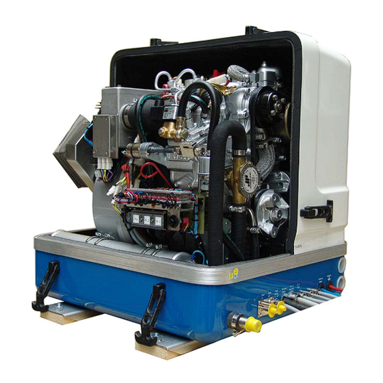
Fig. 4.3-1: Lifting yoke (example) An adequate lifting yoke shall be used for transport/ loading 4.4 Scope of delivery The Fischer Panda PMS generator system contains following components: 4.4.1 PM generator Fischer Panda Generator Fig. 4.4-1: Fischer Panda Generator representative picture Remote control panel Fig. - Page 34 Depending on the model, the rectifier unit can be build at the generator or external. If the rectifier unit is an external one, the rectifier unit is apart of the generator and must be in the delivery. It is not allowed to use an independent rectifier unit or a unit from another Fischer Panda generator. Fischer Panda Manual Fig.
-
Page 35: Opening The Mpl Sound Insulation Capsule
Basics 4.4.2 Opening the MPL sound insulation capsule To open the sound insulation capsule, the closures must Fig. 4.4-1: Sound insulation capsule, side part be rotated roughly 180° counter-clockwise. Use a flat head screwdriver. Pull the sidewalls out by gripping into the slots. -
Page 36: Opening The Gfk Sound Insulation Capsule
The decommissioning and storage must be undertaken and Note: proved regarding the operation and storage situation. Fischer Panda takes no responsibilty for damages through wrong decommissioning and storage. Downtimes are categorised in the following groups: • Short downtime (1 to 3 months) •... -
Page 37: Instructions For The Starter Battery For Extended Downtimes
- 25.2 V upper open-circuit voltage (full battery) - trickle charge full battery at 26.4 V. These values are based on a battery temperature of 20-25°C. Observe the instructions from the battery manufacturer. Fischer Panda recommends: Note: Starter battery recommendation • Install battery circuit breaker and switch to OFF on the machine. -
Page 38: Courses For Preservation
Basics 4.5.3.1 Courses for preservation: • Check battery charge status and recharge regularly, roughly every 2 months, as necessary. Observe instructions of the battery manufacturer. • Check cooling water anti-freeze level and refill as necessary. The anti-freeze agent must not be older than 2 years. The anti-freeze content shall be between 40 % and 60 % to ensure corrosion protection of the cooling water circuit. -
Page 39: Measures For Extended Downtimes / Decommissioning
Basics 4.5.4 Measures for extended downtimes / decommissioning Downtimes (more than 6 months) 4.5.4.1 Courses for preservation: • Check battery charge status and recharge regularly, roughly every 3 months, as necessary. Observe instructions of the battery manufacturer. • Check cooling water anti-freeze level and refill as necessary. The anti-freeze agent must not be older than 2 years. - Page 40 • Hold stop lever on generator motor in neutral position and crank starter for approx. 10 seconds. Then, pause for 10 seconds. Repeat this procedure 2 times. • Perform visual check of the generator similar to initial commissioning and start up generator. Fischer Panda recommends: Note: After extended downtimes, a full 150 h inspection as per the inspection list should be performed.
-
Page 41: The Panda Generator
The Panda Generator 5.The Panda Generator 5.1 Type plate at the Generator Fig. 5.1-1: Type plate Fig. 5.1-2: Discription type plate 9.12.14 Kapitel/Chapter 5: The Panda Generator - Seite/Page 41... -
Page 42: Description Of The Generator
The Panda Generator 5.2 Description of the Generator 5.2.1 Right Side View Fig. 5.2.1-1: Right Side View 15 16 DC-alternator 12V Exhaust connection port V-belt für DC-alternator and cooling water pump Exhaust output Oil pressure switch Stop-cock (optional) Oil filter Connection external ventilation valve Diode block under protection cover In-flow from external cooling water expansion tank... -
Page 43: Left Side View
The Panda Generator 5.2.2 Left Side View Fig. 5.2.2-1: Left Side View 15 16 Air suction housing with air filter Starter-relay Ks Charge control for DC-alternator Pre-glow relay (glow plugs) K2 Air suction port for coil cooling (GFK sound cover only) Fuel pump start relay K3 Time relay for stop solenoid Failure bypass switch... -
Page 44: Front View
The Panda Generator 5.2.3 Front View Fig. 5.2.3-1: Front View 10 11 12 13 Ventilation screw internal cooling water pump Cable voltage control VCS (5x1mm²) Stop solenoid Voltage sense 24 V Pulley for internal cooling water pump Shunt measurement Fuel filter Starter battery minus (-) Raw water pump Starter battery plus (+) -
Page 45: Back View
The Panda Generator 5.2.4 Back View Fig. 5.2.4-1: Back View Cooling water filler neck In-flow from external cooling water expansion tank Water-cooled exhaust elbow Return to external cooling water expansion tank Thermo-switch exhaust elbow Connection external ventilation valve Air suction housing with air filter Heat exchanger Bypass for generator housing cooling Suction port for coil cooling (GFK sound cover only) -
Page 46: View From Above
The Panda Generator 5.2.5 View from Above Fig. 5.2.5-1: View from Above Thermo-switch exhaust elbow Thermostat housing with thermostat Ventilation hose to external expansion tank Stop solenoid Air suction housing with air filter Ventilation screw internal cooling water pump Suction port for coil cooling Oil filler neck Charge control for DC-alternator Ventilation screw thermostat housing... -
Page 47: Details Of Functional Units
The Panda Generator 5.3 Details of functional units 5.3.1 Control panel The control panel is fitted with various monitoring functions, which increase functional reliability and operating safety of the generator. Various parts of the generator are monitored with sensors which, when triggered, generate an error message and can shut down generator operation under certain circumstances to prevent damage. -
Page 48: Components Of Cooling System (Raw Water)
The Panda Generator 5.3.2 Components of Cooling System (Raw water) Raw water intake The diagram shows the supply pipes for the generator. The connection neck for the seawa- ter connection is shown on the left hand side. The cross-section of the intake pipe should be nominally larger than the generator connec- tion. - Page 49 The Panda Generator Ventilation valve A siphon must be installed if the generator sinks below the water line because of the rocking of the boat, even if it is only for a short period of time. A hose pipe on the generator casing has been produced for this.
-
Page 50: Components Of Cooling System (Freshwater)
The Panda Generator IN/OUT generator housing The raw water cooles the coil in the generator housing. Fig. 5.3.2-7: In/Out Generator Housing Cooling water injector nozzle The injection point for the marine generator water-cooled exhaust system is located at the exhaust connection pieces. The exhaust con- nections must be regularly checked for signs of corrosion. - Page 51 The Panda Generator Freshwater backflow The cooling water leads from the water-cooled manifold to the heat exchanger by means of the pipe shown in the diagram. Fig. 5.3.3-2: Freshwater Backflow Ventilation pipe The ventilation pipe at the water-cooled exhaust manifold leads to the external expan- sion tank.
- Page 52 The Panda Generator Heat exchanger The internal freshwater circulation system is separated from the Raw water circulation system by the heat exchanger. This means the Raw water circulation system does not come into contact with the generator components. The Raw water is fed directly to the exhaust connection at the heat exchanger outlet.
- Page 53 The Panda Generator Internal cooling water pump The diesel motor cooling water pump (see arrow) aids the circulation of the internal fres- hwater system. Fig. 5.3.3-8: Internal Cooling Water Pump Ventilation screw thermostat housing The ventilation screw on the thermostat housing should occasionally be opened for control purposes.
-
Page 54: Components Of The Fuel System
The Panda Generator 5.3.4 Components of the Fuel System External fuel pump The Panda generator is always supplied with an external, electrical (12 V DC) fuel pump. The fuel pump must be always installed in the pro- ximity of the tank. The electrical connections with the lead planned for it are before installed at the generator. - Page 55 The Panda Generator Fuel Solenoid Valve The fuel solenoid valve opens automatically if "START" is pressed on the remote control panel". The solenoid closes, if the generator is switched to "OFF"position. It takes a few seconds before the generator stops. If the generator does not start or does not run smoothly (i.e.
-
Page 56: Components Of Combustion Air
The Panda Generator Stop Solenoid for Engine Stop Some models are additional equipped with a stop solenoid. The generator is stopped by the co-operation of the stop solenoid immediately after switching off. The adjustment of the stop solenoid must always be checked, in order to be sure that the stop lever operate freely and is not placed under pre-stress. - Page 57 The Panda Generator Air suction housing Remove the cover to look indes the housing. There is a filter element. This must be checked from timt to time. Fig. 5.3.5-3: Air Suction Housing Air suction housing with air filter set If the capsule is removed, the inside of the air suction housing becomes visible.
- Page 58 The Panda Generator Exhaust elbow At the back side of the engine is the water- cooled exhaust elbow. Underneath the exhaust elbow, the raw water is injected into the exhaust On the top side, the pipe union for the internal raw water circuit is to be seen and the filler neck for the cooling water.
-
Page 59: Components Of The Electrical System
The Panda Generator 5.3.6 Components of the Electrical System Connection starter battery 1. Cable for starter battery (plus) 2. Cable for starter battery (minus) During connection to the starter battery, it must be always ensured that the contact is gua- ranteed. - Page 60 The Panda Generator Starter motor 1. Starter motor and 2. Solenoid switch The diesel engine is started electrically. The electrical starter with the solenoid switch is located at the rear of the engine. Fig. 5.3.6-4: Starter Motor Actuator for speed regulation The generator voltage is determined by pro- gressive speed control through "VCS"...
- Page 61 The Panda Generator DC-alternator All Panda generators from Panda 6.000 are provided with its own charge system for the 12V DC mains. This DC-alternator is powered over a v-belt together with the internal cooling water pump. The 12 V charge system may be used only for the generator-own starter battery.
- Page 62 The Panda Generator Time relay for stop solenoid Fig. 5.3.6-9: Time Relay for Stop Solenoid Diode plate Fig. 5.3.6-10: Diode plate Fuse for measurement voltage Fig. 5.3.6-11: Fuse for Measurement Voltage Seite/Page 62 - Kaptitel/Chapter 5: The Panda Generator 9.12.14...
-
Page 63: Sensors And Switches For Operating Surveillance
The Panda Generator Terminal block for remote control cable with fuses and power relais F1 fuse 15 A for DC wiring F2 fuse 25 A for starter relay Ks power relais for Starter K2 power relais for Glow plugs K3 power relais for Fuel pump F1 F2 Fig. - Page 64 The Panda Generator Thermo-switch at exhaust connection If the impeller pump stops and delivers no more seawater, the exhaust connection beco- mes extremely hot. The thermo-switch controls the raw water circuit. Fig. 5.3.7-3: Thermo-switch at Exhaust Connection Thermo-switch in the Generator Winding 1.
- Page 65 The Panda Generator Thermo-switch on the (+)-bar (+)-bar at the diode block Fig. 5.3.7-6: Themo-switch at the (+)-bar Oil pressure switch at the diesel engine In order to be able to monitor the lubricating oil system, an oil pressure switch is built into the system. The oil pressure switch is at the rear of the engine (In front of the electrical starter).
-
Page 66: Components Of The Oil Circuit
The Panda Generator 5.3.8 Components of the Oil Circuit Oil filler neck with cap Normally the filler neck for the engine oil is on the top side of the valve cover. A second filler neck is additionally attached at the operating side for numerous generator types. -
Page 67: External Components
The Panda Generator Oil drain hose The Panda generator is equipped so that the engine oil can be drained by means of a hose. The generator should be installed in such a way, that a collecting basin can be placed deeply enough. If this is not possible, an electrical oil drain pump must be installed. -
Page 68: Remote Control Panel - See Separate Control Panel Manual
The Panda Generator 5.4 Remote Control Panel - see separate Control Panel Manual 5.4.1 Starting the Generator - see separate Control Panel Manual 5.4.2 Stopping the Generator - see separate Control Panel Manual Seite/Page 68 - Kaptitel/Chapter 5: The Panda Generator 9.12.14... -
Page 69: Installation Instructions
Damages caused by faulty or incorrect installation are not covered by the warranty. 6.1 Personal requirements The described installation must be done by a technical trained person or a Fischer Panda service point. 6.1.1 Hazard notes for the installation see “Safety first!” on Page 10. - Page 70 Installation Instructions • Only perform installation work using commercially available tools and special tools. incorrect or damaged tools can result injuries. Oil and fuel vapours can ignite on contact with ignition Warning!: Danger of fire sources. Therefore: • No open flames during work on the generator. •...
-
Page 71: Place Of Installation
Installation Instructions 6.2 Place of installation 6.2.1 Preliminary remark • There must be sufficient fresh air supply for the combustion air. • It has to be ensured that the cooling air supply from underneath or sidewise is sufficient. • During operation the sea cock has to be opened. •... -
Page 72: Generator Connections
Installation Instructions 6.3 Generator Connections Sample for the connection at the Fischer Panda generator. See the description of the generator for the original loca- tion. All electrical wires are connected within the capsule tightly to the motor and the generator. This is also the case for fuel lines and cooling water lines. -
Page 73: Cooling System Installation - Raw Water
The genset should have its own raw water (coolant water) inlet and should not be connected to any other engine systems. Ensure that the following installation instructions are complied with: 6.5.2 Fischer Panda installation kit - raw water The following additional components will be required for Note: the specified installation. - Page 74 Installation Instructions Raw water filter Fig. 6.5.2-4: Raw water filter Spiral coiled tube with metal spiral bead Fig. 6.5.2-5: Spiral coiled tube with metal spiral bead Ventilation valve Fig. 6.5.2-6: Ventilation valve Hose clamps Fig. 6.5.2-7: Hose clamps Seite/Page 74 - Kaptitel/Chapter 6: Installation Instructions 9.12.14...
-
Page 75: Installation Of The Through Hull Fitting In Yachts - Scheme
Installation Instructions 6.5.3 Installation of the through hull fitting in Yachts - scheme It is good practice for yachts to use a through hull fitting Fig. 6.5.3-1: Position of the through hull fitting with an integrated strainer. The through hull fitting (raw water intake) is often mounted against the sailing direction to induce more water intake for cooling. - Page 76 Installation Instructions Replacement impeller and also a spare pump should always be on board. The old pump can be sent back to Fischer Panda for cost-effective repair. Seite/Page 76 - Kaptitel/Chapter 6: Installation Instructions 9.12.14...
-
Page 77: Raw Water Installation Scheme
Installation Instructions 6.5.6 Raw water installation scheme Fig. 6.5.6-1: Raw water installation schema 9.12.14 Kapitel/Chapter 6: Installation Instructions - Seite/Page 77... -
Page 78: Generator Installation Below Waterline
Installation Instructions 6.5.7 Generator installation below waterline If the generator cannot be attached at least 600 mm Fig. 6.5.7-1: Vent valve above the waterline, a vent valve must be installed at the raw water line. Possible heeling must be taken into consideration if installed at the "mid-ship line"! The water hose for the external vent valve is located at the back of the sound insulated capsule. -
Page 79: Generator Housing Cooled By Raw Water
Installation Instructions 6.5.8 Generator Housing cooled by raw water Fig. 6.5.8-1: Installation scheme for direct cooling 1. Vent valve 5. Raw water filter ø 1" 2. Coolant connection block 6. Water cock ø1“ 3. Raw water pump 7. Through hull 4. -
Page 80: Installation Of The Cooling System - Fresh Water
Installation Instructions 6.6 Installation of the cooling system - fresh water 6.6.1 Position of the external cooling water expansion tank Position of the external cooling water expansion tank Fig. 6.6.1-1: Position of the External Cooling Water Expansion Tank The Panda generator is normally supplied with an additional, external cooling water expansion tank. -
Page 81: Scheme For Freshwater Circuit At Two Circuit Cooling System
Installation Instructions 6.6.2 Scheme for freshwater circuit at two circuit cooling system Fig. 6.6.2-1: Scheme for freshwater circuit at two circuit cooling system 1. Expansion tank 4. Fresh water pump 2. Exhaust manifold 5. Heat exchanger 3. Thermostat housing 6. Cooling water connection block 9.12.14 Kapitel/Chapter 6: Installation Instructions - Seite/Page 81... -
Page 82: Installation Of The Water Cooled Exhaust System
Installation Instructions 6.7 Installation of the water cooled exhaust system 6.7.1 Fischer Panda installation kit - Exhaust System The following additional components will be required for Note: the specified installation. You can purchase them as an installation kit or separately at Fischer Panda. -
Page 83: Installation Of The Standard Exhaust System
Installation Instructions Sleeve adapter Fig. 6.7.1-5: sleeve adapter Exhaust hose black with wireinlay Fig. 6.7.1-6: Exhaust hose black with wireinlay Seacock Fig. 6.7.1-7: Seacock Hoseclamps Fig. 6.7.1-8: Hoseclamp 6.7.2 Installation of the standard exhaust system The generator exhaust system must remain completely independent and separate from the exhaust system of any other unit(s) on board. -
Page 84: Installation Of The Waterlock
Installation Instructions Fig. 6.7.2-1: Installation Scheme Standard Exhaust System Installation of the waterlock Pay attention to the right flow direction throught the Note!: waterlock. Unfortunately, it can occasionally occur that, because of an disadvantageous mounting position of the waterlock, sea water gets into the diesel engines’... -
Page 85: Possible Cause For Water In The Exhaust Hose
Installation Instructions certainly be reasonable to immediately inject plenty penetrating oil through the intake stack and to slowly turn the engine with the starter motor. The cooling water can reach the exhaust area via the exhaust hose as well as via the cooling water feed. 6.8.1 Possible cause for water in the exhaust hose 6.8.1.1 Possible cause: exhaust hose If the cause is the exhaust hose itself, the following points are to be checked at the hose:... -
Page 86: The Volume Of The Waterlock
Installation Instructions Fig. 6.8.2-1: Installation area of the waterlock 6.8.3 The volume of the waterlock The waterlock must be measured so large, that it can take the entire amount of water flowing back from the exhaust hose. The amount of water depends on the hoses’ length (L) and its cross section. While the diesel engine is running, cooling water is continuously injected into the exhaust system and is carted outside with the emissions by the exhaust gas pressure. - Page 87 Installation Instructions Fig. 6.8.3.0-1: Volume of the waterlock If there are any doubts, a verification can easily be made by temporarily using a clear-sighted hose (1) as exhaust hose. In that way, the cooling water level can be checked very easily. Fig.
-
Page 88: Ideal Position Of The Waterlock
Installation Instructions 6.8.3.1 Ideal position of the waterlock Important Note! The ideal position of the waterlock would be in center underneath the generator. Only in this position it is assured that the water level cannot change drastically in tilted position by the waterlock moving out of the center line. - Page 89 Installation Instructions Fig. 6.8.3.1-3: Tilted position 30 degrees Tilted position 30 degrees - Fig. 6.8.3.1-3 The distance of the water level, even in ideal position, changes that only 458 mm distance remain. So the critical distance is under-run already. Fig. 6.8.3.1-4: Tilted position 45 degrees Tilted position 45 degrees - Fig.
- Page 90 Installation Instructions Summary: The preset minimum height of 600 mm must be regarded unconditionally and is only valid if the waterlock is mounted in its ideal position in center underneath the generator. A higher position is highly recommended if it has to be reckoned with tilted positions of 45 degrees.
-
Page 91: Example Of The Installation Of The Waterlock Off-Center And Possible Effects
Installation Instructions 6.8.3.2 Example of the installation of the waterlock off-center and possible effects: The following pictures are primarily relevant for an installation of the generator with the waterlock on sailing yachts. A change in the mounting position caused by tilted position does not have to be reckoned concerning motor yachts. Here it is only necessary to regard that the volume of the waterlock is measured so large that it can take the entire amount of water flowing back, and at the same time, maintains the minimum distance of 600 mm. - Page 92 Installation Instructions Fig. 6.8.3.2-3: Tilted position 30 degrees Tilted position 30 degrees - Fig. 6.8.3.2-3 The distance between the hydrostatic head and the critical point at the exhaust elbow is only 216 mm. This means that in a tilted position of 30 degrees you already face the highest risk of sea water sloshing into the combustion chamber.
- Page 93 Installation Instructions B) Installation distance between waterlock and the generator’s center line 1000 mm Fig. 6.8.3.2-5: waterlock, 1000 mm next to center line Fig. 6.8.3.2-6: Tilted position 15 degrees Tilted position 15 degrees - Fig. 6.8.3.2-6 The distance is, contrary to the original 600 mm, only 327 mm. This is very close to the critical point already. 9.12.14 Kapitel/Chapter 6: Installation Instructions - Seite/Page 93...
-
Page 94: Exhaust / Water Separator
In order to reduce the noise level of the generator unit to a minimum, an optional exhaust outlet muffler can be mounted next to the through-hull fitting. Additionally there is a component at Fischer Panda, which acts as both an „exhaust goose neck“, and water separator. - Page 95 Installation Instructions Fig. 6.9.0-1: Installation Scheme exhaust / water separator 9.12.14 Kapitel/Chapter 6: Installation Instructions - Seite/Page 95...
-
Page 96: Installation Exhaust Water Separator
- Water lock not far enough below the lowest level of the generator - Distance water lock to exhaust/water separator too large 6.10 Fuel system installation 6.10.1 Fischer Panda installation kit - Fuel system The following additional components will be required for Note: the specified installation. - Page 97 Installation Instructions Fig. 6.10.1-1: Fuel hose Fuel hose representative picture No return valve Fig. 6.10.1-2: No return valve representative picture Pre filter with water separator Fig. 6.10.1-3: Pre filter with water separator representative picture 9.12.14 Kapitel/Chapter 6: Installation Instructions - Seite/Page 97...
-
Page 98: The Following Items Need To Be Installed
Installation Instructions Fig. 6.10.1-4: Pre filter with water separator Pre filter with water separator Alternative Article representative picture Quick connector for fuel lines Fig. 6.10.1-5: Quick connector for fuel lines representative picture Hose clamps Fig. 6.10.1-6: Hose clamps representative picture 6.10.1.1 The following items need to be installed: •... - Page 99 Installation Instructions Electrical fuel pump Fig. 6.10.1-1: electrical fuel pump With the Fischer Panda generator is usually supplied an external, electrical fuel pump (DC). The fuel pump must be installed close at the fuel tank. The electrical connec- tions is prepared at the generator.
- Page 100 Installation Instructions Fig. 6.10.1-2: Fuel system - schema 1. Fuel tank 4. Non return valve 2. external fuel pump 5. Fuel fine filter 3. external fuel prefilter with water separator 6. Generator Seite/Page 100 - Kaptitel/Chapter 6: Installation Instructions 9.12.14...
-
Page 101: Connection Of The Fuel Lines At The Tank
Installation Instructions Fig. 6.10.1-3: externer Feinfilter External fine filter At generators with Kubota EA 300 or Farymann engines, the fine filter is delivered with the generator. This fine filter should be installed in the fuel feed line next to the generator. representative picture 6.10.2 Connection of the fuel lines at the tank General fuel feed and return line must be connected to the... -
Page 102: Position Of The Pre-Filter With Water Separator
Installation Instructions 6.10.3 Position of the pre-filter with water separator Inside the generator capsule itself, there is the fuel filter installed (exception: Panda 4500). Additional fuel filters (with water separator) must be mounted outside the capsule in easily accessible places in the fuel lines between the tank intake fuel pump and the diesel motor's fuel pump. -
Page 103: Generator Dc System Installation
Installation Instructions The cable from the battery to the safety device must be secured with protective pipe/sleeve against chafing through. For the connection use self-extinguishing and fire-protected cables, which are appropriate for temperatures up to 90 °C, 195 °F. The batteries must be installed in such a way that they do not chafe through or other mechanical load can be stripped. - Page 104 Installation Instructions To avoid large voltage drops the battery should be NOTE: installed as near as possible to the generator. The positive terminal of the battery is attached at the red cable, the negative pole at the blue cable. It must be guaranteed that first the cables are attached at the ATTENTION!: Consider correct connection generator and then at the battery.
- Page 105 Installation Instructions Fig. 6.12.1-1: Positive battery cable Positive battery cable The positive (+) battery cable is connected directly to the solenoid switch of the starter. Negative battery cable Fig. 6.12.1-2: Negative battery cable The negative (-) battery cable is connected to the engine foot.
- Page 106 Installation Instructions Fig. 6.12.1-4: Connection starter battery 12 V - schema 1. Generator 3. Fuse 2. Battery block 4. Battery main switch Fig. 6.12.1-5: Connection starter battery 24 V - schema 1. Generator 3. Fuse 2. Battery block 4. Battery main switch Seite/Page 106 - Kaptitel/Chapter 6: Installation Instructions 9.12.14...
-
Page 107: How To Connect Two 12 V Batteries To A 24 V Battery Bank
Installation Instructions 6.12.2 How to connect two 12 V batteries to a 24 V battery bank The starter batteries have to be connected in this order: Fig. 6.12.2-1: Installation starter battery 1. (+) cable of first battery 2. (-) cable of second battery Fig. -
Page 108: Connection Of The Remote Control Panel - See Separate Control Panel Manual
Installation Instructions Fig. 6.12.2-4: Installation starter battery 4. (-) cable of first battery 5. Disconnect the batteries in reverse procedure. 6.12.3 Connection of the remote control panel - see separate control panel manual 6.12.4 Connection of the remote control panel - see separate control panel manual As standard a 12 core connection-cable is included in the supply. -
Page 109: Installation Panda Agt 12 V Starter System And Internal Rectifier Unit - Sample Schema
Installation Instructions 6.12.5 Installation Panda AGT 12 V starter system and internal rectifier unit - sample schema Sample schema for a standard installation Fig. 6.12.5-1: AGT 24V DC output 12V starter system 1. Generator 5. Remote control panel 2. Battery bank 6. -
Page 110: Installation Panda Agt 12 V Start System And External Rectifier Unit - Sample Schema
Installation Instructions 6.12.6 Installation Panda AGT 12 V start system and external rectifier unit - sample schema Sample schema for a standard installation Fig. 6.12.6-1: AGT 48V DC output 12V starter system and external rectifier Leere Seite / Intentionally blank 1. - Page 111 Installation Instructions The AGT-generator is not allowed to be connected to an CAUTION! inverter (without batteries)! The Inverter generates voltage peaks, which can destroy the rectifier diodes of the generator! A battery must always be connected to the inverter as a capacity! Required cable cross-sections The following recommended electrical cable dimensions (cross sections) are the minimum required sizes for a safe installation.
-
Page 112: Electrical Fuses - Dipole Switch At Battery Bank
Installation Instructions 6.12.6.1 Electrical fuses - Dipole switch at battery bank It is absolutely essential that the electrical system installation is inspected by a qualified electrical technician. The generator should have its own DC fuse and battery switch in the connection line rectifier unit to battery bank. The fuses should be sized such that the rated current of the generator is not exceeded by more than 25%. -
Page 113: Voltage Control System - See Vcs Datasheet
Installation Instructions 6.13 Voltage Control System - see VCS datasheet The VCS control is used for the adjustment of the number of revolutions of the engine and thus the voltage of the generator. It belongs to the accessories and is externally attached. 6.14 Set into operation After the installation the generator must be brought in service. - Page 114 Installation Instructions Seite/Page 114 - Kaptitel/Chapter 6: Installation Instructions 9.12.14...
-
Page 115: Maintenance Instructions
7. Maintenance Instructions 7.1 Personal requirements All maintenance, if not special marked, can be done by the trained persons. Further maintenance must be done by technical personal or Fischer Panda service points. maintenance Hazard notes for the Follow the general safety instruction at the front of this Notice!: manual. - Page 116 Maintenance Instructions Danger!: Danger of poisoning Contact with engine oil, antifreeze and fuel can result in . Therefor: damage to health • Avoid skin contact with engine oil, fuel and antifreeze. • Remove oil and fuel splashes and antifreeze from the skin immediately.
-
Page 117: Environmental Protection
Maintenance Instructions 7.3 Environmental protection Danger to the environment due to mishandling! Environmental protection. Significant environmental damage can occur, particularly for incorrect disposal, if environmentally hazardous operating materials are mishandled. Therefore: • Always observe the instructions mentioned below. • Take immediate action if environmentally hazardous materials reach the environment. -
Page 118: Oil Circuit Maintenance
Maintenance Instructions 7.6 Oil circuit maintenance The first oil change is to be accomplished after a period of operation from 35 to 50 hours. Afterwards the oil is to be changed after 100 hours. For this the oil SAE30 for temperatures over 20 °C and SAE20 for temperatures between 5 °C and 20 °C is to be used. -
Page 119: Refilling Oil
• if the oil-level is under the minimum mark by less than 50h, there might be a technical problem! In that case, we recommend going to a shop or a Fischer Panda service point. • if the oil is cloudy or even „creamy“, coolant might have mixed with the oil. See a garage or a Fischer Panda service point immediately. -
Page 120: Replacement Of Engine Oil And Engine Oil Filter
Maintenance Instructions 7.8 Replacement of engine oil and engine oil filter You require: - Engine oil. See attachment. - New oil filter (not with generators with EA300 engines) - Sealing for oil drain screw - Personal protective gear - Container to collect used oil (heat resistant and of sufficient size) - Open-ended wrench for oil drain screw - Paper towels and cloth... - Page 121 Maintenance Instructions Fig. 7.8-1: Oil filling cap 2. Loosen oil filling cap Unscrew the oil filling cap. This is necessary, because otherwise a vacuum will form and the oil can not completely drain off. Sample picture 3. Open oil drain screw. Fig.
-
Page 122: After The Oil Change
Maintenance Instructions Fig. 7.8-4: Oil screen Oil screen with generators with EA300 engines The oil screen should be cleaned every 500 operating hours: to do so follow the instructions in the engine manual. Use spanner size 17 mm. Sample picture 6. -
Page 123: Verifying The Starter Battery And (If Necessary) The Battery Bank
Maintenance Instructions 7.9 Verifying the starter battery and (if necessary) the battery bank Check the condition of the battery. Proceed here as prescribed by the battery manufacturer. If from the battery manufacturer not otherwise mentioned. 7.9.1 Battery 7.9.1.1 Check battery and cable connections •... -
Page 124: Check Electrolyte Density
Maintenance Instructions 7.9.1.3 Check electrolyte density • Measure the electrolyte density of individual cells with a Fig. 7.9.1.3-1: Battery commercial hydrometer. The hydrometer reading (see table on following page) indicates the battery’s state of charge. During measurement, the temperature of the electrolyte should preferably be 20 °C. -
Page 125: Fuel Circuit Maintenance
Maintenance Instructions 7.10 Fuel circuit maintenance 7.10.1 Checking the water separator in the fuel supply The pre-filter with water separator has a cock at its lower Fig. 7.10-1: Fuel filter with water separator surface, with this cock the downward sunk water can be discharged. -
Page 126: Replacement Of The Fuel Filter
Maintenance Instructions Fig. 7.11-2: Ventilation screw at the fuel solenoid valve 3. Pressing the failure bypass switch for approx 3 - 4 minutes will loosen the ventilation screw located at the fuel solenoid valve. The button must continue to be pressed, whilst opening the screw. -
Page 127: Optional Fuel Filter With Sight Glass
Maintenance Instructions 7.11.1.1 Optional fuel filter with sight glass The filter change depends on the fuels’ degree of pollution, Fig. 7.11.1.1-1: Fuel filter but should be executed every 300 operating hours at the latest. 01. Fuel filter housing 02. Fuel filter element 03. - Page 128 Maintenance Instructions Fig. 7.11.1.1-4: Fuel filter 3. Screw the new filter element into the mount. 4. Lubricate the sight glasses o-ring with a heat resistant grease (Specification: Antiseize) and screw the sight glass back into its mount (right hand rotation). Seite/Page 128 - Kaptitel/Chapter 7: Maintenance Instructions 9.12.14...
-
Page 129: Air Circuit Maintenance
Maintenance Instructions 7.12 Air circuit maintenance 7.12.1 Replace the air filter mat 1. Open the air suction housing by loosen the six screws on Fig. 7.12-1: Air suction housing the housing cover. Use spanner size 8 mm. 2. Change the air filter mat. Fig. -
Page 130: Alternative Replacement Of The Air Filter Mat With Pull Out Holder
Maintenance Instructions 7.12.2 Alternative replacement of the air filter mat with pull out holder 1. Air filter housing with pull out holder. Fig. 7.12.2-1: Air suction housing with pull out holder 2. Tip the two fasteners 90°. Fig. 7.12.2-2: Air suction housing with pull out holder Fig. - Page 131 Maintenance Instructions Fig. 7.12.2-4: Air suction housing with pull out holder 4. Replace the air filter mat. 5. Re-assembly in reversed order. 9.12.14 Kapitel/Chapter 7: Maintenance Instructions - Seite/Page 131...
-
Page 132: Alternative Replacement Of The Air Filter At Housing With Snap Fasteners
Maintenance Instructions 7.12.3 Alternative replacement of the air filter at housing with snap fasteners 1. Open the combustion air housing by loosening the closure Fig. 7.12.3-1: Air suction housing on the right side of the housing. 01. Closure 2. Open the combustion air housing by loosening the closure Fig. -
Page 133: Coolant Circuit Maintenance
Maintenance Instructions 7.13 Coolant circuit maintenance 7.13.1 Ventilation of the coolant circuit / freshwater Special notes for the ventilation of the cooling system Attention If the cooling water is drained, or if other air has entered the cooling system, it is necessary to ventilate the cooling system. - Page 134 Maintenance Instructions Fig. 7.13-3: Ventilating screw on the thermostat housing 2. Open the ventilating screw on the thermostat casing. Use spanner size 10 mm. 3. Pour cooling water into the cooling water filling necks. Fig. 7.13-4: Cooling water filler cap (At generators without filler, The cooling water can be filled into the external expansion tank instead) 4.
-
Page 135: V-Belt Replacement For The Internal Cooling Water Pump
Maintenance Instructions 7.14 V-belt replacement for the internal cooling water pump The V-belt wears in a short time due to high ambient temperature within the closed capsule (approx. 85 °C). The air in the generator capsule is not only warm but also very dry. Therefore it is possible, that the „softener“ in the rubber composers wear after a very short time of operation. - Page 136 Maintenance Instructions Fig. 7.14.0-3: Alternator 3. The alternator must be pressed in the direction of the thermostat housing. 4. Exchange the V-belt. Sample Picture Fig. 7.14.0-4: V-belt 5. Afterwards, the V-belt must be tightened again. 6. The V-belt must be tightened in such a way, that it is possible to press it about approx.
-
Page 137: The Raw Water Circuit
Maintenance Instructions 7.15 The raw water circuit 7.15.1 Clean raw water filter The raw water filter should be released regularly from Fig. 7.15.1-1: Raw water filter arrears. In each case the water cock must be closed before. It is mostly sufficient to beat the filter punnet. If water should seep through the cover of the raw water filter, this may be sealed in no case with adhesive or sealant. -
Page 138: Replacement Of The Impeller
Maintenance Instructions 7.16.1 Replacement of the impeller Close the raw water stop cock. Fig. 7.16.1-1: Raw water cock Representative picture Raw water pump on the front side of the genset. Fig. 7.16.1-2: Raw water pump Representative picture Remove the cover of the raw water pump by loosen the Fig. - Page 139 Maintenance Instructions Fig. 7.16.1-4: Impeller pump Pull to the impeller with a multigrip pliers of the wave. Mark the impeller, to make sure that these is used in the correct position at re-installation. Representative picture Check to the impeller for damage and replace it if Fig.
-
Page 140: Coolant Connection Block At The Generator Capsule
Maintenance Instructions 7.17 Coolant connection block at the generator capsule Control of the coolant connection block Fig. 7.17-1: Coolant connection block The coolant terminal block at the side of the generator housing must be thoroughly checked in the case of all seawater-cooled generators. -
Page 141: Rectifier Maintenance
Maintenance Instructions 7.18 Rectifier maintenance Furthermore in addition to the standards checks according to the manual following points of the generator have to be checked: • Automatic shut down of the generator in case off high heating temperature This shall be done by disconnecting the thermo-switch of the heat sink. Next to the rectifier you will find a 2-pole connector. - Page 142 Maintenance Instructions Fig. 7.18-3: Measuring the temperature Ensure, that a fuse next to the battery is installed in the battery line for the generator output cable. Ensure that a battery switch is installed in the battery line. Never leave the generator behind without the cover mounted over the heat sink and capsule not closed.
-
Page 143: Generator Failure
Generator Failure 8. Generator Failure 8.1 Personal requirements The work described here, unless otherwise indicated, are performed by the operator. More Repair work may be performed only by specially trained personnel or by authorized repair shops (Fischer Panda service points). This is especially for working on the valve timing, fuel injection system and the engine repair. 8.2 Safety instructions for this chapter see “Safety first!”... - Page 144 Generator Failure Oil and fuel vapours can ignite on contact with ignition Warning!: Danger of fire sources. Therefore: • No open flames during work on the generator. • Do not smoke. • Remove oil and fuel residues from the generator and floor. Contact with engine oil, antifreeze and fuel can result in Danger!: Danger of poisoning damage to health.
-
Page 145: Overloading The Generator
Generator Failure 8.3 Overloading the generator Please you make sure that the engine is not overloaded. An overloading in the long term can harm the engine. In addition the exhaust gases are soot-blackened (environment). The full rated output of the generator is primarily intended for brief use. As fatigue strength should be calculated in the interest Warning!: of a long life span of the engine 70% of the nominal load. -
Page 146: Fuel Solenoid Valve
Generator Failure Fig. 8.4.1-3: Terminal 1-6 Is the main supply connection ok? Check polarity! Does DP+ (VCS ON) lie on clamp 6 of the plug with 6 pins? Checking the fuse on the VCS printed circuit board. Fig. 8.4.1-4: Fuse on VCS circuit board 8.4.2 Fuel solenoid valve For start problems the possibility of an error exists with the solenoid for engine stop or fuel solenoid valve, which both effect affect simultaneous on the fuel system. - Page 147 Generator Failure Fig. 8.4.2-1: Fuel solenoid valve Fuel solenoid valve 01. Fuel solenoid valve 02. Fuel injector nozzles 03. Ventilation screw 9.12.14 Kapitel/Chapter 8: Generator Failure - Seite/Page 147...
-
Page 148: Stop Solenoid
Generator Failure 8.4.3 Stop solenoid Stop solenoid for engine stop Fig. 8.4.3-1: Stop solenoid 8.4.4 Failure Bypass Switch The start-failure bypass switch enables an immediate restart facility of the generator, should it cut out, even if this was caused by over-heating. There is normally a requirement to wait until the motor has cooled down to the correct temperature. -
Page 149: Troubleshooting Table
Generator Failure Continual use of the starter-failure bypass switch should be avoided, while the generator cuts out during operation. The generator must always run without load for several minutes before being switched off, so that a temperature compensation occurs. Heat accumulation can cause the generator to overheat, even after is has been switched off. Should the overheating alarm be set off, caused by heat accumulation, after the generator has been switched off, then this can also be bypassed using the switch. - Page 150 Generator Failure Leere Seite / Intentionally blank Seite/Page 150 Kapitel/Chapter 8: Generator Failure 9.12.14...
-
Page 151: Tables
Tables 9. Tables 9.1 Troubleshooting 9.1.1 Generator voltage too low If the generator delivers undervoltage, there can be various reasons for this: Cause Solution Generator is overloaded. Reduce the electrical load. (Switch off load) Motor is not reaching the rated rpm. Refer to „motor faults“... -
Page 152: Generator Voltage Fluctuates
Tables 9.1.3 Generator voltage fluctuates Cause Solution 1. Fault or defect on the load side. 1. Check if the power requirement of the load fluctuates. 2. A motor fault. 2. See „Motor running irregularly“. 9.1.4 Motor does not turn over when starting Cause Solution Battery main switch is switched off. -
Page 153: Motor Speed Drop Down
Tables 9.1.8 Motor speed drop down Cause Solution Too much oil. Drain oil. Lack of fuel. Check fuel supply system: - fuel filter, renew if necessary - check fuel pump - check fuel lines (bleed if necessary) Lack of intake air. Check air intake paths. -
Page 154: Generator Must Be Shut Off Immediately If
Tables 9.1.12 Generator must be shut off immediately if Cause Solution - motor rpm suddenly rises or drops Refer to respective section of manual and if necessary, have repaired by Kubota-Service, or Panda representative. - unusual noise comes from genset - exhaust colour suddenly becomes dark - motor overheats - oil pressure drops, oil light suddenly flashes... -
Page 155: Technical Data Rectifier Unit
Tables 9.2.1 Technical data rectifier unit Type AGT DC Rectifier Unit Power P 12,5 kW cont out Output voltage U 400,0 V Output frequency F Current max I 30 A Use only with AGT Generator The AGT-DC system consists of the AGT generator in ATTENTION! conjunction with the rectifier unit named on the type plate and is only allowed in this combination! -
Page 156: Coolant Specifications
Use a mixture of water and antifreeze. The antifreeze needs to be suitable for aluminium. The antifreeze concentration must be regularly checked in the interests of safety. Fischer Panda recommend to use the product: GLYSANTIN PROTECT PLUS/G 48 Engine coolant automotive industry Product description Product name GLYSANTIN ®... -
Page 157: Coolant Mixture Ratio
Tables 9.4.1 Coolant mixture ratio Water/antifreeze Temperature 70:30 -20°C 65:35 -25°C 60:40 -30°C 55:45 -35°C 50:50 -40°C 9.5 Fuel Use a clean No. 2 Diesel fuel oil (SAE J313 JUN87) according to ASTM D975 and EN 590. Do not use alternative fuel, because its quality is unknown or it may be inferior in quality. Kerosene, which is very low in cetane rating, adversely effects the engine. - Page 158 Tables Leere Seite / Intentionally blank Seite/Page 158 Kapitel/Chapter 9: Tables 9.12.14...
-
Page 159: Vcs-Agt-U/I
VCS-AGT-U/I 10. VCS-AGT-U/I Art No. see table Des. see table Ausführung: Dokument Hardware Software Actual: Rev. 6 -------------------------- -------------------------- Replaced: -------------------------- -------------------------- Replaced with: -------------------------- -------------------------- -------------------------- Fig. 10.0-1: VCS AGT U/I 9.12.14 Kapitel/Chapter 10: VCS-AGT-U/I - Seite/Page 159... -
Page 160: Delivery Versions
VCS-AGT-U/I 10.1 Delivery versions Art. No. Art. type 21.02.01.066H VCS-AGT-U/I 12 V= @60 mV 21.02.01.070H VCS-AGT-U/I 24 V= @60 mV 21.02.01.071H VCS-AGT-U/I 36 V= @60 mV 21.02.01.072H VCS-AGT-U/I 48 V= @60 mV 21.02.01.073H VCS-AGT-U/I 72 V= @60 mV 21.02.01.074H VCS-AGT-U/I 80 V= @60 mV auf Anfrage / on request VCS-AGT-U/I 96 V= @60 mV 21.02.01.075H... - Page 161 VCS-AGT-U/I Fig. 10.2-2: Electronic Voltage Control 1. Terminals 9+10 2. Potentiometer for the charging current The VCS control is used for the adjustment of the number of revolutions of the engine and thus the voltage of the generator. It belongs to the accessories and is externally attached. Short mane IN/OUT Function...
- Page 162 VCS-AGT-U/I Fig. 10.2-3: Electronic Voltage Control 1. External rectifier unit 3. External voltage divider 2. VCS Seite/Page 162 - Kaptitel/Chapter 10: VCS-AGT-U/I 9.12.14...
-
Page 163: General Working Of The Vcs
10.4 Personal requirements The described installation must be done by a technical trained person or a Fischer Panda service point. 10.4.1 Safety References concerning current A broken cable in the measurement line will be notice by NOTE!: Broken cable in the measurement line the VCS and the generator will slow down and stop. -
Page 164: Checking Of The Vcs Voltage Control When The Generator Is Not Running
VCS-AGT-U/I 10.4.2 Checking of the VCS voltage control when the generator is not running 1. VCS-cable connected? Requirements: 2. Cable for measuring voltage connected to the VCS? 3. Cable for current measuring input connected to the VCS? 4. Actuator spindle lubricated with anti-seize? Checking the actuator Fig. -
Page 165: Checking The Current Limiting
VCS-AGT-U/I 10.4.5 Checking the current limiting For this test an ampere pliers is needed (DC or a multimeter mV/V) in order to control the generator output current, as well as a multimeter with a DC millivolt range. The batteries must be unloaded (avoid deep discharge of the batteries) to make sure, that the generator is able to supply the maximum output capacity. - Page 166 VCS-AGT-U/I Leere Seite / Intentionally blank Seite/Page 166 Kapitel/Chapter 10: VCS-AGT-U/I 9.12.14...
-
Page 167: Generator Control Panel P6+ Handbuch
Generator Control Panel P6+ Handbuch 12V Version - 21.02.02.046P 24V Sonderversion - 21.02.02.047P Option Automatikaufsatz - 21.02.02.016P Option Master-Slave-Adapter - 21.02.02.015P Fischer Panda GmbH Panel Generator Control P6+ RE0703_Kunde.R079.12.14... -
Page 168: Aktueller Revisionsstand
Vervielfältigung und Änderung des Handbuches ist nur der Erlaubnis und Absprache des Herstellers erlaubt! Alle Rechte an Text und Bild der vorliegenden Schrift liegen bei Fischer Panda GmbH, 33104 Paderborn. Die Angaben wurden nach bestem Wissen und Gewissen gemacht. Für die Richtigkeit wird jedoch keine Gewähr übernommen. -
Page 169: Sicherheitshinweise Generator Control P6
11.1 Personal Die hier beschriebenen Einstellungen können, soweit nicht anders gekennzeichnet, durch den Bediener ausgeführt werden. Der Einbau sollte nur von speziell ausgebildetem Fachpersonal oder durch Vertragswerkstätten (Fischer Panda Service Points) ausgeführt werden. 11.2 Sicherheitshinweise Beachten Sie die Sicherheitshinweise im Fischer Hinweis! PandaGenerator Handbuch. - Page 170 Sicherheitshinweise Generator Control P6+ Batterie abklemmen bei Arbeiten am Generator Achtung! Es muss immer die Batterie abgeklemmt werden (zuerst Minus- dann Pluspol), wenn Arbeiten am Generator oder am elektrischen System des Generators vorgenommen werden, damit der Generator nicht unbeabsichtigt gestartet werden kann.
-
Page 171: Generelle Bedienung
Generelle Bedienung 12. Generelle Bedienung 12.1 Generator Fernbedienpanel P6+ Fischer Panda Art. Nr. 21.02.02.009P Fig. 12.1-1: Panel Frontseite 01. LED für Kühlwassertemperatur rot 09. LED für Generator „start“ grün 02. LED für Wasserleckage rot/gelb (Sensor optional) 10. LED für Generator „stand-by“ grün 03. -
Page 172: Rückseite 12 V-Version
Generelle Bedienung 12.2 Rückseite 12 V-Version Fischer Panda Art. Nr. 21.02.02.009P Fig. 12.2-1: Panel Rückseite 12 V-Version 01. Steuerplatine 02. Klemmleiste (Master-Slave Adapter: linke Pinreihe; Automatikaufsatz: rechte Pinreihe) 03. Klemme 1-12 (siehe Kapitel 12.4.2, “Klemmenbelegung,” auf Seite 174) 04. Sicherung 630 mA träge Seite/Page 172 - Kaptitel/Chapter 12: Generelle Bedienung 9.12.14... -
Page 173: Rückseite 24 V-Version
Generelle Bedienung 12.3 Rückseite 24 V-Version Fischer Panda Art. Nr. 21.02.02.012P Fig. 12.3-1: Panel Rückseite 24 V-Version 01. Steuerplatine 02. Klemmleiste (Master-Slave Adapter: linke Pinreihe; Automatikaufsatz: rechte Pinreihe) 03. Sicherung 630 mA träge 04. Klemme 1-12 (siehe Kapitel 12.4.2, “Klemmenbelegung,” auf Seite 174) 05. -
Page 174: Installtion Des Bedienpanels
Generelle Bedienung 12.4 Installtion des Bedienpanels 12.4.1 Einbauort Das Bedienpanel muss an einem trockenen, gut erreichbaren und schattigen Platz installiert werden. Das Bedienpanel muss das standard 12 -adrigem Kabel angeschlossen werde (1:1). 12.4.2 Klemmenbelegung Standard für NC Temperaturschalter konfiguriert, d.h. im Fehlerfall offen. KL.-Nr. -
Page 175: Funktion Der Lötjumper
Generelle Bedienung KL.-Nr. KL.-Name E / A Beschreibung AC-Fault (Fuel Fehler Generator AC-Eingang für NC-Open-Collector-Sensorschalter nach GND (=kein Fehler). Der Level) [früher T- Eingang belastet den Schalter mit 2,5 mA nach +12 V. (wird bei 24 V-Betrieb intern erzeugt). Das Oil] Auftreten eines Fehlers wird, für Auswertung und Anzeige, um 100 ms verzögert. -
Page 176: Konfiguration Und Einstellung
Generelle Bedienung 12.4.4 Konfiguration und Einstellung 12.4.4.1 Konfigurations- und Einstellungsblatt KE01 Standard-Jumperung für Generatoren mit Drehstromlichtmaschine (Kubota Super 5 Serie). Panel nur für 12 V-Betrieb. Die Sicherung ist mit dem Wert 0,63 AT montiert. Die Schaltungsteile für 24 V-Betrieb sind nicht bestückt. Jumper Status Konf. -
Page 177: Konfigurations- Und Einstellungsblatt Ke02
Generelle Bedienung 12.4.4.2 Konfigurations- und Einstellungsblatt KE02 Standard-Jumperung für Generatoren mit Drehstromlichtmaschine. Panel für 24 V-Betrieb. (Über Einstellung von Lötjumper J101 ist alternativ 12 V-Betrieb möglich) Die Sicherung ist mit dem Wert 0,63 AT montiert. Die Schaltungsteile für 24 V-Betrieb sind bestückt. Jumper Status Konf. -
Page 178: Konfigurations- Und Einstellungsblatt Ke03
Generelle Bedienung 12.4.4.3 Konfigurations- und Einstellungsblatt KE03 Standard-Jumperung für Generatoren mit AC-Dynamo. Panel nur für 12 V-Betrieb. Die Sicherung ist mit dem Wert 0,63 AT montiert. Die Schaltungsteile für 24 V-Betrieb sind nicht bestückt. Jumper Status Konf. Beschreibung beim Betätigen des Start-Tasters wird Heat mit betätigt offen Funktion deaktiviert LIMA-Erregerwiderstand 68R wird mit Fuel-Pump eingeschaltet (1) -
Page 179: Konfigurations- Und Einstellungsblatt Ke04
Generelle Bedienung 12.4.4.4 Konfigurations- und Einstellungsblatt KE04 Standard-Jumperung für Generatoren mit AC-Dynamo. Panel für 24 V-Betrieb. (Über Einstellung von Lötjumper J101 ist alternativ 12 V-Betrieb möglich) Die Sicherung ist mit dem Wert 0,63 AT montiert. Die Schaltungsteile für 24 V-Betrieb sind bestückt. Jumper Status Konf. -
Page 180: Startvorbereitungen / Kontrolltätigkeiten (Täglich)
Generelle Bedienung 12.5 Startvorbereitungen / Kontrolltätigkeiten (täglich) 12.5.1 Marine Version 1. Ölstandskontrolle (Sollwert 2/3 Max.). Der Füllstand sollte bei kaltem Motor etwa 2/3 des Maximums betragen. Desweitern, wenn vorhanden, muss vor jedem Start der Ölstand des ölgekühlten Lagers kontrolliert werden - siehe Schauglas am Generator Stirndeckel! 2. -
Page 181: Starten Und Stoppen Des Generators
Generelle Bedienung 12.6 Starten und Stoppen des Generators 12.6.1 Start des Generators Taste „on“ drücken (einschalten). Fig. 12.6.1-1: Einschalten LED für „on“ = grün Taste „heat“ drücken (Motor vorglühen). Fig. 12.6.1-2: Vorheizen LED für „heat“ = orange Je nach Motortyp und Ausführung kann ein Vorglühen erforderlich sein. -
Page 182: Stoppen Des Generators
Generelle Bedienung Seeventil zudrehen im Falle von Startschwierigkeiten. ACHTUNG: (Nur Panda Marine Generatoren) Wenn der Generator-Motor nach dem Betätigen der „Start“ Taste nicht sofort anspringt und weitere Startversuche erforderlich sind (z.B. zum Entlüften der Kraftstoffleitungen usw.), muss während der Startversuche unbedingt das Seeventil geschlossen werden. -
Page 183: Automatikaufsatz - Optional
Generelle Bedienung 12.7 Automatikaufsatz - optional Fischer Panda Art. Nr. 21.02.02.016P Fig. 12.7-1: Panel 21.02.02.009P mit Automatikaufsatz 21.02.02.016P 01. Hauptanschluss 02. Automatikaufsatz 21.02.02.016P 03. 8-fach DIL-Schalter 12.7.1 Funktion Der Automatik-Zusatz RE0704 erweitert das Generator Control Panel P6+ um einen Automatik-Eingang. An diesen Eingang kann ein potentialfreier Kontakt angeschlossen werden. -
Page 184: Der Automatik-Eingang
Generelle Bedienung Ist der Kontakt am Automatik-Eingang geschlossen und ACHTUNG: wird das Panel nach einem Spannungsabfall wieder eingeschaltet, wird der Automatikstart (Glühen, Start) automatisch eingeleitet. 12.7.2 Der Automatik-Eingang: Der mit (-) gekennzeichnete anschluss ist mit GND verbunden. Der mit (+) gekennzeichnete anschluss ist der eigentliche Eingang. Der Eingang wird über einen Widerstand auf 12V gelegt (wird bei 24V-Betrieb intern erzeugt). -
Page 185: Klemmenbelegung
2s, nach dem Einschalten des Panels) Stromversorgung - (Masse) 12.8 Master-Slave Adapter - optional 12.8.1 Fischer Panda Art. Nr. 21.02.02.015P, 12 V-Version Fig. 12.8.1-1: Panel 21.02.02.009P mit Master-Slave Adapter 21.02.02.015P 01. Hauptanschluss 02. Master-Slave Adapter 21.02.02.015P 9.12.14... -
Page 186: Fischer Panda Art. Nr. 21.02.02.015P, 24 V-Version
Generelle Bedienung 12.8.2 Fischer Panda Art. Nr. 21.02.02.015P, 24 V-Version Fig. 12.8.2-1: Panel 21.02.02.012P mit Master-Slave Adapter 21.02.02.015P 01. Hauptanschluss 02. Master-Slave Adapter 21.02.02.015P Mit dem Master-Slave-Adapter RE0706 können zwei Generator Control Panel P6+ RE0703 zu einer Master-Slave- Kombination verbunden werden. Dazu wird auf jedem Generator Control Panel P6+ ein Master-Slave-Adapter RE0706 montiert. -
Page 187: Klemmenbelegung
Generelle Bedienung 12.8.5 Klemmenbelegung 12.8.5.1 Klemme X2 (E / A aus Sicht des Master-Bedien-Panel) Pin-Nr. Pin-Name E / A Beschreibung Stromversorgung + (Betriebsspannung hinter Sicherung 12 Vdc oder 24 Vdc je nach System) Stromversorgung - (Masse) ON-Signal E / A Panel´s werden eingeschaltet, wenn der Anschluss über einen Taster (auf Master oder Slave) nach VBF geschaltet wird OFF-Signal... -
Page 188: Konfiguration Und Einstellung
Generelle Bedienung 12.8.6 Konfiguration und Einstellung 12.8.6.1 Konfigurations- und Einstellungsblatt KE05 Standard-Jumperung für Verwendung als Slave-Panel in Verbindung mit zwei Master-Slave-Adapter RE0706 und einem P6+ Bedienpanel RE0703 als Master-Panel. Panel nur für 12 V-Betrieb. Die Sicherung ist mit dem Wert 0,63 AT montiert. Die Schaltungsteile für 24 V-Betrieb sind nicht bestückt. -
Page 189: Konfigurations- Und Einstellungsblatt Ke06
Generelle Bedienung 12.8.6.2 Konfigurations- und Einstellungsblatt KE06 Standard-Jumperung für Verwendung als Slave-Panel in Verbindung mit zwei Master-Slave-Adapter RE0706 und einem Generator Control Panel P6+ RE0703 als Master-Panel. Panel für 24 V-Betrieb. (Über Einstellung von Lötjumper J101 ist alternativ 12V-Betrieb möglich) Die Sicherung ist mit dem Wert 0,63 AT montiert. - Page 190 Generelle Bedienung Leere Seite / Intentionally blank Seite/Page 190 Kapitel/Chapter 12: Generelle Bedienung 9.12.14...
-
Page 191: Abmessungen
Abmessungen 13. Abmessungen 13.1 Lochbild Fig. 13.1-1: Lochbild 9.12.14 Kapitel/Chapter 13: Abmessungen - Seite/Page 191... - Page 192 Abmessungen Leere Seite / Intentionally blank Seite/Page 192 Kapitel/Chapter 13: Abmessungen 9.12.14...
Need help?
Do you have a question about the Panda AGT DC 5000 and is the answer not in the manual?
Questions and answers