
Subscribe to Our Youtube Channel
Related Manuals for Fischer Panda Panda AGT-DC 5000 PMS


Summary of Contents for Fischer Panda Panda AGT-DC 5000 PMS
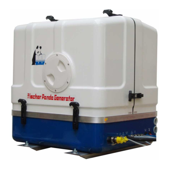
- Page 1 Operation manual Description of the generator and operation manual Marine Generator Panda AGT-DC 5000 PMS Super silent technology 12V - 250A / 4,5kW Fischer Panda GmbH...
-
Page 2: Current Revision Status
Current revision status Document Actual: Panda_AGT-DC_5000_12V_s01285_Operation manual.R03_22.3.11 Replace: Panda_AGT-DC_5000_12V_s01285_Operation manual.R02_17.2.11 Revision Page Updated the whole manual Copyright Duplication and change of the manual is permitted only with consultation with the manufacturer! -
Page 3: Table Of Contents
Table of contents Current revision status ......................2 General References and Regulations ................7 Safety first symbols ......................8 Tools ..........................13 Manufacturer declaration in accordance with the machine guideline 98/37/EG ..15 Customer registration and guarantee ................15 1.4.1 Technical Support ...................... - Page 4 Table of contents 4.3.3 Components of the fuel system ..................42 4.3.4 Components of combustion air ..................44 4.3.5 Components of the electrical system ................. 47 4.3.6 Sensors and switches for operating surveillance ............... 52 4.3.7 Components of the oil circuit ..................... 55 4.3.8 External components ......................
- Page 5 Table of contents Ventilating the fuel system .................... 88 6.3.1 Replace of the fuel filter ..................... 89 6.3.2 Checking the water separator in the fuel supply ............... 90 Replace the air filter ....................... 90 Ventilating of the coolant circuit / freshwater ............. 91 6.5.1 Draining the coolant ......................
- Page 6 11.7.2 The mechanism entrance: ....................142 11.7.3 Terminal connections ....................... 144 11.8 Master-Slave adapter - optional .................. 145 11.8.1 Fischer Panda Art. No. 21.02.02.015H 12V-version ..........145 11.8.2 Fischer Panda Art. No. 21.02.02.01H 24V-version ..........145 11.8.3 Terminal Connections: ..................... 146 11.8.4...
-
Page 7: General References And Regulations
A water-cooled Fischer Panda generator, with the same drive motor, produces 15 % more effective output than the majority of conventional generators. This superiority in efficiency also ensures a fuel saving to the same extent. -
Page 8: Safety First Symbols
General References and Regulations 1.1 Safety first symbols These symbols are used throughout this manual and on labels on the machine itself to warn of the possibility of per- sonal injury. Read these instructions carefully. It is essential that you read the instructions and safety regulations before you attempt to assemble or use unit. - Page 9 General References and Regulations Berühren der entsprechenden Teile und Anlagen verboten Proscription!: Do not touch Generator can be started by an external signal Warning!: Automatic start. These symbols refer to electrical danger and points to special Warning!: High voltage / danger by electricity - warnings, instructions and advices, which must be noticed.
- Page 10 General References and Regulations Warning of materials, which can lead to explosions under Warning!: Risk of explosion certain conditions - e.g. heat or ignition sources Surfaces and substances may be hot. Danger of burn / scal- Warning!: Hot surface ding Warning of materials, which cause corrosive damage during Warning!: Danger carrosive material - contermi- contact.
- Page 11 General References and Regulations Warning!: Hearing damage Warning!: Magnetic field Warning!: High pressure Protective clothing is close fitting, with low resistance to tea- Instruction!: Wear personal protective equip- ring, with narrow sleeves and without protruding parts. It ment (PPE) mainly provides protection against being entangled by moving machine parts.
- Page 12 General References and Regulations Read and consider the regulations, safety instructions and Instruction!: Read the manual instructions installation guidelines of manual, in order to avoid dangers and accidents. You protect yourself and the generator. Environmental protection is the protection of our habitat. For Instruction!: Environmental protection you and your children Seite/Page 12...
-
Page 13: Tools
General References and Regulations Tools This symbols are used throughout this manual to show which tool must be used at maintenance or installation. Spanners SW X = required size X mm Hook wrench for oil filter Screw driver, for slotted head screws and for recessed head screws Multimeter, multimeter with capacitor measuring Socket wrench set Hexagon wrench keys... - Page 14 General References and Regulations Current clamp (DC for synchron generators; AC for asynchron generators) Torque wrench Seite/Page 14 General.R01.1 - Kapitel/Chapter 1: General References and Regulations 22.3.11...
-
Page 15: Manufacturer Declaration In Accordance With The Machine Guideline 98/37/Eg
2. The installation certificate must be despatched within two weeks of use to Fischer Panda. 3. The official guaranty confirmation will be completed by Fischer Panda after receipt and sent to the customer. 4. A guaranty must be shown to make any claims. -
Page 16: Safety Instructions - Safety First
General References and Regulations 1.5 Safety instructions - Safety first! 1.5.1 Safe operation Careful operation is your best assurance against an accident. Read and understand this manual carefully before operating the engine. All operators, no matter how much experience they may have, should read this and other related manuals befor operating the generator or any equipment attached to it. -
Page 17: Safe Handling Of Fuel And Lubricants - Keep Away From Fire
General References and Regulations 1.5.5 Safe handling of fuel and lubricants - Keep away from fire Keep away open fire from fuels and lubricants. Always stop the generator before refueling and/or lubrivating and protect against unintentional starting. Do not smoke or allow flames or sparks in your work area. Fuel is extremely flammable and explo- sive under certain conditions. -
Page 18: Cautions Against Burns And Battery Explosion
Anti-freeze contains poison. Wear rubber gloves to avoid personal injury. In case of contact with skin, whash it off immideately. Do not mix different types of Anti-freeze. The mixture can produce chemical reactioncausing harmful substances. Use approved or genuine Fischer Panda Anti- freeze. -
Page 19: Implementation Of Security And Maintenance
General References and Regulations 1.5.10 Implementation of security and maintenance Disconnect the battery from the generator before conducting service. Put a „DO NOT OPERATE“ tag on the remote control panel to avoid accidental starting. Disconnect any automatic starter device, e.g. battery monitor to prevent automatic starting. To avoid sparks from an accidental short circuit always disconnect the battery´s ground cable (-) first and connect it last. -
Page 20: Protective Grounding And Potential Equalisation
General References and Regulations 1.6.1.1 Protective grounding and potential equalisation In the low voltage board for power supply of the consumers therefore a protective conductor is grounded and connected with electrically conductive objects. The connection with an outer conductor with these object then leads to the earth fault. -
Page 21: Safety Instructions Concerning The Cables
General References and Regulations 1.6.1.4 Safety instructions concerning the cables Cable Type It is recommended is that the cable used be UL 1426 (BC-5W2) compliant, with Type 3 stranding (ABYC Section E- Cable Size The cable size must be selected taking into account the amperage, voltage and conductor length (from the positive power source connection to the electrical device and back to the negative power source connection. -
Page 22: Safety Instructions For The Handling With Batteries
Battery poles must be protected against short circuits by error. Inside the capsule of the Fischer Panda Generator the battery positive line must be protected against heat and vibration by a suitable conduit or sheath and must be routed that way it is not touching any area that will get hot under normal operation like entire engine itself, exhaust elbow and exhaust manifold or exhaust lines or the V-belt and pulleys. - Page 23 The vibrating devices must be regulary checked about scour points and flaw in the isolation. Attention !! For battery charge generators (Fischer Panda AGT-DC)! Check before installation if the battery bank voltage correspond with the generator output voltage 22.3.11...
- Page 24 General References and Regulations Leere Seite / Intentionally blank Seite/Page 24 General.R01.1 - Kapitel/Chapter 1: General References and Regulations 22.3.11...
-
Page 25: Special Notes And Safety Instructions For Agt- Generators
Special notes and safety instructions for AGT- Generators 2. Special notes and safety instructions for AGT- Genera- tors General safety references concerning operation of an AGT generator. Special safety precautions must me made with all energy systems, in order to protect the environment of the com- ponents against fire. - Page 26 Special notes and safety instructions for AGT- Generators A battery must always be connected to the inverter as a capacity! Recommended capacity ≥ - at 240Ah ≥ - at 24V 120Ah The screws at the electric rectifier may be pulled tight only with a torque wrench. Recommend torque: see technical datasheet of the diodes (f.e.
-
Page 27: Measures To The Fire Protection
Special notes and safety instructions for AGT- Generators 2.2.1 Measures to the fire protection. All construction units in the environment of energized parts, which carry more than 50 Amp., must be fire protection- moderately secured. All junction points at the energized parts must be examined regularly on heating up (infrared thermometers). In particular temperature differences are a sign of high transition resistances or bad connections of the warmer con- tact. - Page 28 Special notes and safety instructions for AGT- Generators Leere Seite / Intentionally blank Seite/Page 28 - Kapitel/Chapter 2: Special notes and safety instructions for AGT- Generators 22.3.11...
-
Page 29: In Case Of Emergency First Aid / Im Notfall - Erste Hilfe
In case of Emergency First Aid / Im Notfall - Erste Hilfe 3. In case of Emergency First Aid / Im Notfall - Erste Hilfe First Aid in case of accidends by electrical shocks 5 Safety steps to follow if someone is the victim of electrical shock Do not touch the injured person while the generator is running. -
Page 30: When An Adult Stops Breathing
In case of Emergency First Aid / Im Notfall - Erste Hilfe 3.1 WHEN AN ADULT STOPS BREATHING DO NOT attempt to perform the rescue breathing techniques Warning: provided on this page, unless certified. Performance of these techniques by uncertified personnel could result in further injury or death to the victim. -
Page 31: The Panda Generator
The Panda Generator 4. The Panda Generator Type plate at the Generator Fig. 4.1-1: Type plate at the generator Fig. 4.1-2: Discription type plate 22.3.11 Panda_AGT-DC_5000_12V_s01285_Operation manual.R03 - Chapter 4: The Panda Generator Page 31... -
Page 32: Description Of The Generator
The Panda Generator 4.2 Description of the Generator 4.2.1 Right Side View 10 11 01) Thermostat housing 11) Cooling water return pipe 02) DC-alternator 12V 12) Thermo-switch exhaust 03) V-belt für DC-alternator and cooling water pump 13) Exhaust output 04) Oil pressure switch 14) Exhaust connection port 05) Oil filter 15) Connections for external cooling water expansion tank... -
Page 33: Left Side View
The Panda Generator 4.2.2 Left Side View 21 20 09 10 11 01) Air suction housing with air filter 14) Raw water intake 02) Charge control for DC-alternator 15) Raw water intake hose 03) Air suction port for coil cooling 16) Fuel filter 04) Time relay for stop solenoid 17) Raw water pump... -
Page 34: Front View
The Panda Generator 4.2.3 Front View 11 12 13 01) Ventilation screw internal cooling water pump 15) Cable voltage control VCS (5x1mm²) 02) Stop solenoid 16) Voltage sense 12V 03) Pulley for internal cooling water pump 17) Shunt measurement 04) Raw water intake hose 18) Starter battery minus (-) 05) Raw water pump 19) Starter battery plus (+) -
Page 35: Back View
The Panda Generator 4.2.4 Back View 01) Water-cooled exhaust elbow 08) Sound cover base part 02) Thermo-switch exhaust elbow 09) Heat exchanger 03) Injection port raw water 10) Suction port for coil cooling 04) Generator front cover 11) Electric starter control unit 05) In-flow from external cooling water expansion tank 12) Charge control for DC-alternator 06) Return to external cooling water expansion tank... -
Page 36: Details Of Functional Units
The Panda Generator 4.3 Details of functional units 4.3.1 Components of Cooling System (Raw water) Raw water intake The diagram shows the supply pipes for the generator. The connection neck for the raw water connection is shown on the left hand side. The cross-section of the intake pipe should be nominally larger than the generator connection. - Page 37 The Panda Generator Heat exchanger Separates the raw water system from the freshwater system. Fig. 4.3.1-4: Heat exchanger Ventilation valve A siphon must be installed if the generator sinks below the water line because of the rocking of the boat, even if it is only for a short period of time.
-
Page 38: Components Of Cooling System (Freshwater)
The Panda Generator Exhaust outlet Toghether with the exhaust the raw water gets out here. Fig. 4.3.1-7: Exhaust outlet 4.3.2 Components of Cooling System (Freshwater) Freshwater backflow The cooling water is fed to the heat exchanger from the water-cooled manifold by means of the pipe shown in the dia- gram. - Page 39 The Panda Generator Hose connection pieces for the exter- nal expansion tank The external expansion tank is connected by two hose connections. The connecting pieces shown here serves as constant ventilation for the water-cooling system. In case the external expansion tank is connected with two hoses, the system will ventilate itself.
- Page 40 The Panda Generator Cooling water injection A.) To the thermostat housing B.) From the external expansion tank The intake pipe from the external cooling water expansion tank is connected to the point shown with „B“. Fig. 4.3.2-6: Cooling water injection Internal cooling water pump The diesel motor cooling water pump (see arrow) aids the circulation of the internal...
- Page 41 The Panda Generator Ventilation screw thermostat housing The ventilation screw on the thermostat housing should occasionally be opened for control purposes. Standing machinery should principally carry out ventilating. Fig. 4.3.2-9: Ventilation screw thermostat housing Water-cooled exhaust elbow The manifold is cooled by means of the internal cooling system (freshwater).
-
Page 42: Components Of The Fuel System
The Panda Generator 4.3.3 Components of the fuel system External fuel pump The Panda generator is always supplied with an external, electrical (12 V of DC) fuel pump. The fuel pump must be always installed in the proximity of the tank. The electrical connections with the lead plan- ned for it are before-installed at the gene- rator. - Page 43 The Panda Generator Fuel solenoid valve The fuel solenoid valve opens automati- cally if „START“ is pressed on the remote control panel“. The solenoid closes, if the generator is switched to „OFF“ position. It takes a few seconds before the generator stops.
-
Page 44: Components Of Combustion Air
The Panda Generator Stop solenoid for engine stop Some model are additional equipped with an stop solenoid. The generator is stop- ped by the co-operation of the stop sole- noid immediately after switching off. The adjustment of the stop solenoid must always be checked, in order to be sure that the stop lever can move also during the operation freely and is not under pre-... - Page 45 The Panda Generator Air suction housing Remove the cover to look indes the hou- sing. There is a filter element. This must be checked from timt to time. Fig. 4.3.4-3: Air suction housing Air suction housing with air filter set The figure shows the air filter element in the air suction housing.
- Page 46 The Panda Generator Valve cover Fig. 4.3.4-6: Valve cover Exhaust elbow On the back of the engine is the water- cooled exhaust elbow. On the top side the pipe union for the internal raw water circuit is to be seen and the filler neck for the cooling water.
-
Page 47: Components Of The Electrical System
The Panda Generator Exhaust outlet Connect the exhaust pipe with the water lock. Fig. 4.3.4-9: Exhaust outlet 4.3.5 Components of the electrical system Connection starter battery 1. Cable for starter battery (plus) 2. Cable for starter battery (minus) During the connection to the starter bat- tery it must be always ensured that the contact is perfectly guaranteed. - Page 48 The Panda Generator Electrical connections for control At the front of the generator also all remai- ning cables for the electrical connections are depending upon type. The allocation of the connections result from the plan for the AC-Control box. See here: 1.
- Page 49 The Panda Generator Speed sensor All Panda generators can be equipped with an external automatic start. For the operation of this automatic starting system a separate speed sensor is necessary. At some models the speed sensor is stan- dard installed. Fig.
- Page 50 The Panda Generator Charge control for DC-alternator The voltage regulator for the 12V DC- alternator is on the back of the air suction housing. The housing is formed for coo- ling purposes. The voltage regulator may not be covered from the outside. The sur- face must be accessible for the cooling.
- Page 51 The Panda Generator Fuse for voltage sense F4 1,6A Fig. 4.3.5-12: Fuse for voltage sense Terminal block for remote control cable with fuses and power relais F1 fuse 15A for DC F2 fuse 25A for starter motor Ks relay for starter motor K2 relay for glow plugs K3 relay for fuel pump F1 F2...
-
Page 52: Sensors And Switches For Operating Surveillance
The Panda Generator 4.3.6 Sensors and switches for operating surveillance Thermo-switch at cylinder head The thermo-switch at the cylinder head serves the monitoring of the generator temperature. All thermo-switches for the generators from Panda 6.000 upward are two-pole and laidout as "openers". 110°... - Page 53 The Panda Generator Thermo-switch coil 1. Thermo-switch coil 4x130° C 2. Generator housing 3. Thermo-sensor NTC 981S (for measuring) Fig. 4.3.6-4: Thermo-switch coil Thermo-switch on the (-)- connection Fig. 4.3.6-5: Thermo-switch on the (-)-connection bar Thermo-switch on the (+)-connection Fig. 4.3.6-6: Thermo-switch on the (+)-connection bar 22.3.11 Panda_AGT-DC_5000_12V_s01285_Operation manual.R03 - Chapter 4: The Panda Generator Page 53...
- Page 54 The Panda Generator Thermo-switch on the rectifier block Fig. 4.3.6-7: Thermo-switch on the rectifier block Oil pressure switch In order to be able to monitore the lubrica- ting oil system, an oil pressure switch is built into the system. The oil pressure switch is on the back of the engine (before the electrical starter).
-
Page 55: Components Of The Oil Circuit
The Panda Generator 4.3.7 Components of the oil circuit Oil filler neck with cap Normally the filler neck for the engine oil is on the top side of the valve cover. At numerous generator types a second filler neck is attached additionally at the opera- ting side. -
Page 56: External Components
The Panda Generator Oil drain hose The Panda generator is equipped that the engine oil can be drained over an drain hose. The generator should be always installed therefore that a collecting basin can be set up deeply enough. If this is not possible, an electrical oil drain pump must be installed. -
Page 57: Operation Instructions
The Panda Generator 4.4 Operation Instructions 4.4.1 Daily routine checks before starting 1. Oil level control (ideal level: 2/3 of maximum). AtTTENTION! OIL PRESSURE CONTROL! True, the diesel motor automatically switches off when there is a lack of oil, but it is very damaging for the motor, if the oil level drops to the lowest limit. -
Page 58: Starting Generator - See Remote Control Datasheet
The Panda Generator 4.4.2 Starting Generator - see remote control datasheet 4.4.3 Stopping the Generator - see remote control datasheet 4.4.4 Starting the Generator by a „Failure bypass switch“ There is a "pressure switch" at the terminal block. Faults (e.g. caused by overheating) can be manually overcome by means of this switch. -
Page 59: Installation Instructions
Installation Instructions 5. Installation Instructions 5.1 Placement 5.1.1 Placement and Basemount Since Panda generators have extremely compact dimensions they can be installed in tight locati- ons, attempts are sometimes made to install them in almost inaccessible places. Please consider that even almost maintenance-free machinery must still remain accessible at least at the front (drive belt, water pump) and the service-side (actuator, dipstick). -
Page 60: Generator Connections - Scheme
Installation Instructions 5.2 Generator Connections - Scheme The generator comes supplied with all supply lines (i.e. electric cables, fuel lines etc.) already connected to the motor and generator. The supply lines are fed through the capsule's front base panel and are shielded at the capsule inlets with water-proof grommets. All electrical connections, cable types and sizes must comply to the appropriate regulati- ons. -
Page 61: Cooling System Installation - Raw Water
Installation Instructions 5.3 Cooling System Installation - Raw water 5.3.1 General References The genset should have its own raw water (coolant water) inlet and should not be connected to any other engine systems. Ensure that the following installation instructions are complied with: Avoid galvanic corrosion For the avoidance of galvanic corrosion the chapter "Service instruction for marine gensets (cor- rosion protection)“... -
Page 62: Installation Above Waterline
A repair is then very expensive. Replacement impeller and also a spare pump should always be on board. The old pump can be sent back to Fischer Panda, where it is then economically overhauled completely. 1. Raw water filter 2. Water cock 3. -
Page 63: Installation Below Waterline
Installation Instructions 5.3.5 Installation below waterline If the generator can not be attached at least 600mm over the waterline, a vent valve must be installed into the raw water line. With location beside the "midship line" a possible heeling must be considered! The water hose for the external vent valve at the back of the sound cover splits on the pressure side of the pump and at both ends in each case extended with a connec-... - Page 64 Installation Instructions 1. Generator 2. Ventilation valve Fig. 5.3.5-4: Installation example - ventilation valve Page 64 Panda_AGT-DC_5000_12V_s01285_Operation manual.R03 - Chapter 5: Installation Instructions 22.3.11...
-
Page 65: The Freshwater - Coolant Circuit
Installation Instructions 5.4 The Freshwater - Coolant Circuit 5.4.1 Position of the external Cooling Water Expansion Tank The Panda generator is normally sup- plied with an additional, external cool- ing water expansion tank. This tank must be installed in such a way that its lower edge is at least 500mm more highly arranged than the upper edge of the sound cover. -
Page 66: Ventilation At The First Filling Of The Internal Cooling Water Circuit
Installation Instructions 5.4.2 Ventilation at the first filling of the internal cooling water circuit 1. Fill up the external cooling water expansion tank with coolant. ATTENTION: „maximum fill level = „max.“-mark. The cover of the external expansion tank temporary must be opened. Fig. -
Page 67: Pressure Test For Control Of Cooling Water Circuit
Installation Instructions 4. Start the generator After filling the generator this must be started. During this first phase of start-up, the generator may not be loaded. Switch the generator off after max. 2 minutes of operation! 5. Repeat the steps 1-4 till no air comes out of the vent screw at tthermostat housing. 6. -
Page 68: Watercooled Exhaust System
Installation Instructions Watercooled Exhaust System By injecting the outlet raw water into the exhaust manifold, the exhaust gases are cooled and the noise emissions from the exhaust system are reduced. 5.5.1 Installation of the standard exhaust system The generator exhaust system must remain completely independent and separate from the exhaust system of any other unit(s) on board. -
Page 69: Exhaust / Water Separator
Additionally there is component at Fischer Panda, which exercise both functions of a "exhaust goose neck", and the water separa- tion. With this "exhaust/water separator" the cooling water is derived over a separate pipe. The- reby the exhaust noises at the exterior of the yacht are strongly decreased. -
Page 70: Installation Exhaust/Water Separator
Installation Instructions 5.5.3 Installation exhaust/water separator If the exhaust/water separator was sufficiently highly installed, a goose neck is no longer neces- sary. The exhaust/water separator fulfills the same function. If the "Supersilent" exhaust system were installed correctly, the generator will not disturb your boat neighbour. The exhaust noise should be nearly inaudible. - Page 71 Installation Instructions Example of an unfavorable installation: - water lock not deeply enough under the hights level of the generator - distance water lock to exhaust/water separator too largely Fig. 5.5.3-2: Unfavorable installation - example 22.3.11 Panda_AGT-DC_5000_12V_s01285_Operation manual.R03 - Chapter 5: Installation Instructions Page 71...
-
Page 72: Fuel System Installation
Installation Instructions 5.6 Fuel System Installation 5.6.1 General References Inside the generator capsule itself, there is the fuel filter installed (Exception Panda 4500). Addi- tional fuel filters (with water seperator) must be mounted outside the capsule in easily accessible places in the fuel lines between the tank intake fuel pump and the diesel motor's fuel pump. Generally forward and return fuel flow pipes must be mounted to the diesel tanks. -
Page 73: The Electrical Fuel Pump
Installation Instructions 5.6.2 The electrical fuel pump Electrical fuel pump With the Panda generator is usually supp- lied an external, electrical fuel pump (12V DC). The fuel pump must be installed close at the fuel tank. The electrical con- nections are preloaded at the generator with the lead planned. -
Page 74: Position Of The Pre-Filter With Water Separator
Installation Instructions 5.6.4 Position of the pre-filter with water separator Additionally to the standard fine filter a pre-filter with water separator must be installed outside of the sound cover in the fuel system line. (is not included in deliv- ery.) Fig. - Page 75 Installation Instructions The negative (-) battery cable is connec- ted to the engine foot. Fig. 5.7.1-2: Connection negative battery cable 1. Generator 3. Battery switch 2. Starter battery 12V 4. Fuse Fig. 5.1: Installation starter battery - example 22.3.11 Panda_AGT-DC_5000_12V_s01285_Operation manual.R03 - Chapter 5: Installation Instructions Page 75...
-
Page 76: The Speed Sensor
Installation Instructions 5.7.2 The speed sensor Speed sensor Fig. 5.7.2-1: Speed sensor Installation of the speed sensor The speed sensor tip must have between 0.3 to 0.8mm of clearance (air gap) from the gear tooth tips. In order to achieve this clearance: the speed sensor tip should be aligned with the tip of a gear tooth and screwed in until it touches the tip of the tooth. -
Page 77: Installation Panda Agt12V-System
Installation Instructions 5.7.4 Installation Panda AGT12V-system ATTENTION! Before the electrical system is installed, READ the SAFETY INSTRUCTIONS of this manual FIRST! Be sure that all electrical installations (including all safety systems) comply with all required regulations of the regional authorities. This includes lightnening conductor, personal protection switch etc. - Page 78 Installation Instructions Electrical fuses It is absolutely essential that the electrical system installation is inspected by a qualified electrical technician. The generator should have its own AC input electrical fuses. The fuses should be sized such that the rated current of the generator on each of the individual phases is not excee- ded by more than 25%.
-
Page 79: Voltage Control System
Installation Instructions 5.8 Voltage Control System It is of upmost importance to check the correct functioning of the voltage control system (VCS) during installation or maintenance. Fig. 5.8-1: VCS S1 : CAUTION: The VCS is preset according to the output voltage of the generator. The nominal voltage level of the VCS is imprinted on the top side (S1). -
Page 80: Checking The Vcs Voltage Control Without Requiring The Generator To Run
Installation Instructions Connector 2 Terminal 7 + UM + Battery sense voltage + 12V/24V/36V/48V Terminal 8 - UM - Battery sense voltage Connector 3 Terminal 9 + U(Im) Current sense signal + Max. + 48mV Terminal 10 - U(Im) Current sense signal - 5.8.1 Checking the VCS voltage control without requiring the generator to Prerequisites : 1. -
Page 81: Funktion Of The Vcs
Installation Instructions 5.8.2 Funktion of the VCS The output current of the generator is measured via a shunt with an output voltage of 60mV for the rated current. Factors concerning current measurement: • The generator will shutdown if a cable break in the measurement wire from the shunt to the VCS is detected. -
Page 82: Checking The Current Limit
Installation Instructions 5.8.4 Checking the current limit A DC clamp-meter to monitor the generator output current and a multimeter with a mV DC range are required for this test. The batteries must be discharged prior to testing to ensure that the generator is able to deliver the maximum output. -
Page 83: Battery Monitor
Installation Instructions 5.9 Battery monitor Purpose: Automatic battery voltage monitoring. The generator is started automatically via the remote con- trol panel to start charging when the battery voltage drops below a minimum set level. When the battery voltage exceeds a maximum set level the battery-charging generator is stopped after an interval period which is adjustable Description / Function: Minimum battery voltage level, maximum battery voltage level (when charging is completed) and... - Page 84 Installation Instructions 01. Terminals 1-8 04. Potentiometer switch-on voltage 02. Test switch 05. Potentiometer delay time 03. Potentiometer switch-off voltage Fig. 5.9-1: Battery monitor Page 84 Panda_AGT-DC_5000_12V_s01285_Operation manual.R03 - Chapter 5: Installation Instructions 22.3.11...
-
Page 85: Maintenance Instructions
Maintenance Instructions 6. Maintenance Instructions 6.1 General maintenance instructions 6.1.1 Checks before starting • Oil level • Cooling system leaks • Visual check for any changes, leaks oil drain system, v-belt, cable connections, hose clips, air filter, fuel lines Once a month •... -
Page 86: Execution Of An Oil Change
Maintenance Instructions 6.2.1 Execution of an oil change Oil drain hose Open the passage for the oil drain hose and pull out the hose. Fig. 6.2.1-1: Oil drain hose Oil drain screw The oil can be discharged by opening the oil drain screw. - Page 87 Maintenance Instructions Oil filter change The oil filter can be loosen with an oil filter strap. Fig. 6.2.1-4: Oil filter Oil filter gasket Before the insertation of the new oil filter the gasket should be coated with some- thing oil. Tighten the oil filter only by hand.
-
Page 88: Ventilating The Fuel System
Maintenance Instructions Oil dipstick With the help of the engine oil dipstick the oil level is to examined. The prescribed fil- ling level may not exceed the „Max“ mar- king. We recommend 2/3 oil level. Fig. 6.2.1-7: Oil dipstick 6.3 Ventilating the fuel system Normally, the fuel system is designed to bleed out air itself i.e. -
Page 89: Replace Of The Fuel Filter
Maintenance Instructions 3. After the fuel pump has been running 3 to 4 minutes because the failure bypass switch has been pushed down the ventilation screw of the solenoid valve has to be unscrewed. When ope- ning the screw one has to carry on pushing the switch. -
Page 90: Checking The Water Separator In The Fuel Supply
Maintenance Instructions 6.3.2 Checking the water separator in the fuel supply The pre-filter with water separator has a cock at its lower surface, with this cock the downward sunk water can be discharged. This is simply possible, water is heavier due to its density than the Diesel. -
Page 91: Ventilating Of The Coolant Circuit / Freshwater
Maintenance Instructions 6.5 Ventilating of the coolant circuit / freshwater Special notes for the ventilation of the cooling system If the cooling water is drained or if other air should have arrived into the cooling system, it is necessary to ventilate the cooling system. This ventilation procedure must be repeated several times: ATTENTION ! Before opening the veni- lation points the generator must be... -
Page 92: Draining The Coolant
Maintenance Instructions Open venlation screw at the thermostat housing. Fill in cooling water into the cooling water expansion tank. If it is to be recognized that the cooling water level does not fall anymore, close the filler-cap and the ven- tilation screws and start the generator. -
Page 93: Replace Of The V-Belt For The Internal Cooling Water Pump
Maintenance Instructions Replace of the v-belt for the internal cooling water pump The relative high ambient temperature in the closed sound insulated capsule (about 85° C) can be a reason for a reduced lifespan of the v-belts. It is possible that the "softener" in the rubber com- pound lose their effect after a short operating time because the air in the sound insulated capsule can be relative warm and dry. - Page 94 Maintenance Instructions Press the alternator to the direction of the thermostat housing. Now the v-belt can be changed (type: XPZ 850-2). Fig. 6.6-3: V-belt Stretch the v-belt by pulling the alternator back. The v-belt should be able to be pressing approx. 1cm with the thumb. Tighten the fixing srews above and below the alternator.
-
Page 95: The Raw Water Circuit
Maintenance Instructions 6.7 The raw water circuit 6.7.1 Clean raw water filter The raw water filter should be released regularly from arrears. In each case the water cock must be closed before. It is mostly sufficient to beat the filter punnet. If water should seep through the cover of the raw water filter, this may be sealed in no case with adhesive or sealant. -
Page 96: Replace The Impeller
Maintenance Instructions 6.7.3 Replace the impeller Close the raw water stop cock. Fig. 6.7.3-1: Raw water stop cock Raw water pump on the front side of the genset. Fig. 6.7.3-2: Raw water pump Remove the cover of the raw water pump by loosen the screws from the housing.. - Page 97 Maintenance Instructions Mark the impeller, to make sure that these is used in the correct position at re-instal- lation. Pull to the impeller with a multigrip pliers of the wave. Fig. 6.7.3-4: Impeller Check to the impeller for damage and replace it if necessary.
-
Page 98: Additional Maintenance
Maintenance Instructions 6.8 Additional maintenance Furthermore in addition to the standards checks according to the manual following points of the generator have to be checked: • Automatic shut down of the generator in case off high heating temperature This shall be done by disconnecting the thermo-switch of the heat sink. Next to the rectifier you will find a 2-pole connector. - Page 99 Maintenance Instructions Fig. 6.8-3: Measuring the temperature Ensure, that a fuse next to the battery is installed in the battery line for the generator output cable. Ensure that a battery switch is installed in the battery line. Never leave the generator behind wit- hout the cover mounted over the heat sink and capsule not closed.
-
Page 100: Conservation At Longer Operation Interruption
Maintenance Instructions 6.9 Conservation at longer operation interruption 6.9.1 Measures on preparation of the winter storage 1. Rinse raw water circuit with an anti-freeze solution, even if this contains a corrosion protection means. The raw water inlet must be removed at the water cock. Over a hose connector the anti-freeze protection mixture is to be sucked in from a container. -
Page 101: Initiation At Spring
Start generator and check the basic adjustments of the generator such as voltage, speed re- gulation etc.. • Check all switching off devices for function by operational procedures. Fischer Panda does not take over adhesion for possible damages! 22.3.11 Panda_AGT-DC_5000_12V_s01285_Operation manual.R03 - Chapter 6: Maintenance Instructions Page 101... -
Page 102: Replacing Water Pump
Maintenance Instructions 6.10 Replacing Water pump 1. Drain the freshwater circuit. 2. Unscrew the water pump mounting screws (2), and remove the water pump (1) from the gear case cover. Use a spanner size 10mm. When reassembling • Apply liquid-type gasket (Three Bond 1215 or its equivalent) to both sides of the new water pump gasket. -
Page 103: Replacing Valve Cover Gasket
Maintenance Instructions 6.11 Replacing Valve cover gasket 1. Disconnect the breather hose (1). 2. Remove the cylinder head cover screws (2). 3. Remove the cylinder head cover (3). (When reassembling) • Check to see if the cylinder head cover gasket is not defective. Fig. -
Page 104: Adjustment Of The Valve Clearance
Maintenance Instructions 6.11.1 Adjustment of the valve clearance Valve clearance must be checked and adjusted when engine is cold. 1. Remove the cylinder head cover (1) and the glow plugs. 2. Align the “1TC” mark (2) on the flyw- heel and alignment mark (3) on the rear end plate so that the No. - Page 105 Maintenance Instructions Z482-E2B D662-E2B Z602-E2B D722-E2B D782-E2B D902-E2B Valve arrangement location of piston Number of cylin- Intake valve Exhaust valve Intake valve Exhaust valve No. 1 No. 2 No. 3 X : When No. 1 piston is at the compression top dead center position. O : When No.
- Page 106 Maintenance Instructions Intentionally Blank Page 106 Panda_AGT-DC_5000_12V_s01285_Operation manual.R03 - Chapter 6: Maintenance Instructions 22.3.11...
-
Page 107: Generator Failure
Generator Failure 7. Generator Failure 7.1 Overloading the Generator Please you make sure that the engine is not overloaded. An overloading in the long term can harm the engine. In addition the exhaust gases are soot-blackened (environment). The full rated output of the generator is primarily intended for brief use. As fatigue strength should be calculated in the interest of a long life span of the engine 70% of the nominal load. - Page 108 Generator Failure Is the main supply connection ok? Check polatrity! Does DP+ (VCS ON) lie on clamp 6 of the plug with 6 pins? Fig. 7.2.1-3: Terminal 1-6 on VCS Checking the fuse on the VCS printed cir- cuit board. Fig.
-
Page 109: Fuel Solenoid Valve And Stop Solenoid
Generator Failure 7.2.2 Fuel Solenoid Valve and Stop solenoid For start problems the possibility of an error exists with the solenoid for engine stop or fuel sole- noid valve, which both effect affect simultaneous on the fuel system. 1. Fuel solenoid valve The fuel solenoid valve is located in front of the injection pump. -
Page 110: Dirty Fuel Filter
Generator Failure Stop solenoid for engine stop Fig. 7.2.2-2: Stop solenoid 7.2.3 Dirty fuel filter If the fuel filter is dirty change the filter ele- ment. For replacing the filter element see section 6.3.1, “Replace of the fuel filter” on page 89. 01. -
Page 111: Fuse On Control Panel Board
Generator Failure 7.2.4 Fuse on control panel board It is possible that the fuse on the control circuit board of the control panel is defec- tive. Replace the fuse if it is defective. 01. Fuse on control panel board (630 mA, slow-blow) Fig. -
Page 112: Troubleshooting Table
Generator Failure To prevent such a shut down period the generator can be started in the normal way while pres- sing the Failure bypass button is depressed. This by-passes any faults thus allowing the genera- tor to run. Before pressing the bypass button and starting the generator, a manual check of the engine oil level must be carried out as it is possible that the oil pressure switch caused the generator to cut out. -
Page 113: Tables
Tables 8. Tables Troubleshooting GENERATOR OUTPUT VOLTAGE TOO LOW If the generator delivers less than 12V current ("undervoltage"), there can be various reasons for this: Cause Solution Generator is overloaded. Reduce the electrical load. (Switch off load) Motor is not reaching the rated rpm. Refer to "motor faults"... - Page 114 Tables MOTOR TURNS OVER BUT DOES NOT START Cause Solution Stop solenoid valve not opening. Check wire connections and circuitry to solenoid valve. (ref. DC wiring diagram: Relay K2, Fuse) Fuel pump does not operate. Check fuel-filter and pump: clean if necessary. Lack of fuel.
- Page 115 Tables DROP IN THE SPEED OF THE MOTOR Cause Solution Too much oil. Drain oil. Lack of fuel. Check fuel supply system: - fuel filter, renew if necessary - check fuel pump - check fuel lines (bleed if necessary) Lack of intake air. Check air intake paths.
- Page 116 Tables SOOTY, BLACK EXHAUST Cause Solution Generator is overloaded. Check electrical load and switch off unnecessary load. Insufficient intake air. Check intake air filter; clean if necessary. Fuel injector nozzles faulty. Replace injector nozzles. Valve clearance incorrect. Readjust valve clearance to correct value (refer to Kubota-manual).
-
Page 117: Technical Data Engine
Tables Technical Data Engine Panda AGT 5000 PMS Type Z482 Govenour Cylinder Bore 67mm Stroke 68mm Stroke volume 479cm max. power (SAEJ1349) at 3600 rpm 8,05kW max. bare speed 3800rpm Valve clearance (engine cold) 0,145 - 0,185mm Compression ratio 23:1 Lubrication oil capacity 2,1l ca. - Page 118 Tables Continuous Nominal Nominal power Continuous Nominal voltage Type charging charging [kW] power [kW] [VDC] current[A] current [A] AGT 5000-12 Wiring for vehicle. single phase, not tin-plated, PVC-isolated. allowed conrinuous current (reference point) nominal wire cross-section [mm²] at +30° C [A] at +50°...
-
Page 119: Types Of Coil
Tables Types of Coil HP3 delta-connection Fig. 8.3-1: HP3 delta-connection HP3 star-connection Fig. 8.3-2: HP3 star-connection 22.3.11 Panda_AGT-DC_5000_12V_s01285_Operation manual.R03 - Chapter 8: Tables Page 119... -
Page 120: Inspection Checklist For Services
Tables 8.4 Inspection checklist for services Inspection-Category Durchzuführende Inspektionsarbeiten / Inspection work 100 h prüfen / check erneuern / change Einbauprüfung / Installation check 500 h messen / measure Dichtheit / sealing täglich / daily 1000 h reinigen / clean Isolation prüf. -
Page 121: Engine Oil
Tables Engine oil Engine oil classification Operating range: The operating range of an engine oil is determined by SAE class. "SAE" is for the union of American engineers (Society of Automotives Engineers). The SAE class of an engine oil only informs over the viscosity of the oil (lar- ger number = more viscous, lower number = more highly liquidly) e.g. -
Page 122: Coolant Specifications
Use a mixture of water and antifreeze. The antifreeze needs to be suitable for aluminium. The antifreeze concen- tration must be regularly checked in the interests of safety. Fischer Panda recommend to use the product: GLYSANTIN PROTECT PLUS/G 48. Engine coolant automotive industry Product description Product name GLYSANTIN ®... -
Page 123: Measurements
Tables Measurements Fig. 8.7-1: Measurements 22.3.11 Panda_AGT-DC_5000_12V_s01285_Operation manual.R03 - Chapter 8: Tables Page 123... - Page 124 Tables Intentionally Blank Page 124 Panda_AGT-DC_5000_12V_s01285_Operation manual.R03 - Chapter 8: Tables 22.3.11...
-
Page 125: Generator Control Panel P6
Power - wherever you are Manual Generator Control Panel P6+ 12V version - 21.02.02.046H 24V special version - 21.02.02.047H Option automatic adapter - 21.02.02.016H Option master-slave adapter - 21.02.02.015H Fischer Panda GmbH Panel Generator Control P6+ RE0703_Kunde_eng.R06.1 22.3.11... -
Page 126: Current Revision Status P6+ Manual
Duplication and change of the manual is permitted only in consultation with the manufacturer! Fischer Panda GmbH, 33104 Paderborn, reserves all rights regarding text and graphics. Details are given to the best of our knowledge. No liability is accepted for correctness. Technical modifications for improving the product wit- hout previous notice may be undertaken without notice. -
Page 127: Safety Instructions Generator Control P6
10.1 Personal requirements The settings described here can by performed by the operator, unless otherwise indicated. The installation should be carried out by specially trained personnel or by authorized repair shops (Fischer Panda service points). 10.2 Safety instructions for this chapter Note!: Follow the general safety instruction at the front of this manual. - Page 128 Safety Instructions Generator Control P6+ Note!: Note also the safety of the other components of your system. Seite/Page 128 Panel Generator Control P6+ RE0703_Kunde_eng.R06.1 - Kapitel/Chapter 10: Safety Instructions Generator Control P6+ 22.3.11...
-
Page 129: General Operation
14. Push button panel „off“ 07. LED for battery charge voltage fault green/red 15. Push button panel „on“ Fischer Panda Art. No. 21.02.02.009H LED green: normal operation mode, LED red: fault, LED yellow: warning, LED orange: active 22.3.11 Panel Generator Control P6+ RE0703_Kunde_eng.R06.1 - Kapitel/Chapter 11: General operation... -
Page 130: Rear View 12V-Version
02. Terminal block (master-slave adapter: left row; automatic adapter: right row) 03. Terminals 1-12 (see Kapitel 11.4.2, “Terminal connections,” auf Seite 132) 04. Fuse 630mA slow-blow Fischer Panda Art. No. 21.02.02.009H Seite/Page 130 Panel Generator Control P6+ RE0703_Kunde_eng.R06.1 - Kapitel/Chapter 11: General operation... -
Page 131: Rear View 24V-Version
03. Fuse 630mA slow-blow 04. Terminals 1-12 (see Kapitel 11.4.2, “Terminal connections,” auf Seite 132) 05. Linear controller 24V 06. Linear controller 24V Fischer Panda Art. No. 21.02.02.012H 22.3.11 Panel Generator Control P6+ RE0703_Kunde_eng.R06.1 - Kapitel/Chapter 11: General operation Seite/Page 131... -
Page 132: Installation Of The Remote Control Panel
General operation 11.4 Installation of the remote control panel 11.4.1 Placement. Install the remote control panel at a dry, good accessible and shady place. Connect the remote control panel to the standard 12 core cable at the generator. (1:1) 11.4.2 Terminal connections Standard for NC temperature switch configured i.e. -
Page 133: Function Of The Jumpers
General operation AC-Fault (Fuel Error generator AC input for NC-open-collector-sensor-switch to GND (N = no error). The input ≥ Level) [former T- loads the switch with 2,5mA to +12V. (with 24V-operated internally generated). The occurrence Oil] of an error is delayed, for analysis and displayed, around 100ms. Omission not. The input status is indicated with red LED. - Page 134 General operation J209 DC-Control-Signal (-) = OK dynamo 12V at Kubota Z 482 / D 722 engines DC-Control-Signal (+) = OK three-phase DC-alternator ≥ J210 closed Input AC-Fault has Pull-Up-current 10mA ≥ open Input AC-Fault has Pull-Up-current 2,5mA The solder jumpers are marked on the printed circuit board (with jumper no. and at three-part solder jumper with soldering surface no.) (1): Equivalent resistance for load control lamp e.g.
-
Page 135: Configuration And Adjustment
General operation 11.4.4 Configuration and adjustment 11.4.4.1 Configuration and setting sheet KE01 Standard jumpering for generators with three-phase DC-alternator (Kubota Super 5 series). Panel only for 12V-operation. The safety device is installed with the value 0,63AT. The circuit parts for 24V-operation are not equipped. Fig. -
Page 136: Configuration And Setting Sheet Ke02
General operation 11.4.4.2 Configuration and setting sheet KE02 Standard jumpering for generators with three-phase DC-alternator. Panel for 24V-operation (over attitude of solder jumper J101 alternatively 12V-operation is possible). The safety device is installed with the value 0,63AT. The circuit parts for 24V-operation are not equipped. Fig. -
Page 137: Configuration And Setting Sheet Ke03
General operation 11.4.4.3 Configuration and setting sheet KE03 Standard jumpering for generators with DC-alternator. Panel only for 12V-operation. The safety device is installed with the value 0,63AT. The circuit parts for 24V-operation are not equipped. Fig. 11.4.4.3-1: Einstellung der Lötjumper für diese Konfiguration (Spalte Konf.) Jumper Status Konf. -
Page 138: Configuration And Setting Sheet Ke04
General operation 11.4.4.4 Configuration and setting sheet KE04 Standard jumpering for generators with DC-alternator. Panel for 24V-operation (over attitude of solder jumper J101 alternatively 12V-operation is possible). The safety device is installed with the value 0,63AT. The circuit parts for 24V-operation are not equipped. Fig. -
Page 139: Starting Preparation / Checks (Daily)
General operation 11.5 Starting preparation / Checks (daily) 11.5.1 Marine version 1. Oil level control (ideal level: 2/3 MAX). The level should be about 2/3 of the maximum level of a cold engine. Further, if installed, the oil level of the oil-cooled bearing must be controlled before each start - see sediment bowl at generator front cover!. -
Page 140: Starting And Stopping The Generators
General operation 11.6 Starting and stopping the generators 11.6.1 Starting the generator Warning!: Automatic start Danger for life! - The generator can be equipped with a automa- tik start device. This means the generator can be started by an external signal. To avoid an unexpected starting of the genera- tor, the starter battery must be disconected before start wor- king at the generator. -
Page 141: Stopping The Generator
General operation Attention!: In the event of starting problems, close the sea water inlet cock. Panda marine generators only. Should there be any reason to turn the engine (over) or start the engine i.e. to bleed the fuel system, the sea water inlet cock must be closed! During the starting process, the cooling water pump is driven with the motor. -
Page 142: Automatic Adapter - Optional
01. Main terminals 02. Automatic adapter 21.02.02.016H 03. 8-pole DIP-switch Fischer Panda Art. No. 21.02.02.016H 11.7.1 Function: The automatic adapter RE0704 extends the generator control panel P6+ with an automatic input. A potential-free contact can be attached to this input. If this contact is closed, then the generator, which is attached to the generator control panel P6+, is started automatically. - Page 143 General operation With (+) characterized connection is the input. The input is connected through a resistance to 12V (with 24V-operated internally generated). If the two connections are short circuited over a potential-free contact, then the input current flows. To be considered for an electronic contact the low input current and the polarity is to be selected. The high input current is to be selected for an electromechanical contact.
-
Page 144: Terminal Connections
General operation 11.7.3 Terminal connections Connection for the automatic adapter X2 (row with odd pin numbers // I/O viwe from operating panel) Fig. 11.7.3-1: Terminal connections automatic adapter Pin-no. Pin-name I / O Description power supply + (operation voltage behind fuse) power supply - (ground) VBFS power supply + switched (voltage Pin 1, with panel switched on) -
Page 145: Master-Slave Adapter - Optional
General operation 11.8 Master-Slave adapter - optional 11.8.1 Fischer Panda Art. No. 21.02.02.015H 12V-version Fig. 11.8.1-1: Panel 21.02.02.009H with master-slave adapter 21.02.02.015H 01. Main terminals 02. Master-slave adapter 21.02.02.015H 11.8.2 Fischer Panda Art. No. 21.02.02.01H 24V-version Fig. 11.8.2-1: Panel 21.02.02.012H with master-slave adapter 21.02.02.015H 01. -
Page 146: Terminal Connections
General operation With the Master-Slave-Adapter RE0706 two Generator Control Panels P6+ RE0703 can be connected to a Master- Slave-Combination. In addition on each Generator Control Panel P6+ an Master-Slave-Adapter RE0706 is installed. The Generator Control Panel P6+ is interconnected by the 14pole connecting terminals on the Master-Slave-Adap- ters 1:1. -
Page 147: Terminal X3
General operation LED-AC-Fault Output for LED AC-Fault on the Slave panel, is switched to GND, if the LED is illuminated (Fuel Level) LED-T-Win- Output for LED T-Winding on the Slave panel, is switched to GND, if the LED is illuminated ding DC-Control Output for LED DC-Control-display on the Slave panel. -
Page 148: Configuration And Adjustment
General operation 11.8.6 Configuration and adjustment 11.8.6.1 Configuration and setting sheet KE05 Standard Jumperung for use as Slave-Panel in connection with two Master-Slave-Adapters RE0706 and a Genera- tor Control Panel P6+ RE0703 as Master-Panel. Panel only for 12V-Betrieb. The safety device is installed with the value 0,63AT. The circuit parts for 24V-operation are not equipped. Fig. -
Page 149: Configuration And Setting Sheet Ke06
General operation 11.8.6.2 Configuration and setting sheet KE06 Standard jumpering for use as Slave-Panel in connection with two Maste-Slave-Adapters RE0706 and a Generator Control Panel P6+ RE0703 as Master-Panel. Panel for 24V-operation. (over attitude of solder jumper J101 alterna- tively 12V-operation is possible) The safety device is installed with the value 0,63AT. - Page 150 General operation Seite/Page 150 Panel Generator Control P6+ RE0703_Kunde_eng.R06.1 - Kapitel/Chapter 11: General operation 22.3.11...
-
Page 151: Measurements
Q:\Zeichnungen\7067e01.idw Skizze für Lochbild layout for hole pattern Maßstab: Gewicht: Material: Halbzeug: 21.02.02.009H Artikel Nr.: Otto-Hahn-Str. 32-34 D-33104 Paderborn Tel.: (05254) 9202-0 Fax (05254) 85724 info@fischerpanda.de www.fischerpanda.de Panel Generator Control Datum Name 06.03.2007 jschaefers Bearb. Gepr. Norm. Allgemeintoleranzen nach Blatt 2D Zeichnungs Nr. - Page 152 Measurements Leere Seite / Intentionally blank Seite/Page 152 Panel Generator Control P6+ RE0703_Kunde_eng.R06.1 - 22.3.11...
Need help?
Do you have a question about the Panda AGT-DC 5000 PMS and is the answer not in the manual?
Questions and answers