Table of Contents
Advertisement
Quick Links
Advertisement
Table of Contents
Troubleshooting

Related Manuals for Fischer Panda Panda 14.000 NE PVK-U


Summary of Contents for Fischer Panda Panda 14.000 NE PVK-U
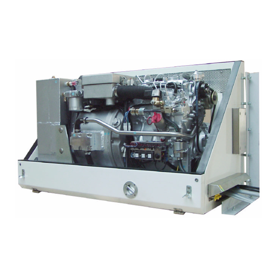
- Page 1 Generator type: Panda 14.000 NE PVK-U 400V - 50 Hz / 12kW Icemaster Fischer Panda...
- Page 2 Icemaster GmbH da generators tors Fischer Panda FISCHER GENERATORS have been manufactured since 1978 and are a well-known brand for first class diesel gene- rators with especially effective sound-insulation. Fischer has been one of the leading manufacturers in respect of quality and know-how during this period.
- Page 3 CALIFORNIA Proposition 65 Warning Diesel engine exhaust and some of its constituents are known to the State of California to cause cancer, birth defects, and other reproductive harm. The electrical Installations may only be carried out be trained and tested personnel! Manufacturer declaration in terms of the machine guideline 98/37/EG .
- Page 4 Safety Instructions The electrical Installations may only be carried out be trained and tested personnel! The generator may not be taken into use with the cover removed. The rotating parts (belt-pulley, belts, etc) must be so covered and protected do that there is no danger to life and body! If a sound insulation covering must be produced at the place of installation, then well-placed signs must show that the generator can only be switched on with a closed capsule.
-
Page 5: Table Of Contents
Table of Contents The Panda Generator ......................3 A.1 Description of the genset ..................... 3 A.1.1 Front View ..........................3 A.1.2 Back View..........................4 A.1.3 Right Side View ......................... 5 A.1.4 View from above........................6 A.2 Detais of functional units ..................... 7 A.2.1 Remote control panel ........................ - Page 6 D.1.9 Checking the Generator Voltage ................... 50 D.1.10 Checking the Capacitors ......................51 D.2 Testing Generator Stator Winding for "Shorts" to Ground ..........53 D.3 Coil Resistance Measurements in Stator Windings ............53 D.3.1 Measuring the Coil Inductive Resistance ................54 D.3.2 Rotor Magnetism Loss and "Re-magnetizing"...
-
Page 7: The Panda Generator
09. Thermostat housing 20. Electrical fuses 10. Pulley for internal cooling water pump and DC-alternator 21. Plug for rpm-sensor 11. Actuator for rpm-regulation 22. Cooling water connection block Panda 14.000 NE PVK-U S00420 - Chapter A: The Panda Generator Page 3... -
Page 8: Back View
09. Oil pressure switch 04. Exhaust output 10. Generator power terminal box 05. Return pipe expansion tank 11. Starter motor 06. DC-Alternator 12. Generator housing with coil Page 4 Panda 14.000 NE PVK-U S00420 - Chapter A: The Panda Generator... -
Page 9: Right Side View
05. Alternative oil filler neck 13. Battery minus (-) 06. Connection fuel in 14. Battery plus (+) 07. Connection fuel out 15. Air suction intake 08. Cable for fuel pump Panda 14.000 NE PVK-U S00420 - Chapter A: The Panda Generator Page 5... -
Page 10: View From Above
12. Air suction housing with air filter 06. DC-alternator 12V 13. Thermo-switch at the silencer 07. De-aerating screw at the thermostat housing 14. De-aerating screw at the silencer Page 6 Panda 14.000 NE PVK-U S00420 - Chapter A: The Panda Generator... -
Page 11: Detais Of Functional Units
(i.e Battery Monitor). A speed gauge and a sensor for speed pick-up are additionally necessary in addition to the automatic start option. (See Component Automatic Start) Panda 14.000 NE PVK-U S00420 - Chapter A: The Panda Generator Page 7... -
Page 12: Components Of Coolant System
Fig. A.3: Cooling water connection block Cooling water pipe From the cooling water connection block the water leads to the internal cooling water pump. Fig. A.4: Coolant flow Page 8 Panda 14.000 NE PVK-U S00420 - Chapter A: The Panda Generator... - Page 13 The de-aerating screw on the thermostat housing should occasionally be opened for control purposes. Standing machinery should principally carry out ventilating. Fig. A.7: De-aerating screw thermostat housing Panda 14.000 NE PVK-U S00420 - Chapter A: The Panda Generator Page 9...
- Page 14 Cooling water pipe Cooling water pipe from the water-cooled exhaust elbow union to the water-cooled pre-silencer. Fig. A.9: Cooling water pipe Watercooled pre-silencer Fig. A.10: Watercooled pre-silencer Page 10 Panda 14.000 NE PVK-U S00420 - Chapter A: The Panda Generator...
- Page 15 Fig. A.12: de-aerating screw Return flow expansion tank The breather pipe at the water-cooled pre- silencer leads to the external expansion tank. Fig. A.13: Return flow Panda 14.000 NE PVK-U S00420 - Chapter A: The Panda Generator Page 11...
-
Page 16: Components Of Fuel System
In all cases a further pre-filter with water separator must be installed. See directions for fuel filter instal- lation. Fig. A.16: Fuel filter Page 12 Panda 14.000 NE PVK-U S00420 - Chapter A: The Panda Generator... - Page 17 2) Ventilation screw solenoid valve 3) Magnetic coil Fig. A.17: Fuel solenoid valve Injection nozzles Fig. A.18: Injection nozzles Glow plugs Glow plugs heat the pre-chamber up Fig. A.19: Glow plugs Panda 14.000 NE PVK-U S00420 - Chapter A: The Panda Generator Page 13...
-
Page 18: Components Of Combustion Air
The air suction housing sucks in fresh air from the sound cover. Fig. A.21: Air suction housing Air suction housing with air filter Fig. A.22: Air filter Page 14 Panda 14.000 NE PVK-U S00420 - Chapter A: The Panda Generator... - Page 19 Watercooled exhaust manifold Fig. A.24: Watercooled exhaust manifold Compensator under heat isolation This part is flexible by the internal struc- ture and compensates vibrations. Fig. A.25: Compensator Panda 14.000 NE PVK-U S00420 - Chapter A: The Panda Generator Page 15...
-
Page 20: Components Of Electrical System
Connection starter battery 1. Cable for starter battery (minus) 2. Cable for starter battery (plus) Fig. A.27: Cable for starter battery Connection for load Fig. A.28: Connection for load Page 16 Panda 14.000 NE PVK-U S00420 - Chapter A: The Panda Generator... - Page 21 Actuator for rpm-regulation The generator voltage is determined by progressive speed control through "VCS" in conjunction with the speed actuator. Speed increases with increasing load. Fig. A.31: Actuator Panda 14.000 NE PVK-U S00420 - Chapter A: The Panda Generator Page 17...
- Page 22 Fig. A.32: DC-alternator Charge control for DC-alternator Fig. A.33: Charge control Generator power terminal box L1 L2 L3 Fig. A.34: Generator power terminal box Page 18 Panda 14.000 NE PVK-U S00420 - Chapter A: The Panda Generator...
-
Page 23: Sensors And Switches For Operating Surveillance
A.2.6 Sensors and switches for operating surveillance Thermo-switch at cylinder head Fig. A.36: Thermo-switch at cylinder head Thermo-switch at watercooled exhaust manifold Fig. A.37: Thermo-switch at exhaust manifold Panda 14.000 NE PVK-U S00420 - Chapter A: The Panda Generator Page 19... - Page 24 Fig. A.38: Thermo-switch at silencer Thermo-switch at the generator coil 1. Generator coil 2. Thermo-switch 3. Housing Fig. A.39: Thermo-switch Oil pressure switch at engine Fig. A.40: Oil pressure switch Page 20 Panda 14.000 NE PVK-U S00420 - Chapter A: The Panda Generator...
-
Page 25: Components Of Oil Curcuit
Engine oil filler neck with cap Alternative engine oil filler neck to mainte- nance work. See details of oil specification. Fig. A.43: Engine oil filler neck with cap Panda 14.000 NE PVK-U S00420 - Chapter A: The Panda Generator Page 21... - Page 26 The screw on this hose must be opened when changing the oil. Fig. A.46: Engine oil drain hose Page 22 Panda 14.000 NE PVK-U S00420 - Chapter A: The Panda Generator...
-
Page 27: Ecternal Components
Since the suction height and the supply pressure are limited, it can be sometimes possible that for reinforcement a second pump must be installed. Fig. A.49: Electrical fuel pump Panda 14.000 NE PVK-U S00420 - Chapter A: The Panda Generator Page 23... - Page 28 The Panda Generator Page 24 Panda 14.000 NE PVK-U S00420 - Chapter A: The Panda Generator...
-
Page 29: Generator Operating Instructions
For safety however, the capacitors have to be discharged (short circuited) prior to carrying out any work on the AC-Control box. CAUTION! Do not touch the capacitor contact terminals! Panda 14.000 NE PVK-U S00420 - Chapter B: Generator Operating Instructions Page 25... -
Page 30: Operating Instructions
It is important that every person who operates the generator is informed of this situation. This is practically the only handling error that can be made on board that can lead to fatal consequences for both generator and operator. Page 26 Panda 14.000 NE PVK-U S00420 - Chapter B: Generator Operating Instructions... - Page 31 Tips regarding Starter Battery Fischer Panda recommends normal starter battery use. If an genset is required for extreme win- ter conditions, then the starter battery capacity should be doubled. It is recommended that the starter battery be regularly charged by a suitable battery-charging device (i.e., at least every 2...
-
Page 32: B.2.3Overloading Of Engine During Longer Operation
(For temperatures below - 8°C check whether there is winter fuel) 7. Check circuit- voltmeter, to test whether there is AC voltage and is within the tolerance range (Frequency and voltage). Page 28 Panda 14.000 NE PVK-U S00420 - Chapter B: Generator Operating Instructions... -
Page 33: B.2.5Stopping The Generator
(or even no voltage) since the stator windings do not have the chance to reach full excitation. Electrical units which are switched on in this condition could possibly be damaged (special caution should be practised with electric motors to avoid burnout). Panda 14.000 NE PVK-U S00420 - Chapter B: Generator Operating Instructions Page 29... -
Page 34: B.2.7Operating Control System On The Panda Generator
4. Thermo-switch in the genset coil 5. Oil pressure switch Thermo-switch at watercooled exhaust silencer Fig. B.1: Thermo-switch watercooled exhaust silencer Thermo-switch at cylinder head Fig. B.2: Thermo-switch cylinder head Page 30 Panda 14.000 NE PVK-U S00420 - Chapter B: Generator Operating Instructions... - Page 35 Thermo-switch at silencer Fig. B.3: Thermo-switch silencer Thermo-switch at coil 01. Thermo-switch coil 160°C 02. Generator housing Fig. B.4: Thermo-switch coil Oil pressure switch Fig. B.5: Oil pressure switch Panda 14.000 NE PVK-U S00420 - Chapter B: Generator Operating Instructions Page 31...
- Page 36 Generator Operating Instructions Page 32 Panda 14.000 NE PVK-U S00420 - Chapter B: Generator Operating Instructions...
-
Page 37: Maintenance Instructions
An oil drainage hose is fitted in the sound cover for changing the oil. This is fed through the capsule to the outside. Open the pass-through cover at the sound cover for the oil drain hose. Panda 14.000 NE PVK-U S00420 - Chapter C: Maintenance Instructions Page 33... - Page 38 The oil drainage screw is then closed again and the hose again stored in the sound-insulated capsule. The oil filter could be loosen by a tool (oil- filter strap) Page 34 Panda 14.000 NE PVK-U S00420 - Chapter C: Maintenance Instructions...
- Page 39 The new oil is filled here. With the help of the engine oil dipstick the oil level is too examined. The prescribed filling level may not exceed the „Max“ mar- king. Panda 14.000 NE PVK-U S00420 - Chapter C: Maintenance Instructions Page 35...
-
Page 40: De-Aerating Of The Coolant Circuit
The de-aerating process has to be rerun- ned several times. Open de-aerating screw at the cooling water pump. Open de-aerating screw at the thermostat- houing Open de-aerating screw at the watercoo- led silencer. Page 36 Panda 14.000 NE PVK-U S00420 - Chapter C: Maintenance Instructions... - Page 41 Please wait until the temperatures raise more and check if the fan will activate. It makes sense to, once again, repeat the de-aerating procedure after a few days, in order to ensure that remaining air bubbles have been finally removed. Panda 14.000 NE PVK-U S00420 - Chapter C: Maintenance Instructions Page 37...
-
Page 42: Air-Bleeding Of The Fuel System
Try again to start the unit. After the unit has started the pipe union nut has to be tightened again. Page 38 Panda 14.000 NE PVK-U S00420 - Chapter C: Maintenance Instructions... -
Page 43: Exchange Of The Fuel Filter
The arrow on the filter housing indicates the direction of the fuel flow. A clogged filter causes a decreased power output of the generator Panda 14.000 NE PVK-U S00420 - Chapter C: Maintenance Instructions Page 39... -
Page 44: Exchange The Air Filter
Open the combustion air housing by loo- sen the clamp at the cover. Loose the wing bolt and lift the frame that holds the air filter. Change the air filter (MANN C2039). Page 40 Panda 14.000 NE PVK-U S00420 - Chapter C: Maintenance Instructions... -
Page 45: Exchange Of The V-Belt
We suggest to stand by the according service-packet. Loosen the fixing screw above the alter- nator. Loosen the fixing screw below the alterna- tor only a little bit. Panda 14.000 NE PVK-U S00420 - Chapter C: Maintenance Instructions Page 41... - Page 46 Stretch the v-belt by pulling the alternator back. The v-belt should be able to be pressing approx. 1cm with the thumb. Tighten the fixing srews above and below the alternator. Page 42 Panda 14.000 NE PVK-U S00420 - Chapter C: Maintenance Instructions...
-
Page 47: Generator Failure
100% if it is properly designed. If the inductive load (i.e. E-Motor) is more than 20% of the generator nominal power, a compensation is necessary. See also the information brochure "Special information for operation of Panda generators with inductive load". Panda 14.000 NE PVK-U S00420 - Chapter D: Generator Failure Page 43... -
Page 48: D.1.1Generator Voltage Fluctuations And Monitoring
With an adjusting screw directly at the base of the rev regulator lever. (only up) After all work at the components of the rev regulation is done the adjustment of the limitation must be checked. Page 44 Panda 14.000 NE PVK-U S00420 - Chapter D: Generator Failure... -
Page 49: D.1.4Adjustment Of The Maximum Upper Revolution
5V above the normal operating border. 01. Adjusting screw upper keystroke 02. Countering nut 03. Rev regulator lever This adjustment should not be chan- ged, otherwise the warranty expires. Panda 14.000 NE PVK-U S00420 - Chapter D: Generator Failure Page 45... -
Page 50: D.1.5Adjustment Of The Normal Rev Limitation
If the adjustment is finished the plug of the actuator must be re-connect for operation. Re-connect the connections if the electrical supply lines in the AC-control box were also be dis- connected. Page 46 Panda 14.000 NE PVK-U S00420 - Chapter D: Generator Failure... -
Page 51: D.1.6Lubrication Of The Spiral Thread Spindle
Check the electrical fuse (miniature slow-to-blow fuse 1,6A) on the control printed circuit board if the actuator will not turn at all. Change fuse here (1,6A slow to blow) Panda 14.000 NE PVK-U S00420 - Chapter D: Generator Failure Page 47... - Page 52 4. If the motor react on the turn by manual strongly (the motor can normally hold with the fingers) the drive will be working faultless. If there are nevertheless faults in the voltage control there is a fault in the control VCS. Page 48 Panda 14.000 NE PVK-U S00420 - Chapter D: Generator Failure...
-
Page 53: D.1.8Low Generator Output Voltage
If the generator does not produce any voltage while the diesel drive engine is running, the suspected cause lies outside the generator capsule. - electrical load not switched off prior to start - short circuit somewhere in electrical system - electrical overload Panda 14.000 NE PVK-U S00420 - Chapter D: Generator Failure Page 49... -
Page 54: D.1.9Checking The Generator Voltage
An unusually warm capacitor is also a sign that it is faulty or near the end of its life span. Page 50 Panda 14.000 NE PVK-U S00420 - Chapter D: Generator Failure... -
Page 55: D.1.10Checking The Capacitors
"beeps" when the selector is set to continuity and the end probes are contacted together. Checking Switch the multimeter to „Continuity: acou- stic signal“ and touch both capacitor termi- nals with the meter end probes. Panda 14.000 NE PVK-U S00420 - Chapter D: Generator Failure Page 51... - Page 56 This can lead to faster deterioration of the capacitors. ATTENTION! Do not contact the capacitor. Before working on the System read the Section "Safety instructions" in this Manual. AC Output Terminal box 230V/400V-50Hz Page 52 Panda 14.000 NE PVK-U S00420 - Chapter D: Generator Failure...
-
Page 57: Testing Generator Stator Winding For "Shorts" To Ground
To measure coil resistance a meter capable of measuring low resistances (Milli-Ohm resolution if possible) accurately. The measured resistance values should be close to the same between the following terminals: L1-N, L2-N, L3-N. Panda 14.000 NE PVK-U S00420 - Chapter D: Generator Failure Page 53... -
Page 58: Measuring The Coil Inductive Resistance
MEGA-meter with a high test voltage If you find any anormality, when doing this test, please ask your Fischer Panda dealer. If the measured resistance values deviate from each other significantly, then there is probably a short within the coils. -
Page 59: D.3.2Rotor Magnetism Loss And "Re-Magnetizing
(otherwise, it is very DANGEROUS TO LIFE!) Initializing the magnetic field in the windings through exter- nal current from a 4,5 - 9 volt battery. (No car-battery !) Panda 14.000 NE PVK-U S00420 - Chapter D: Generator Failure Page 55... -
Page 60: Starting Problems
"react immediately" by revving high.If the motor does not react sharply to the recon- nection of the solenoid wire, it is a sign that the solenoid valve could be faulty. 01. Fuel solenoid valve 02. Fuel injector line 03. Ventilation screw Page 56 Panda 14.000 NE PVK-U S00420 - Chapter D: Generator Failure... -
Page 61: Failure Bypass Switch
Should the overheating alarm be set off, caused by heat accumulation, after the generator has been switched off, then this can also be bypassed using the switch. D.5 Troubleshooting Table Table F.4, “Troubleshooting,” on Page IV For Troubleshooting see Panda 14.000 NE PVK-U S00420 - Chapter D: Generator Failure Page 57... - Page 62 Generator Failure Page 58 Panda 14.000 NE PVK-U S00420 - Chapter D: Generator Failure...
-
Page 63: Installation Instructions
07. Cable for AC-Control box 03. Cable for fuel pump 08. Battery minus (-) 04. Cable for remote control panel 09. Battery plus (+) 05. Cable for VCS Panda 14.000 NE PVK-U S00420 - Chapter E: Installation Instructions Page 59... -
Page 64: Fuel System Installation
The external electrical fuel pump is to be installed in the proximity of the tank. Anschluß des Kraftstoffsystems 1. Generator 4. External fuel filter 2. Non-return valve 5. Fuel tank 3. External fuel pump Page 60 Panda 14.000 NE PVK-U S00420 - Chapter E: Installation Instructions... -
Page 65: Connection To 12V Starter Battery-Block
To avoid large voltage drops the battery should be installed as near as possible to the generator. The positive terminal of the battery is attached at the red cable, the negative pole at the blue cable. 1. Generator 2. Battery block 12V Panda 14.000 NE PVK-U S00420 - Chapter E: Installation Instructions Page 61... -
Page 66: Connection Of Electrical Components
Installation Instructions E.1.5 Connection of electrical components Connection of electrical components 1. Generator 3. Remote control panel 2. External fuel pump 4. AC-Control box Page 62 Panda 14.000 NE PVK-U S00420 - Chapter E: Installation Instructions... -
Page 67: Connection Of The External Radiator
Installation Instructions E.1.6 Connection of the external radiator Connection of the external radiator 1. Generator 2. External radiator Panda 14.000 NE PVK-U S00420 - Chapter E: Installation Instructions Page 63... -
Page 68: Ac-Control Box
The front panel must always be closed, since the AC-Control box produces 400V during operation. 1. Terminal block for excitation cable 3. Excitation capacitors (6x60µF) 2. VCS-printed board 5. Booster capacitor (3x40µF) Page 64 Panda 14.000 NE PVK-U S00420 - Chapter E: Installation Instructions... -
Page 69: Voltage Control System
5. Electrical fuse (1,6A slow to blow) 2. Adjustment booster voltage (do not adjust!) 6. Potentiometer for booster time 3. Adjustment VCS-voltage 7. Connection for PC 4. Connection VCS inlet Panda 14.000 NE PVK-U S00420 - Chapter E: Installation Instructions Page 65... -
Page 70: The Fan Control
The solder bridge J1 is located directly behind the circuit board fuse when viewed from the main connection. Fan control 01. Connection „Battery (+)“ 04. Terminal 9 02. Terminal 7 05. Internal fuse 03. Terminal 8 06. Solder bridge J1 Page 66 Panda 14.000 NE PVK-U S00420 - Chapter E: Installation Instructions... -
Page 71: Cooling System
Additional ventilators may be necessary should the warm air need to be channelled through pipes. It must be ensured that warm air is extracted out of the radiator. Panda 14.000 NE PVK-U S00420 - Chapter E: Installation Instructions Page 67... - Page 72 The radiator can be installed (vertically) or (horizontally). Consideration must be given to the fact that air is drawn in via a fan motor. The best result is achieved if the radiator is fitted vertically on the vehicle roof. Page 68 Panda 14.000 NE PVK-U S00420 - Chapter E: Installation Instructions...
- Page 73 4mm). Because water can enter the fan (rainwater, condenswater, sweatwater etc.). The water can run out through these holes. (see below 02) Generally a fan is a wearing part and should be changed one time a year. Panda 14.000 NE PVK-U S00420 - Chapter E: Installation Instructions Page 69...
- Page 74 The coolant expansion tank is not normally supplied by ICEMASTER. For this a standard vehicle expansion tank is the most suitable. Vehicle accessory range is the most suitable. Page 70 Panda 14.000 NE PVK-U S00420 - Chapter E: Installation Instructions...
- Page 75 This coolant impeller pump is mounted on the generator as an additional pump, and is driven by pulleys. The pump action is carried out by a "rubber impeller". Panda 14.000 NE PVK-U S00420 - Chapter E: Installation Instructions Page 71...
- Page 76 They are also valid for operation at high temperatures. During constant duty at normal temperatures (20°C), the values should be well below the above named data. Page 72 Panda 14.000 NE PVK-U S00420 - Chapter E: Installation Instructions...
- Page 77 The manufacturer should be consulted in cases of doubt. The generator can be fitted to the vehicle cooling system via a heat exchanger, should there be any objections. Panda 14.000 NE PVK-U S00420 - Chapter E: Installation Instructions Page 73...
- Page 78 ICEMASTER will not accept any liability, if further units (i.e. vehicle motor) are damaged, when a part of the generator cooling system itself breaks down. Page 74 Panda 14.000 NE PVK-U S00420 - Chapter E: Installation Instructions...
- Page 79 Decisive for the success of this procedure is that sufficient water enters to internal coolant pump, so that the coolant pump can function. The coolant pump cannot draw water as long as there is air in the casing. Panda 14.000 NE PVK-U S00420 - Chapter E: Installation Instructions Page 75...
- Page 80 02. Coolant expansion tank 08. Thermoswitch 03. Ventilation pipe 09. Bucket with submerged pump 04. Ventilation screw 10. Water-cooled pre-silencer 05. Fan for radiator 11. Internal cooling water pump 06. Radiator Page 76 Panda 14.000 NE PVK-U S00420 - Chapter E: Installation Instructions...
- Page 81 10. Pipe with connection for Thermoswitch 04. External fan control 11. Radiator 05. Dry silencer 12. Fan for radiator 06. Exhaust outlet 13. Bucket with submerged pump 07. Pipe with connection for Thermoswitch Panda 14.000 NE PVK-U S00420 - Chapter E: Installation Instructions Page 77...
- Page 82 Installation diagram for radiator on the roof 1. Ventilation pipe 4. T-piece for Ventilation pipe 2. Radiator (horizontal) 5. External cooling water pump 3. Coolant expansion tank (integrated) 6. Bucket with submerged pump Page 78 Panda 14.000 NE PVK-U S00420 - Chapter E: Installation Instructions...
- Page 83 Installation diagram with special air separator 1. Ventilation pipe 5. Exhaust output 2. Coolant expansion tank 6. Special air separartor 3. T-piece for coolant expabsion tank 7. Radiator 4. Water-cooled pre-silencer Panda 14.000 NE PVK-U S00420 - Chapter E: Installation Instructions Page 79...
-
Page 84: Exhaust Installation
Exhaust connection for mounting below the vehicle 1. Generator 5. Vibration damper 2. Exhaust outlet 6. Exhaust pipe 3. Compensator 7. External series silencer 4. External pre-silencer 8. End pipe Page 80 Panda 14.000 NE PVK-U S00420 - Chapter E: Installation Instructions... -
Page 85: Appendix
Engine speed (rpm) or frequency (Hz) Change of the fuel filter Change of the air filter Cooler fan under load at bridged temperature sensor/ temperature switch Uptake of the ambient temperature Panda 14.000 NE PVK-U S00420 - Chapter F: Appendix Page I... -
Page 86: Engine Oil
API CG Engine oil for highest demands, turbo-tested Engine oil types above 25°C SAE30 or SAE10W-30 SAE10W-40 0°C to 25°C SAE20 or SAE10W-30 SAE10W-40 below 0°C SAE10W or SAE10W-30 SAE10W-40 Page II Panda 14.000 NE PVK-U S00420 - Chapter F: Appendix... -
Page 87: Coolant Specifications
Water content DIN 51 777 part 1 max. 3,5 % pH-value undiluted 7,1 – 7,3 Coolant mixture ratio Water/antifreeze Temperature 70:30 -20°C 65:35 -25°C 60:40 -30°C 55:45 -35°C 50:50 -40°C Panda 14.000 NE PVK-U S00420 - Chapter F: Appendix Page III... -
Page 88: Troubleshooting
"Easy Start Booster Set". (See App. G) Enquire at your nearest Panda dealer or directly at the manufacturer. Page IV Panda 14.000 NE PVK-U S00420 - Chapter F: Appendix... - Page 89 5. Determine cause for excess water in the combustion chamber. The excess water can be caused by a defective air vent in the cooling water system, which should be checked and cleaned, or replaced if faulty. Panda 14.000 NE PVK-U S00420 - Chapter F: Appendix Page V...
- Page 90 Lack of oil (oil pressure sensor tripped). Is indicated on Check oil-level and if necessary top up. the remote control panel. Check motor's oil-pressure and have repaired by Kubota-Service if necessary. Page VI Panda 14.000 NE PVK-U S00420 - Chapter F: Appendix...
- Page 91 1. Loosen the connecting rods motor from the injection pump regulator and turn screw to a max. voltage of 240V. 2. Loosen the connecting plugs of the Motor VCS electronic and turn the motor direct by hand. Panda 14.000 NE PVK-U S00420 - Chapter F: Appendix Page VII...
- Page 92 Appendix Page VIII Panda 14.000 NE PVK-U S00420 - Chapter F: Appendix...
-
Page 93: Technical Data Engine
12 kW , 3000mtr alt., 50°C Output voltage 400 V Output current 30 A Frequency 50 Hz Stator Da 300 mm Stator Di 170 mm Rotor Lfe 120 mm Panda 14.000 NE PVK-U S00420 - Chapter F: Appendix Page IX... -
Page 94: Measurements
Measurements F.7 Measurements Page X Panda 14.000 NE PVK-U S00420 - Chapter F: Appendix... -
Page 95: Wiring Diagram Control Panel
Wiring diagram control panel F.8 Wiring diagram control panel Panda 14.000 NE PVK-U S00420 - Chapter F: Appendix Page XI... - Page 96 Wiring diagram control panel Page XII Panda 14.000 NE PVK-U S00420 - Chapter F: Appendix...
- Page 97 5 Safety steps to follow if someone is the victim of electrical shock Do not try to pull or grab the individual. If you cannot turn off the electrical power, pull, push, or lift the person to safety using a wooden pole, rope, or some nonconductive material.
- Page 98 WHEN AN ADULT STOPS BREATHING WARNING DO NOT attempt to perform the rescue breathing techniques provided on this page, unless certified. Perfor- mance of these techniques by uncertified personnel could result in further injury or death to the victim. Does the Person Respond? Shout, "Help!"...
Need help?
Do you have a question about the Panda 14.000 NE PVK-U and is the answer not in the manual?
Questions and answers