
Related Manuals for Fischer Panda 45i pms


Summary of Contents for Fischer Panda 45i pms
-
Page 1: Manual Panda 45I Pms
Manual Panda 45i PMS Super silent technology 400 V 50 Hz 45 kVA Fischer Panda GmbH Panda_45i_PMS_System_eng.R02 8.10.14... -
Page 2: Current Revision Status
Duplication and change of the manual is permitted only in consultation with the manufacturer! Fischer Panda GmbH, 33104 Paderborn, reserves all rights regarding text and graphics. Details are given to the best of our knowledge. No liability is accepted for correctness. Technical modifications for improving the product wit- hout previous notice may be undertaken without notice. - Page 3 8.10.14 Kapitel/Chapter A: - Seite/Page 3...
- Page 4 Seite/Page 4 - Kaptitel/Chapter A: 8.10.14...
-
Page 5: Table Of Contents
3.5.1 Bolted Fischer Panda transport box ................... 33 3.5.2 Fischer Panda transport box with metal tab closure ............33 Opening the MPL sound insulation capsule ..................34 3.6.1 Opening the GFK sound insulation capsule ............... 35 Transport and Loading/Unloading .................... -
Page 6: Measures For Removing Surface Protection After Medium Term Downtimes
Protection conductor: ......................55 5.3.5 Operating control system on the Fischer Panda generator ..........55 Instructions for capacitors - not present at all models................. 55 Checks before start - see remote control panel data sheet ..............55 Starting the generator - see remote control panel data sheet............ - Page 7 Installation of the cooling system - raw water ..................61 6.4.1 General information ......................61 6.4.2 Fischer Panda installation kit - raw water ................61 6.4.3 Installation of the through hull fitting in Yachts - scheme ........... 63 6.4.4 Quality of the raw water sucking in line ................
- Page 8 Inhalt / Contens Personal requirements ........................97 Hazard notes for the maintenance ...................... 97 Environmental protection ........................99 Maintenance Requirements ........................ 99 Maintenance interval ........................... 99 7.5.1 Check of hoses and rubber parts in the sound insulated capsule ........99 Checking oil-level ..........................
- Page 9 Inhalt / Contens Personal requirements........................143 Safety instructions for this chapter....................143 Tools and measuring instruments..................... 144 Overloading the generator ........................ 145 8.4.1 Low generator-output voltage .................... 146 Starting problems..........................146 8.5.1 Fuel solenoid valve ......................146 8.5.2 Dirty fuel filter ........................
- Page 10 Terminal assignments on the Panda iControl2 controller ..........202 3.4.1.1 Terminal assignment of 18-pin connector ............202 3.4.1.2 Fischer Panda standard bus ................202 3.4.1.3 Fischer Panda CAN bus..................202 Start-up ............................. 203 Seite/Page 10 Kapitel/Chapter 1: 8.10.14...
- Page 11 4 Maintenance ............................... 205 Maintenance of the iControl2 controller .................... 205 4.1.1 Cleaning the iControl2 controller ..................205 Maintenance of the iControl2 remote control panel ................205 4.2.1 Cleaning the iControl2 controller ..................205 5 Warnings and error messages ......................... 207 Warnings............................
- Page 12 Seite/Page 12 - Kaptitel/Chapter 1: 8.10.14...
- Page 13 Not only do you have a Fischer Panda generator on board, you also have worldwide support from the Fischer Panda Team. Please take the time to read this and find how we can support you further.
-
Page 14: General Instructions And Regulations
General Instructions and Regulations 1. General Instructions and Regulations 1.1 Safety first! These symbols are used throughout this manual and on labels on the machine itself to warn of the possibility of personal injury of lethal danger during certain maintenance work or operations. Read these instructions carefully. Can cause acute or chronic health impairments or death WARNING: Hazardous materials even in very small quantities if inhaled, swallowed, or... - Page 15 General Instructions and Regulations Touching of the corresponding parts and systems is PROHIBITED: Do not touch prohibited. Danger for life! Working at a running generator can DANGER: Automatic start-up result in severe personal injury. The generator can be equipped with a automatic start device. This means, an external signal may trigger an automatic start-up.
- Page 16 General Instructions and Regulations Warning of substances that may cause an explosion under WARNING: Explosion hazard certain conditions, e.g. presence of heat or ignition sources. Warning of hot surfaces and liquids. Burn/scalding hazard. WARNING: Hot surface Warning of substances that cause chemical burns upon WARNING: Danger due to corrosive substances, contact.
- Page 17 General Instructions and Regulations Wearing the applicable snugly fitting protective clothing MANDATORY INSTRUCTION: Wear snugly fitting provides protection from hazards and can prevent damage to protective clothing (PPE). your health. Wearing hearing protection provides protection from acute MANDATORY INSTRUCTION: Wear hearing and gradual hearing loss.
-
Page 18: Tools
General Instructions and Regulations 1.2 Tools These symbols are used throughout this manual to show which tool must be used for maintenance or installation. Spanners W.A.F X = width across flats of X mm Hook wrench for oil filter Screw driver, for slotted head screws and for Phillips head screws Multimeter, multimeter with capacitor measuring unit Socket wrench set Hexagon socket wrench set... - Page 19 General Instructions and Regulations Clamp-on ammeter (DC for synchronous generators; AC for asynchronous generators) Torque wrench 8.10.14 Kapitel/Chapter 1: General Instructions and Regulations - Seite/Page 19...
-
Page 20: Manufacturer Declaration In Accordance With The Machinery Directive 2006/42/Ec
• You will receive free upgrades as necessary. Additional advantages: Based on your complete data record, Fischer Panda technicians can provide you with fast assistance, since 90 % of the disturbances result from defects in the periphery. Problems due to installation errors can be recognized in advance. -
Page 21: Safety Instructions - Safety First
General Instructions and Regulations 1.5 Safety Instructions - Safety First! 1.5.1 Safe operation Careful handling of the equipment is the best insurance against an accident. Read the manual diligently, and make sure you understand it before starting up the equipment. All operators, regardless of their experience level, shall read this manual and additional pertinent manuals before commissioning the equipment or installing an attachment. -
Page 22: Safe Handling Of Fuels And Lubricants
General Instructions and Regulations 1.5.5 Safe handling of fuels and lubricants Keep fuels and lubricants away from naked fire. Before filling up the tank and/or applying lubricant, always shut down the generator and secure it against accidental start-up. Do not smoke and avoid naked flame and sparking near fuels and the generator. Fuel is highly flammable and may explode under certain conditions. -
Page 23: Safety Precautions Against Burns And Battery Explosions
Do not mix different anti-freeze agents. The mixture may cause a chemical reaction generating harmful substances. Use only anti-freeze that was approved by Fischer Panda. Protect the environment. Collect drained fluids (lubricants, anti-freeze, fuel), and dispose of them properly. -
Page 24: Implementation Of Safety Inspections And Maintenance
General Instructions and Regulations 1.5.10 Implementation of safety inspections and maintenance Disconnect the battery from the engine before performing service work. Affix a sign to the control panel - both the main and the corresponding slave panel - with the instruction “DO NOT START UP - MAINTENANCE IN PROGRESS“... -
Page 25: Protective Conductor And Potential Equalisation
General Instructions and Regulations 1.6.1.1 Protective conductor and potential equalisation: Electric current below 48 V may be life-threatening. Fort this reason systems are grounded with a protective conductor. In connection with a RCD the current supply will be disconnected in case of a failure. Appropriate safety precautions like the RCD and corresponding fuses have to be provided by the customer to guarantee a save operation of the generator. -
Page 26: Safety Instructions Concerning Cables
General Instructions and Regulations 1.6.1.5 Safety instructions concerning cables Cable types It is recommended to use cables that are in compliance with the standard UL 1426 (BC-5W2) with type 3 (ABYC section E-11). Cable cross-section The cable shall be selected taking into account the amperage, cable type, and conductor length (from the positive power source connection to the electrical device and back to the negative power source connection). -
Page 27: General Safety Instructions For Handling Batteries
The battery terminals must be protected against accidental short-circuiting. Inside the Fischer Panda generator capsule, the positive battery cable must be routed so that it is protected from heat and vibrations by means of an adequate conduit/protective sleeve. It must be installed so that it does not come into contact with rotating parts or such that heat up during operation such as pulley, exhaust manifold, exhaust pipe, and motor itself. - Page 28 Check the battery near vibrating components regularly for chafing and insulation defects. ATTENTION! For battery charger generators (Fischer Panda AGT-DC)! Prior to installation, verify that the voltage of the battery bank complies with the output voltage of the generator.
-
Page 29: In Case Of Emergency First Aid / Im Notfall - Erste Hilfe
In case of Emergency First Aid / Im Notfall - Erste Hilfe 2. In case of Emergency First Aid / Im Notfall - Erste Hilfe First Aid in case of accidents by electrical shocks 5 Safety steps to follow if someone is the victim of electrical shock Do not touch the injured person while the generator is running. -
Page 30: When An Adult Stops Breathing
In case of Emergency First Aid / Im Notfall - Erste Hilfe 2.7 WHEN AN ADULT STOPS BREATHING DO NOT attempt to perform the rescue breathing Warning: techniques provided on this page, unless certified. Performance of these techniques by uncertified personnel could result in further injury or death to the victim. -
Page 31: Basics
This manual contains the working instructions and operating guidelines for the owner and user of Fischer Panda generators. The manual is the base and the guideline for the correct installation and maintenance of Fischer Panda generators. It does not substitute the technical evaluation and should be used as an example guide only. The installation must be undertaken and proved by a suitable qualified/trained person and should be in accordance with the law as required by the country and special situation. -
Page 32: User
Basics 3.2.3 User Users are persons, established by the operator, to operate the generator. The operator has to ensure that the user has read and understood the manual and that all hazard notes and safety instructions are respected. The user must be instructed by the operator regarding his activity at the generator, especially concerning the maintenance. -
Page 33: Range Of Operation
4. Remove the bolts for sidewalls / floor pallet 5. Remove the sidewalls 6. Open the generator attachment 3.5.2 Fischer Panda transport box with metal tab closure 1. Bend up the metal tab closures on the transport box lid 8.10.14... -
Page 34: Opening The Mpl Sound Insulation Capsule
Basics 2. Remove the cover 3. Remove the loose 4. Bend open the metal tab closures at the bottom of the transport box 5. Remove the sidewalls 6. Open the generator attachment 3.6 Opening the MPL sound insulation capsule To open the sound insulation capsule, the closures must Fig. -
Page 35: Opening The Gfk Sound Insulation Capsule
Basics Closure open Fig. 3.6-3: Closure open 3.6.1 Opening the GFK sound insulation capsule GFK sound insulation capsule with lash closures Fig. 3.6-1: Lash closures To open the lash closures pull the handle in arrow Fig. 3.6-2: Lash closures direction and lift the lash of the closure pin. After lifting off the lashes, the sound isolation cover upper part can be removed. -
Page 36: Transport And Loading/Unloading
3.7.1 Transporting the generator • The generator must always be upright for transport. • For transport, the Fischer Panda transport box shall be used for the generator. The generator shall be securely attached to the bottom of the box. • For loading/unloading, an adequate industrial truck shall be used. -
Page 37: Instructions For The Starter Battery For Extended Downtimes
- 25.2 V upper open-circuit voltage (full battery) - trickle charge full battery at 26.4 V. These values are based on a battery temperature of 20-25°C. Observe the instructions from the battery manufacturer. Fischer Panda recommends: Note: Starter battery recommendation • Install battery circuit breaker and switch to OFF on the machine. -
Page 38: Courses For Preservation
Basics 3.8.3.1 Courses for preservation: • Check battery charge status and recharge regularly, roughly every 2 months, as necessary. Observe instructions of the battery manufacturer. • Check cooling water anti-freeze level and refill as necessary. The anti-freeze agent must not be older than 2 years. The anti-freeze content shall be between 40 % and 60 % to ensure corrosion protection of the cooling water circuit. -
Page 39: Measures For Extended Downtimes / Decommissioning
Basics 3.8.4 Measures for extended downtimes / decommissioning Downtimes (more than 6 months) 3.8.4.1 Courses for preservation: • Check battery charge status and recharge regularly, roughly every 3 months, as necessary. Observe instructions of the battery manufacturer. • Check cooling water anti-freeze level and refill as necessary. The anti-freeze agent must not be older than 2 years. - Page 40 • Hold stop lever on generator motor in neutral position and crank starter for approx. 10 seconds. Then, pause for 10 seconds. Repeat this procedure 2 times. • Perform visual check of the generator similar to initial commissioning and start up generator. Fischer Panda recommends: Note: After extended downtimes, a full 150 h inspection as per the inspection list should be performed.
-
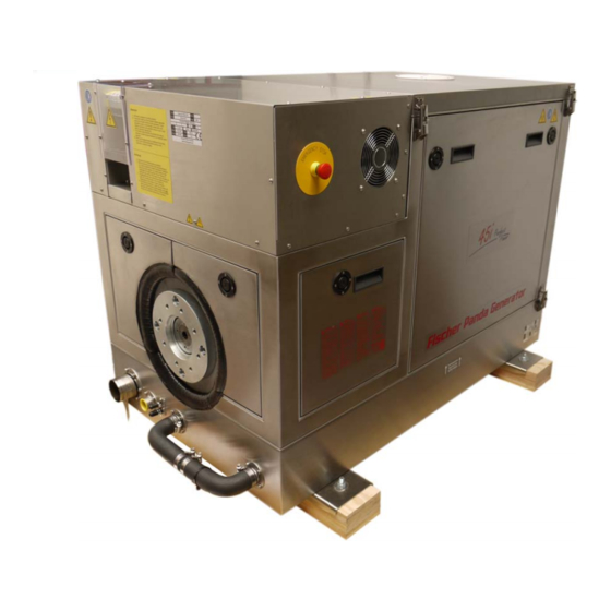
Page 41: Panda 45I Pms Generator
Panda 45i PMS generator 4. Panda 45i PMS generator 4.1 Type plate at the generator Fig. 4.1-1: Panda 15000i PMS generator Fig. 4.1-2: Type plate 8.10.14 Kapitel/Chapter 4: Panda 45i PMS generator - Seite/Page 41... -
Page 42: Description Of The Generator
Starter motor solenoid Oil pressure switch Exhaust out Raw water pump Generator housing with winding Sound cover base part PMGi 45 with integrated icontrol board Raw water hose Turbo Charger Seite/Page 42 - Kaptitel/Chapter 4: Panda 45i PMS generator 8.10.14... -
Page 43: Left Side View
PMGi 45 with integrated icontrol board Oil dipstick Emergency Stop switch Oil filter Generator housing with coil Stop solenoid Sound cover base part Fuel solenoid DC fuse Water cooled air induction elbow Actuator/Servo 8.10.14 Kapitel/Chapter 4: Panda 45i PMS generator - Seite/Page 43... -
Page 44: Front View
11) Pully for internal water pump 05) Cable for starter battery negative pol 12) DC-alternator 06) Cable for starter battery positive pol 13) Air filter 07) Raw water intake 14) Water cooled induction elbow Seite/Page 44 - Kaptitel/Chapter 4: Panda 45i PMS generator 8.10.14... -
Page 45: Back View
Panda 45i PMS generator 4.2.4 Back view Fig. 4.2.4-1: Back view PMGI Power out Generator back plate Connection point Remote control panel Connection point external ventilation valve Connection point fuel pump 8.10.14 Kapitel/Chapter 4: Panda 45i PMS generator - Seite/Page 45... -
Page 46: View From Above
4.2.5 View from above Fig. 4.2.5-1: View from above Air filter PMGi 45 Turbo charger Thermo sensor cylinder head Suction hose, air suction housing - induction elbow Oil filler neck Exhaust out Seite/Page 46 - Kaptitel/Chapter 4: Panda 45i PMS generator 8.10.14... -
Page 47: Details Of Function Units
Panda 45i PMS generator 4.3 Details of function units 4.3.1 Remote control panel - See Panda iControl manual 4.3.2 Components of the cooling system (raw- and freshwater) Fig. 4.3.2-1: Cooling system 8.10.14 Kapitel/Chapter 4: Panda 45i PMS generator - Seite/Page 47... -
Page 48: Components Of The Fuel, Air Intake And Exhaust System
Panda 45i PMS generator 4.3.3 Components of the fuel, air intake and exhaust system Fig. 4.3.3-1: Fuel, air intake and exhaust system Seite/Page 48 - Kaptitel/Chapter 4: Panda 45i PMS generator 8.10.14... -
Page 49: Components Of The Electrical System
Panda 45i PMS generator 4.3.4 Components of the electrical system Fig. 4.3.4-1: Electrical system 8.10.14 Kapitel/Chapter 4: Panda 45i PMS generator - Seite/Page 49... -
Page 50: Components Of The Lubrication System
Panda 45i PMS generator 4.3.5 Components of the lubrication system Fig. 4.3.5-1: Lubrication system Seite/Page 50 - Kaptitel/Chapter 4: Panda 45i PMS generator 8.10.14... -
Page 51: Sensors And Switches For Operating Surveillance
If the impeller pump drops out and deliveres no more raw water, the exhaust connection becomes extremely hot. Thermo-switch coil Fig. 4.3.6-3: Thermosensor coil One thermo sensor is located in the stator winding 8.10.14 Kapitel/Chapter 4: Panda 45i PMS generator - Seite/Page 51... -
Page 52: Operation Instructions - See Panda Icontrol Panel Manual
4.4 Operation instructions - See Panda iControl panel manual 4.4.1 Daily routine checks before starting - See Panda iControl manual 4.4.2 Starting generator - See Panda iControl manual 4.4.3 Stopping the generator - See Panda iControl manual Seite/Page 52 - Kaptitel/Chapter 4: Panda 45i PMS generator 8.10.14... -
Page 53: Generator Operation Instruction
Generator operation instruction 5. Generator operation instruction 5.1 Personal requirements Only instructed persons are allowed to run the generator. Instructed Persons has read the manual of the generator and all ancillary components and external equipment. He must be acquaint with the specific risks and safety instruc- tions. -
Page 54: Pre-Heating The Diesel Motor
It is harmless for the generator to deliver full nominal power for 2-3 hours. The hole conception of the Fischer Panda generator make sure, that the full power operation at extreme condition will not increase the engine temperatures over. Please note that the emissions of the generator also increase at full power operation. -
Page 55: Protection Conductor
5.3.5 Operating control system on the Fischer Panda generator Fischer Panda generators are equipped with various sensors/temperatures switches. The combustion engine is fur- ther equipped with a oil pressure control switch, which switches the motor off, if the oil pressure sinks to a particular level. -
Page 56: Starting The Generator - See Remote Control Panel Data Sheet
Generator operation instruction 5.6 Starting the generator - see remote control panel data sheet The instructions and regulations of the remote control Note: panel data sheet must be respected. Respect the safety instruction in front of this manual. 5.7 Stopping the generator - see remote control panel data sheet The instructions and regulations of the remote control Note: panel data sheet must be respected. -
Page 57: Installation Instructions
Damages caused by faulty or incorrect installation are not covered by the warranty. 6.1 Personal requirements The described installation must be done by a technical trained person or a Fischer Panda service point. 6.1.1 Hazard notes for the installation Notice: see “Safety first!”... - Page 58 Installation Instructions • Only perform installation work using commercially available tools and special tools. Incorrect or damaged tools can re- sult injuries. Warning!: Danger of fire Oil and fuel vapours can ignite at contact with ignition sources. Therefore: • No open flames during work on the generator. •...
-
Page 59: Place Of Installation
Installation Instructions Attention!: Disconnect all load. Disconnect all load during the work at the generator to avoid damages at the load. 6.2 Place of installation 6.2.1 Preliminary remark • There must be sufficient fresh air supply for the combustion air. •... -
Page 60: Advice For Optimal Sound Insulation
(i.e. in pipe) at a temperature up to a max of. 70°C (160°F). The on-board circuit must also be fitted with all essential fuses. The following figures are represantive for a Fischer Panda Hinweis generator. To locate the original connection points, please see the chapter „The Panda generator“. -
Page 61: Installation Of The Cooling System - Raw Water
The genset should have its own raw water (coolant water) inlet and should not be connected to any other engine systems. Ensure that the following installation instructions are complied with: 6.4.2 Fischer Panda installation kit - raw water Note: The following additional components will be required for the specified installation. - Page 62 Installation Instructions Through hull fitting with strainer Fig. 6.4.2-1: Thru hull fitting with strainer Sea cock Fig. 6.4.2-2: Sea cock Adapter Fig. 6.4.2-3: Adapter Raw water filter Fig. 6.4.2-4: Raw water filter Spiral coiled tube with metal spiral bead Fig. 6.4.2-5: Spiral coiled tube with metal spiral bead Seite/Page 62 - Kaptitel/Chapter 6: Installation Instructions 8.10.14...
-
Page 63: Installation Of The Through Hull Fitting In Yachts - Scheme
Installation Instructions Ventilation valve Fig. 6.4.2-6: Ventilation valve Hose clamps Fig. 6.4.2-7: Hose clamps 6.4.3 Installation of the through hull fitting in Yachts - scheme It is good practice for yachts to use a through hull fitting with Fig. 6.4.3-1: Position of the through hull fitting an integrated strainer. - Page 64 A repair is then very expensive. Replacement impeller and also a spare pump should always be on board. The old pump can be sent back to Fischer Panda for cost-effective repair. Seite/Page 64 - Kaptitel/Chapter 6: Installation Instructions 8.10.14...
-
Page 65: Raw Water Installation Scheme
Installation Instructions 6.4.6 Raw water installation scheme Fig. 6.4.6-1: Raw water installation schema 8.10.14 Kapitel/Chapter 6: Installation Instructions - Seite/Page 65... -
Page 66: Generator Installation Below Waterline
Installation Instructions 6.4.7 Generator installation below waterline If the generator cannot be attached at least 600 mm above the Fig. 6.4.7-1: Vent valve waterline, a vent valve must be installed at the raw water line. Possible heeling must be taken into consideration if installed at the "mid-ship line"! The water hose for the external vent valve is located at the back of the sound insulated capsule. -
Page 67: Indirect Cooling Of The Genset Housing (By The Heat Exchanger)
Installation Instructions Fig. 6.4.8-1: Installation scheme for direct cooling 1. Vent valve 5. Raw water filter ø 1" 2. Coolant connection block 6. Water cock ø1“ 3. Raw water pump 7. Through hull 4. Exhaust manifold 6.4.9 Indirect cooling of the genset housing (by the heat exchanger) Fig. -
Page 68: Installation Of The Cooling System - Fresh Water
Installation Instructions 6.5 Installation of the cooling system - fresh water 6.5.1 Position of the external cooling water expansion tank Position of the external cooling water expansion tank Fig. 6.5.1-1: Position of the External Cooling Water Expansion Tank The Panda generator is normally supplied with an additional, external cool- ing water expansion tank. -
Page 69: Scheme For Freshwater Circuit At Two Circuit Cooling System
Installation Instructions 6.5.2 Scheme for freshwater circuit at two circuit cooling system Fig. 6.5.2-1: Scheme for freshwater circuit at two circuit cooling system 1. Expansion tank 4. Fresh water pump 2. Exhaust manifold 5. Heat exchanger 3. Thermostat housing 6. Cooling water connection block installation 8.10.14 Kapitel/Chapter 6: Installation Instructions - Seite/Page 69... -
Page 70: Installation Of The Water Cooled Exhaust System
Installation Instructions 6.7 Installation of the water cooled exhaust system 6.7.1 Fischer Panda installation kit - Exhaust System The following additional components will be required for Note: the specified installation. You can purchase them as an installation kit or separately at Fischer Panda. -
Page 71: Installation Of The Standard Exhaust System
Installation Instructions Sleeve adapter Fig. 6.7.1-5: sleeve adapter Exhaust hose black with wireinlay Fig. 6.7.1-6: Exhaust hose black with wireinlay Seacock Fig. 6.7.1-7: Seacock Hoseclamps Fig. 6.7.1-8: Hoseclamp 6.7.2 Installation of the standard exhaust system The generator exhaust system must remain completely independent and separate from the exhaust system of any other unit(s) on board. -
Page 72: Installation Of The Waterlock
Installation Instructions Fig. 6.7.2-1: Installation Scheme Standard Exhaust System Installation of the waterlock Note!: Pay attention to the right flow direction throught the waterlock. Unfortunately, it can occasionally occur that, because of an disadvantageous mounting position of the waterlock, sea water gets into the diesel engines’... -
Page 73: Possible Cause For Water In The Exhaust Hose
Installation Instructions tainly be reasonable to immediately inject plenty penetrating oil through the intake stack and to slowly turn the engine with the starter motor. The cooling water can reach the exhaust area via the exhaust hose as well as via the cooling water feed. 6.8.1 Possible cause for water in the exhaust hose 6.8.1.1 Possible cause: exhaust hose If the cause is the exhaust hose itself, the following points are to be checked at the hose:... -
Page 74: The Volume Of The Waterlock
Installation Instructions Fig. 6.8.2-1: Installation area of the waterlock 6.8.3 The volume of the waterlock The waterlock must be measured so large, that it can take the entire amount of water flowing back from the exhaust hose. The amount of water depends on the hoses’ length (L) and its cross section. While the diesel engine is run- ning, cooling water is continuously injected into the exhaust system and is carted outside with the emissions by the exhaust gas pressure. - Page 75 Installation Instructions Fig. 6.8.3.0-1: Volume of the waterlock If there are any doubts, a verification can easily be made by temporarily using a clear-sighted hose (1) as exhaust hose. In that way, the cooling water level can be checked very easily. Fig.
-
Page 76: Ideal Position Of The Waterlock
Installation Instructions 6.8.3.1 Ideal position of the waterlock Important Note! The ideal position of the waterlock would be in center underneath the generator. Only in this position it is assured that the water level cannot change drastically in tilted position by the waterlock moving out of the center line. - Page 77 Installation Instructions Fig. 6.8.3.1-3: Tilted position 30 degrees Tilted position 30 degrees - Fig. 6.8.3.1-3 The distance of the water level, even in ideal position, changes that only 458 mm distance remain. So the critical dis- tance is under-run already. Fig.
- Page 78 Installation Instructions Summary: The preset minimum height of 600 mm must be regarded unconditionally and is only valid if the waterlock is mounted in its ideal position in center underneath the generator. A higher position is highly recommended if it has to be reckoned with tilted positions of 45 degrees.
-
Page 79: Example Of The Installation Of The Waterlock Off-Center And Possible Effects
Installation Instructions 6.8.3.2 Example of the installation of the waterlock off-center and possible effects: The following pictures are primarily relevant for an installation of the generator with the waterlock on sailing yachts. A change in the mounting position caused by tilted position does not have to be reckoned concerning motor yachts. Here it is only necessary to regard that the volume of the waterlock is measured so large that it can take the entire amount of water flowing back, and at the same time, maintains the minimum distance of 600 mm. - Page 80 Installation Instructions Fig. 6.8.3.2-3: Tilted position 30 degrees Tilted position 30 degrees - Fig. 6.8.3.2-3 The distance between the hydrostatic head and the critical point at the exhaust elbow is only 216 mm. This means that in a tilted position of 30 degrees you already face the highest risk of sea water sloshing into the combustion chamber.
- Page 81 Installation Instructions B) Installation distance between waterlock and the generator’s center line 1000 mm Fig. 6.8.3.2-5: waterlock, 1000 mm next to center line Fig. 6.8.3.2-6: Tilted position 15 degrees Tilted position 15 degrees - Fig. 6.8.3.2-6 The distance is, contrary to the original 600 mm, only 327 mm. This is very close to the critical point already. 8.10.14 Kapitel/Chapter 6: Installation Instructions - Seite/Page 81...
-
Page 82: Exhaust / Water Separator
In order to reduce the noise level of the generator unit to a minimum, an optional exhaust outlet muffler can be mounted next to the through-hull fitting. Additionally there is a component at Fischer Panda, which acts as both an „exhaust goose neck“, and water separator. - Page 83 Installation Instructions Fig. 6.9.0-1: Installation Scheme exhaust / water separator 8.10.14 Kapitel/Chapter 6: Installation Instructions - Seite/Page 83...
-
Page 84: Installation Exhaust Water Separator
- Water lock not far enough below the lowest level of the generator - Distance water lock to exhaust/water separator too large 6.10 Fuel system installation 6.10.1 Fischer Panda installation kit - Fuel system Note: The following additional components will be required for the specified installation. - Page 85 Installation Instructions Fuel hose Fig. 6.10.1-1: Fuel hose representative picture No return valve Fig. 6.10.1-2: No return valve representative picture Pre filter with water separator Fig. 6.10.1-3: Pre filter with water separator representative picture 8.10.14 Kapitel/Chapter 6: Installation Instructions - Seite/Page 85...
-
Page 86: The Following Items Need To Be Installed
Installation Instructions Pre filter with water separator Fig. 6.10.1-4: Pre filter with water separator Alternative Article representative picture Quick connector for fuel lines Fig. 6.10.1-5: Quick connector for fuel lines representative picture Hose clamps Fig. 6.10.1-6: Hose clamps representative picture 6.10.1.1 The following items need to be installed: •... - Page 87 Installation Instructions Electrical fuel pump Fig. 6.10.1-1: electrical fuel pump With the Fischer Panda generator is usually supplied an external, electrical fuel pump (DC). The fuel pump must be installed close at the fuel tank. The electrical connections is prepared at the generator.
- Page 88 Installation Instructions Fig. 6.10.1-2: Fuel system - schema 1. Fuel tank 4. Non return valve 2. external fuel pump 5. Fuel fine filter 3. external fuel prefilter with water separator 6. Generator Seite/Page 88 - Kaptitel/Chapter 6: Installation Instructions 8.10.14...
-
Page 89: Connection Of The Fuel Lines At The Tank
Installation Instructions External fine filter Fig. 6.10.1-3: externer Feinfilter At generators with Kubota EA 300 or Farymann engines, the fine filter is delivered with the generator. This fine filter should be installed in the fuel feed line next to the generator. representative picture 6.10.2 Connection of the fuel lines at the tank Note:... -
Page 90: Position Of The Pre-Filter With Water Separator
Installation Instructions 6.10.3 Position of the pre-filter with water separator Inside the generator capsule itself, there is the fuel filter installed (exception: Panda 4500). Additional fuel filters (with water separator) must be mounted outside the capsule in easily accessible places in the fuel lines between the tank intake fuel pump and the diesel motor's fuel pump. - Page 91 Installation Instructions ATTENTION! Make sure that the voltage of the starter battery fits to the start system voltage f.e. 12 V starter battery for a 12 V start system f.e. 24 V starter battery for a 24 V start system (2x12 V batteries in a row) NOTE: To avoid large voltage drops the battery should be installed as near as possible to the generator.
- Page 92 Installation Instructions Positive battery cable Fig. 6.11.1-1: Positive Battery Cable The positive (+) battery cable is connected directly to the solenoid switch of the starter. Negative battery cable Fig. 6.11.1-2: Negative Battery Cable The negative (-) battery cable is connected to the engine foot. Note! The battery negative pole may not be connected with the boat ground or with the protective grounding of the 120 V installation!
- Page 93 Installation Instructions Fig. 6.11.1-4: Connection starterbattery 12V - schema 1. Generator 3. Fuse 2. Battery block 4. Battery main switch Fig. 6.11.1-5: Connection starterbattery 24V - schema 1. Generator 3. Fuse 2. Battery block 4. Battery main switch 8.10.14 Kapitel/Chapter 6: Installation Instructions - Seite/Page 93...
-
Page 94: How To Connect Two 12V Batteries To A 24V Battery Bank
Installation Instructions 6.11.2 How to connect two 12V batteries to a 24V battery bank The starter batteries have to be connected in this order: Fig. 6.11.2-1: Installation starter battery 1. (+) cable of first battery 2. (-) cable of second battery Fig. -
Page 95: Connection Of The Remote Control Panel - See Panda Icontrol Panel Manual
Installation Instructions 4. (-) cable of first battery Fig. 6.11.2-4: Installation starter batterie Disconnect the batteries in in reverse procedure. 6.11.3 Connection of the remote control panel - See Panda iControl panel manual 6.12 Generator AC system installation ATTENTION!: Danger to Life - High voltage Before the electrical system is installed, READ the SAFETY INSTRUCTIONS of this manual FIRST! Be sure that all electrical installations (including all safety systems) comply with all... -
Page 96: Installation Pmgi Inverter - See Separate Pmgi Inverter Manual
Installation Instructions Fig. 6.12.0-1: Electrical installation - example 1. Generator 5. Starter battery DC 2. Electrical fuel pump DC 6. Fuse 3. PMGi inverter 7. Battery switch 4. iControl panel 6.12.1 Installation PMGi inverter - See separate PMGi inverter manual Seite/Page 96 - Kaptitel/Chapter 6: Installation Instructions 8.10.14... -
Page 97: Maintenance Instructions
Maintenance Instructions 7. Maintenance Instructions 7.1 Personal requirements All maintenance, if not special marked, can be done by the trained persons. Further maintenance must be done by technical personal or Fischer Panda service points. maintenance Hazard notes for the Notice!: Follow the general safety instruction at the front of this manual. - Page 98 Maintenance Instructions Danger!: Danger of poisoning Contact with engine oil, antifreeze and fuel can result in dam- age to health. Therefor: • Avoid skin contact with engine oil, fuel and antifreeze. • Remove oil and fuel splashes and antifreeze from the skin immediately.
-
Page 99: Environmental Protection
Maintenance Instructions 7.3 Environmental protection Environmental protection. Danger to the environment due to mishandling! Significant environmental damage can occur, particularly for incorrect dis- posal, if environmentally hazardous operating materials are mishandled. Therefore: • Always observe the instructions mentioned below. • Take immediate action if environmentally hazardous mate- rials reach the environment. - Page 100 Oil should be refilled, if the oil-level is under 1/3 between the minimum and the maximum mark. Fischer Panda recommends an oil-level of 2/3 between the minimum and the maximum mark. If the oil-level is under the MIN-mark, check how many operating hours went by since the last oil change, by means Seite/Page 100 - Kaptitel/Chapter 7: Maintenance Instructions 8.10.14...
-
Page 101: Refilling Oil
• if the oil-level is under the minimum mark by less than 50h, there might be a technical problem! In that case, we recommend going to a shop or a Fischer Panda service point. • if the oil is cloudy or even „creamy“, coolant might have mixed with the oil. See a garage or a Fischer Panda service point immediately. -
Page 102: Replacement Of Engine Oil And Engine Oil Filter
Maintenance Instructions 7.7 Replacement of engine oil and engine oil filter You require: - Engine oil. See attachment. - New oil filter (not with generators with EA300 engines) - Sealing for oil drain screw - Personal protective gear - Container to collect used oil (heat resistant and of sufficient size) - Open-ended wrench for oil drain screw - Paper towels and cloth... - Page 103 Maintenance Instructions 2. Loosen oil filling cap Fig. 7.7-1: Oil filling cap Unscrew the oil filling cap. This is necessary, because otherwise a vacuum will form and the oil can not com- pletely drain off. Sample picture 3. Open oil drain screw. Fig.
-
Page 104: After The Oil Change
Maintenance Instructions Oil screen with generators with EA300 engines Fig. 7.7-4: Oil screen The oil screen should be cleaned every 500 operating hours: to do so follow the instructions in the engine manual. Use spanner size 17 mm. Sample picture 6. -
Page 105: Verifying The Starter Battery And (If Necessary) The Battery Bank
Maintenance Instructions 7.8 Verifying the starter battery and (if necessary) the battery bank Check the condition of the battery. Proceed here as prescribed by the battery manufacturer. If from the battery manufacturer not otherwise mentioned. 7.8.1 Battery 7.8.1.1 Check battery and cable connections •... -
Page 106: Ventilating The Fuel System
Maintenance Instructions • Measure the electrolyte density of individual cells with a Fig. 7.8.1.3-1: Battery commercial hydrometer. The hydrometer reading (see table on following page) indicates the battery’s state of charge. During measurement, the temperature of the electrolyte should preferably be 20 °C. Electrolyte density in [kg/ l] Charge status... - Page 107 Maintenance Instructions 2. Press failure bypass switch and keep firmly pressed. Fig. 7.9-1: Failure bypass switch The electrical fuel pump must be audible. Switching on and off the solenoid valve at the generator will be audible by pressing the failure bypass switch (if capsule removed).
-
Page 108: Replacement Of The Fuel Filter
Maintenance Instructions 7.9.1 Replacement of the fuel filter Exchanging the filter, depending upon fuel contamination, should take place Fig. 7.9.1-1: Fuel Filter after 300 operational hours at the very least. The inlet must be clamped, before exchanging the filter. Remove the hoses from the used filter and fasten them to the new filter. The arrow on the filter housing indicates the direction of the fuel flow. -
Page 109: Checking The Water Separator In The Fuel Supply
Maintenance Instructions 2. Unscrew the filter element from the mount (left hand rota- Fig. 7.9.1.1-3: Fuel filter tion). 3. Screw the new filter element into the mount. Fig. 7.9.1.1-4: Fuel filter 4. Lubricate the sight glasses o-ring with a heat resistant grease (Specification: Antiseize) and screw the sight glass back into its mount (right hand rotation). -
Page 110: Replacing The Electric Starter
7.11 Replacing the Electric Starter NOTE:Representative procedure The described procedure is representative for Fischer Panda generators. The original location of the item must be taken from the generator descrip- tion of this manual. All replacements and repairs should be done by a trained person. - Page 111 Maintenance Instructions 3. Pull off rubber cap. Fig. 7.11-3: Electric starter 4. Loosen hex nut with wrench with W.A.F. 13 mm and remove the electric connections. 5. Loosen the lower attachment screw with a hex socket Fig. 7.11-4: Electric starter wrench.
- Page 112 Maintenance Instructions The upper attachment screw is visible from up top, view Fig. 7.11-6: Electric starter between engine and exhaust manifold. 6. Slide the socket wrench fitted with both extensions under the exhaust manifold and insert in the hex socket screw. Loosen upper attachment screw.
-
Page 113: Replacing The Dc Alternator
7.12 Replacing the DC Alternator NOTE:Representative procedure The described procedure is representative for Fischer Panda generators. The original location of the item must be taken from the generator descrip- tion of this manual. All replacements and repairs should be done by a trained person. - Page 114 Maintenance Instructions 3. Pull off rubber caps on the electrical terminals. Fig. 7.12-3: DC alternator 4. Remove nut and washer of the 24 V DP+ terminal (red cable) using a wrench with W.A.F. 10 mm. 5. Remove nut and washer of the exciter terminal (grey Fig.
- Page 115 Maintenance Instructions 8. Loosen bottom fixing screw of the DC alternator with a Fig. 7.12-6: DC alternator wrench with W.A.F. 12 mm (01). 9. Use a wrench with W.A.F. 12 mm (02) for the counter nut. 10.Push the DC alternator toward the thermostat housing. Fig.
- Page 116 Maintenance Instructions 14.Loosen and remove the earthing strip with a size 5 mm Fig. 7.12-9: DC alternator socket wrench. 15.Replace the DC alternator. 16.To reinstall, reverse the order of steps. Seite/Page 116 - Kaptitel/Chapter 7: Maintenance Instructions 8.10.14...
-
Page 117: Replacing The Oil Pressure Switch
7.13 Replacing the Oil Pressure Switch NOTE:Representative procedure The described procedure is representative for Fischer Panda generators. The original location of the item must be taken from the generator descrip- tion of this manual. All replacements and repairs should be done by a trained person. -
Page 118: Replacing The Oil Pressure Sensor (Optional Component)
Maintenance Instructions 7.13.1 Replacing the oil pressure sensor (optional component) 1. Unscrew both connectors (01) on the oil pressure sensor. Fig. 7.13.1-1: Oil pressure sensor 2. Loosen and remove oil pressure sensor 6R3 using a Fig. 7.13-2: Oil pressure sensor wrench with W.A.F. -
Page 119: Replacing A Thermoswitch
7.14 Replacing a Thermoswitch NOTE:Representative procedure The described procedure is representative for Fischer Panda generators. The original location of the item must be taken from the generator descrip- tion of this manual. All replacements and repairs should be done by a trained person. - Page 120 Maintenance Instructions 3. Disconnect electric supply line of the thermoswitch. Fig. 7.14-3: Thermoswitch 4. Loosen thermoswitch with a wrench with W.A.F. 22 mm. Fig. 7.14-4: Thermoswitch 5. Before installing the new thermoswitch, check the label for Fig. 7.14-5: Thermoswitch correct item. 6.
-
Page 121: Replacing The V-Belt At Kubota 02/05 Series
7.15 Replacing the V-belt at Kubota 02/05 series NOTE:Reprehensive procedure The described procedure is representative for Fischer Panda generators. The original location of the item must be taken from the generator descrip- tion of this manual. All replacements and repairs should be done by a trained person. - Page 122 Maintenance Instructions 3. Push alternator towards the thermostat housing. Fig. 7.15-3: Replacing the V-belt 4. Replace the V-belt (Quad Power XPZ 862). 5. The V-belt is tensioned by pulling back the alternator. The Fig. 7.15-4: Replacing the V-belt V-belt should yield approx. 1 cm when pushed in with a thumb.
-
Page 123: Replacing The Injection Nozzles
7.16 Replacing the Injection Nozzles NOTE:Representative procedure The described procedure is representative for Fischer Panda generators. The original location of the item must be taken from the generator descrip- tion of this manual. All replacements and repairs should be done by a trained person. - Page 124 Maintenance Instructions 3. Loosen the union nut on the injection lines (1). Wrench Fig. 7.16-3: Injection nozzles with W.A.F. of 17 mm. For assembly: • Blast dust out of the lines using compressed air. Then, re- assemble the lines by proceeding in the reverse order of steps.
- Page 125 Maintenance Instructions Removing the nozzle heat shield ring seal within the scope of Fig. 7.16-5: Injection nozzles the maintenance work. IMPORTANT! • Use a phillips screwdriver (1) with a diameter greater than the hole in the heat ring seal (approx. 6 mm (1/4 in)). 1.
-
Page 126: Replacing The Glow Plugs
7.17 Replacing the Glow Plugs NOTE:Representative procedure The described procedure is representative for Fischer Panda generators. The original location of the item must be taken from the generator descrip- tion of this manual. All replacements and repairs should be done by a trained person. - Page 127 Maintenance Instructions 3. Remove the glow plug connector. Fig. 7.17-3: Glow plugs 4. Loosen the glow plug using a socket wrench with a long Fig. 7.17-4: Glow plugs size 10 mm socket. 5. Remove glow plug. Fig. 7.17-5: Glow plugs 6.
-
Page 128: Replacing The Valve Cover Gasket At Kubota 02 Series
7.18 Replacing the valve cover gasket at Kubota 02 series NOTE:Representative procedure The described procedure is representative for Fischer Panda generators. The original location of the item must be taken from the generator descrip- tion of this manual. All replacements and repairs should be done by a trained person. -
Page 129: Replacing The Water Pump At Kubota 02 Series
7.19 Replacing the Water Pump at Kubota 02 series NOTE:Representative procedure The described procedure is representative for Fischer Panda generators. The original location of the item must be taken from the generator descrip- tion of this manual. All replacements and repairs should be done by a trained person. -
Page 130: Adjusting The Valve Clearance At Kubota 02 Series
7.20 Adjusting the valve clearance at Kubota 02 series NOTE:Representative procedure The described procedure is representative for Fischer Panda generators. The original location of the item must be taken from the generator descrip- tion of this manual. All replacements and repairs should be done by a trained person. -
Page 131: Replace The Air Filter Mat
Maintenance Instructions 1. Cam shaft Fig. 7.20-1: Valve open 2. Cam follower 3. Push rod 4. Adjusting screw 5. Counter nut 6. Rocker arm 7. Valve 8. Crankshaft 1. Cam shaft Fig. 7.20-2: Valve closed 2. Cam follower 3. Push rod 4. -
Page 132: Alternative Replacement Of The Air Filter Mat With Pull Out Holder
Maintenance Instructions 1. Open the air suction housing by loosen the six screws on Fig. 7.20-1: Air suction housing the housing cover. Use spanner size 8 mm. 2. Change the air filter mat. Fig. 7.20-2: Opened air suction housing 3. Close the suction air housing. 7.20.2 Alternative replacement of the air filter mat with pull out holder 1. - Page 133 Maintenance Instructions 2. Tip the two fasteners 90°. Fig. 7.20.2-2: Air suction housing with pull out holder 3. Pull the filter mat holder out. Fig. 7.20.2-3: Air suction housing with pull out holder 4. Replace the air filter mat. Fig. 7.20.2-4: Air suction housing with pull out holder 5.
-
Page 134: Alternative Replacement Of The Air Filter At Housing With Snap Fasteners
Maintenance Instructions 7.20.3 Alternative replacement of the air filter at housing with snap fasteners 1. Open the combustion air housing by loosening the closure Fig. 7.20.3-1: Air suction housing on the right side of the housing. 01. Closure 2. Open the combustion air housing by loosening the closure Fig. - Page 135 Maintenance Instructions ATTENTION!: Risk of scalding. The expansion tank is supplied with a pressure relief valve in the cap with 500 mbar. It is possible when operating the gener- ator hot cooling water can leak here if there is an overpressure. When working always wear protective clothing and ensure an adequate installation location.
-
Page 136: Anti-Freeze In The Cooling Water Circuit
Maintenance Instructions Switch off the generator after approx. 10 seconds of operation! 5. Repeat the steps 1-4 till no more air comes out of the venting screw at the thermostat housing. Close the venting screws. Fill up the expansion tank up to max. marking. Close the expansion tank. - Page 137 Maintenance Instructions Fig. 7.20.6-1: Fresh water circuit at a two circuit cooling system - Schema 1. Expansion tank 4. Freshwater pump 2. Exhaust manifold 5. Heat exchanger 3. Thermostat housing 6. Cooling water connection block Some generators are equipped with an additional cooling water Fig.
-
Page 138: Replacing The V-Belt At Kubota 02/05 Series
7.21 Replacing the V-belt at Kubota 02/05 series NOTE:Reprehensive procedure The described procedure is representative for Fischer Panda generators. The original location of the item must be taken from the generator descrip- tion of this manual. All replacements and repairs should be done by a trained person. -
Page 139: The Raw Water Circuit
Maintenance Instructions 2. Loosen the fixing screw below the alternator. Fig. 7.21-2: Alternator fixing screw Wrench with width across flats of 12 mm. 01. Fixing screw 3. Push alternator towards the thermostat housing. Fig. 7.21-3: Replacing the V-belt 4. Replace the V-belt (Quad Power XPZ 862). 5. -
Page 140: Causes With Frequent Impeller Waste
Maintenance Instructions The raw water filter should be released regularly from arrears. In each case Fig. 7.22.1-1: Raw water filter the water cock must be closed before. It is mostly sufficient to beat the filter punnet. If water should seep through the cover of the raw water filter, this may be sealed in no case with adhesive or sealant. -
Page 141: Replacement Of The Impeller
Maintenance Instructions 7.23.1 Replacement of the impeller Close the raw water stop cock. Fig. 7.23.1-1: Raw water cock Representative picture Raw water pump on the front side of the genset. Fig. 7.23.1-2: Raw water pump Representative picture Remove the cover of the raw water pump by loosen the screws Fig. - Page 142 Maintenance Instructions Fig. 7.23.1-4: Impeller pump Pull to the impeller with a multigrip pliers of the wave. Mark the impeller, to make sure that these is used in the correct position at re-installation. Representative picture Check to the impeller for damage and replace it if necessary. Fig.
-
Page 143: Generator Failure
Generator Failure 8. Generator Failure 8.1 Personal requirements The work described here, unless otherwise indicated, are performed by the operator. More repair work may be performed only by specially trained personnel or by authorized repair shops (Fischer Panda service points). This is especially for working on the valve timing, fuel injection system and the engine repair. 8.2 Safety instructions for this chapter Notice!: Also consider the general safety instructions at the first pages of this manual. -
Page 144: Tools And Measuring Instruments
Generator Failure Danger!: Danger of poisoning Contact with engine oil, antifreeze and fuel can result in dam- age to health. Therefor: - Avoid skin contact with engine oil, fuel and antifreeze. - Remove oil and fuel splashes and antifreeze from the skin immediately. - Do not inhale oil and fuel vapours. -
Page 145: Overloading The Generator
Generator Failure 8.4 Overloading the generator Please ensure that the genset is not overloaded. Overloading occurs when the electrical load (demand) induces a load torque in the generator which is higher than that which the diesel drive motor can provide. Overloading causes the engine to run rough, burn oil, creates excessive exhaust (environmentally unfriendly) and even to stall. -
Page 146: Low Generator-Output Voltage
Generator Failure 8.4.1 Low generator-output voltage ATTENTION! Before working on the System read the section “Safety first!” on Page 14. If the produced alternating voltage is too low, switch the load off, in order to relieve the generator. Mostly the problem already solved. -
Page 147: Dirty Fuel Filter
Generator Failure 8.5.2 Dirty fuel filter If the fuel filter is dirty change the filter element. For replacing the filter element see section C.3.1, “Replacing fuel filter,” on page 79 Fuel filter 1. Fuel filter element Fig. 8.5.2-1: Fuel filter 8.6 Troubleshooting table For troubleshooting see section 9.1, “Troubleshooting,”... - Page 148 Generator Failure Seite/Page 148 - Kaptitel/Chapter 8: Generator Failure 8.10.14...
-
Page 149: Tables
Tables 9. Tables 9.1 Troubleshooting GENERATOR OUTPUT VOLTAGE TOO LOW If the generator delivers less than 24V current („undervoltage“), there can be various reasons for this: Cause Solution PGMi is overloaded. Reduce the electrical load. (Switch off load) Motor is not reaching the rated rpm. Refer to „motor faults“... - Page 150 Tables DROP IN THE SPEED OF THE MOTOR Cause Solution Too much oil. Drain oil. Lack of fuel. Check fuel supply system: - fuel filter, renew if necessary - check fuel pump - check fuel lines (bleed if necessary) Lack of intake air. Check air intake paths.
-
Page 151: Technical Data
Tables 9.2 Technical data 9.3 Technical Data Fig. 9.3-1: Technical Data Panda 4000s Panda 4200 FCB 4500FCB Type Farymann Farymann Farymann 18W430 18W430 18W430 Governor mechanic mechanic mechanic Automatic start booster Cylinder Bore 82 mm 82 mm 82 mm Stroke 55 mm 55 mm 55 mm... - Page 152 Tables Panda 6500 Panda 8000 NE Panda 9000 ND Panda 10000 NE Panda 12000 NE Panda 7 mini Panda 8 mini Panda 9 mini Idle running speed ² 3120 rpm 2900 rpm 3120 rpm 3100 rpm 2900 rpm Valve clearance (engine cold) 0,2 mm 0,2 mm 0,2 mm...
- Page 153 Tables ² progressive speed by VCS ³ 0,35l/kW electrical power, the randomized values between 30% and 80% of the rated speed Fig. 9.3-4: Technical data Panda 30 IC PMS Panda 40 LN Panda 47 LN Panda 60 MB Panda 75 MB PVM-NE PVM-NE Type...
- Page 154 Tables Panda 7,5-4 Panda 9-4 Panda 12-4 Panda 17-4 Panda 22-4 Cylinder head nut torque 63,7 - 68,6 Nm 63,7 - 68,6 Nm 68Nm 68Nm 93,1 - 98 Nm Compression ratio 23:1 23:1 22:1 22:1 Lubrication oil capacity 5,1 l 5,1 l 6,0l 9,5 l...
- Page 155 Tables ³ 0,35l/kW electrical power, the randomized values between 30% and 80% of the rated speed Fig. 9.3-7: Technical Data igenerators Panda 5000i Panda 8000i Panda 10000i Panda 15000i Panda 25i Type EA300 Z482 Z602 D902 Kubota V1505 Governor iControl2 iControl2 iControl2 iControl2...
-
Page 156: Diameter Of Conduits
Tables Panda 45i Fuel consumption ³ approx. 1,95 - 5,2l Oil consumption max. 1% of fuel consumption Oil specification API CF Cooling water requirement for seawater cir- 55‐80 l/min cuit (Marine generators only) Permissible max. permanent tilt of engine a) 25° crosswise to the longitudinal axis b) 20°... -
Page 157: Cable Cross Section
Tables Generator type Ø Cooling water conduit Ø Exhaust conduit Ø Fuel conduit [mm] Freshwater Seawater Supply Return [mm] [mm] [mm] [mm] Panda PMS-HD 22-4 KU Panda PMS-HD 30-4 KU Panda PMS-HD 40-4 KU Panda PMS-HD 60-4 DZ Panda PMS-HD 70-4 DZ Panda PMS-HD 85-4 DZ Panda PMS-HD 110-4 DZ Panda PMS-HD 130-4 DZ... -
Page 158: Coolant Specifications
Use a mixture of water and antifreeze. The antifreeze needs to be suitable for aluminium. The antifreeze concentra- tion must be regularly checked in the interests of safety. Fischer Panda recommend to use the product: GLYSANTIN PROTECT PLUS/G 48 Engine coolant automotive industry Product description Product name GLYSANTIN ®... -
Page 159: Coolant Mixture Ratio
Tables 9.7.1 Coolant mixture ratio Water/antifreeze Temperature 70:30 -20°C 65:35 -25°C 60:40 -30°C 55:45 -35°C 50:50 -40°C 9.8 Fuel Use a clean No. 2 Diesel fuel oil (SAE J313 JUN87) according to ASTM D975 and EN 590. Do not use alternative fuel, because its quality is unknown or it may be inferior in quality. Kerosene, which is very low in cetane rating, adversely effects the engine. - Page 160 Tables Seite/Page 160 - Kaptitel/Chapter 9: Tables 8.10.14...
-
Page 161: Inverter Panda Pmgi 45
Inverter Panda PMGi 45 Fischer Panda Datenblatt / Datasheet 10. Inverter Panda PMGi 45 Art Nr. xx.xx.xx.xxx - 400 V / 50 Hz xx.xx.xx.xxx -400 V / 60 Hz Bez. Panda PMGi 45 Document Hardware Software Actual: Replace: PGMi 45_eng.fm... -
Page 162: Safety Instruction
Inverter Panda PMGi 45 Fischer Panda Datenblatt / Datasheet 10.1 Safety instruction The generator may not be taken into use with the cover removed. The rotating parts (belt-pulley, belts, etc) must be covered and protected so that there is no danger to life and body! If a sound insulation cover must be produced at the place of installation, then well-placed signs must show that the generator can only be switched on with a closed capsule. -
Page 163: Socket Pins Of The Pmgi 45
Inverter Panda PMGi 45 Fischer Panda Datenblatt / Datasheet 10.2.1 Socket pins of the PMGi 45 Socket 1 AC - PMGi out Fig. 10.2-1: Socket 1 1. Ground (cable green/yellow) 2. Live L1 3. Live L2 4. Live L3 5. Neutral (cable blue) 6. - Page 164 Inverter Panda PMGi 45 Fischer Panda Datenblatt / Datasheet Attention! Make sure that the connection between the generator and the PMGi is secured. Never connect or disconnect the PMGi while the generator is running. This will destroy the PMGi (it may burn or explode).
-
Page 165: Settings For The Use Of Igenerators With Power Inverter
Inverter Panda PMGi 45 Fischer Panda Datenblatt / Datasheet 10.4 Settings for the use of iGenerators with power inverter ATTENTION: Wrong settings can destroy the For the use of power inverter with the PMGi, the settings of the power inverter must be modified. -
Page 166: Settings In The Victron Ve Configure Ii Software - Inverter
Inverter Panda PMGi 45 Fischer Panda Datenblatt / Datasheet 10.4.2 Settings in the Victron VE Configure II Software - Inverter Fig. 10.4.2-1: Settings in the Victron VE configure II Software 10.4.2.1 Assist current boost factor To reduce the action of the power inverter on the iGenerator, the Assist current boost factor must be reduced from 2.0 to1.3. -
Page 167: Operation Manual
Inverter Panda PMGi 45 Fischer Panda Datenblatt / Datasheet 10.5 Operation manual 10.5.1 Primary remarks / Winter operation The PMGi can operate in the range of -20°C to +40°C. 10.5.2 Load at the PMGi Do not overload the PMGi. It will go on error. -
Page 168: Installation Of The Pmgi
Inverter Panda PMGi 45 Fischer Panda Datenblatt / Datasheet 10.7 Installation of the PMGi Note! See the safety instruction in your Generator and iControl Man- ual. The rules of the respective regional authority must be adhered to. Only an electrician may carry out installation of the electrical connections for safety reasons. -
Page 169: Technical Data
Inverter Panda PMGi 45 Fischer Panda Datenblatt / Datasheet For the use of the PMGi with an isolation controlled grid, the internal PWE-N Bridge must be disconnected. 10.8 Technical Data 10.8.1 General Data PMGi is part of the Panda i-series generator. Its not allowed to be used with other generators or applications. -
Page 170: Pmgi Out
Inverter Panda PMGi 45 Fischer Panda Datenblatt / Datasheet 10.8.3 PMGi out Fig. 10.8.3-1: Technische Daten PMGit / Technical Data PMGi / PMGi Out PMGi 4000 230 V PMGi 5000 230 V PMGi 5000 120 V Nominale Ausgangsspan- 230 V VAC +/- 5 % ohne... - Page 171 Inverter Panda PMGi 45 Fig. 10.8.3-2: Technische Daten PMGi / Technical Data PMGi / PMGi Out PMGi 8000 230 V PMGi 8000 120V PMGi 10000 230 V Nominale Ausgangsspan- 230 V VAC +/- 5 % ohne 120 V VAC +/- 5 % ohne 230 V VAC +/- 5 % ohne nung Last / without Load / sans...
- Page 172 Inverter Panda PMGi 45 Fig. 10.8.3-3: Technische Daten PMGi / Technical Data PMGi / PMGi Out PMGi 10000 120 V Nominale Ausgangsspan- 120 V VAC +/- 5 % ohne nung Last / without Load / sans charge Nominal Voltage Regelung Regulation Stabilität (Kurzzeit (30sec)) Stability (short term (30sec))
- Page 173 Inverter Panda PMGi 45 Fig. 10.8.3-4: Technische Daten PMGi / Technical Data PMGi / PMGi Out PMGi 15000 400 V PMGi 15000 230 V PMGi 15000 120 V Nominale Ausgangsspan- 400 V VAC +/- 5 % ohne 230 V VAC +/- 5 % ohne 120 V VAC +/- 5 % ohne nung Last / without Load / sans...
- Page 174 Inverter Panda PMGi 45 Fig. 10.8.3-5: Technische Daten PMGi / Technical Data PMGi / PMGi Out PMGi 25 230 V PMGi 25 400 V PMGi 45 400 V Nominale Ausgangsspan- 230 V VAC +/- 5 % ohne 400 V VAC +/- 5 % ohne 400 V VAC +/- 5 % ohne nung Last / without Load / sans...
-
Page 175: Pmgi Protections
Inverter Panda PMGi 45 10.9 PMGi protections 10.9.1 Short circuit To operate the short circuit protection a fuse must be put in series with the live wire. The minimum requested feature for this fuse are the following. 2.75 10.0 >1h <30min 5ms to 150ms 2ms to 15ms... - Page 176 Inverter Panda PMGi 45 Seite/Page 176 - Kaptitel/Chapter 10: Inverter Panda PMGi 45 8.10.14...
-
Page 177: Panda Icontrol2
Panda iControl2 Operating Manual Open-loop and closed-loop control system for Fischer Panda generators Fischer Panda GmbH Panda iControl2_eng.R07 8.10.14... -
Page 178: Current Revision Status
Reproduction and modification of the manual is permitted only after agreement with the manufacturer! Fischer Panda GmbH, 33104 Paderborn, reserves all rights regarding text and graphics in this document. Details are given to the best of our knowledge. No liability is accepted for correctness. Please note: technical modifications aimed at improving the product may be implemented without prior notice. -
Page 179: Safety Instructions For The Panda Icontrol2
NOTE: Fischer Panda genset manual. If these instructions are not on hand, they can be requested from Fischer Panda GmbH, 33104 Paderborn, Germany. An external signal may trigger an automatic start-up. WARNING: Automatic start-up The generator must not be operated with the cover WARNING: removed. - Page 180 Safety instructions for the Panda iControl2 Disconnect battery before working on the generator WARNING: The battery must always be disconnected (first the negative terminal, then the positive terminal) if work on the generator or electrical system is to be carried out, so that the generator cannot be unintentionally started.
-
Page 181: General Operation
General operation 2. General operation 2.1 The Panda iControl2 panel The "Panda iControl2 panel" control panel is the control and display unit for the Panda iControl2 control system and represents the interface between the user and the Panda iControl2 controller. The integrated display serves to present the most important data of the system as well as warnings and error messages. -
Page 182: Starting Preparation / Checks (Daily)
General operation 2.2 Starting preparation / Checks (daily) 2.2.1 Marine version 1. Oil level control (ideal level: 2/3 MAX). The level should be about 2/3 of the maximum level of a cold engine. Further, if installed, the oil level of the oil-cooled bearing must be controlled before each start - see sediment bowl at generator front cover!. -
Page 183: Operation
General operation 2.3 Operation 2.3.1 Switching the controller on and off The Panda iControl2 controller is switched on and off with the On/Off button on the Panda iControl2 panel. Press and hold the On/Off button until the start screen with the panda bear appears on the display. The controller is switched off by actuating the On/Off button once more. -
Page 184: Operating Modes
General operation • Oil pressure status • Cylinder head temperature • Temperature of exhaust manifold • Winding temperature • Speed/RPM • Utilisation in percent Fig. 2.3.2-1: Default display screen The Display shows the iControl board input voltage. Note: At generator systems with 12 V starter system these is equal with the starter battery voltage. -
Page 185: Start-Up Mode
General operation Fig. 2.3.3.1-1: Service information screen The total operating hours of the generator are given on the default display screen and on the service information screen. By actuating the cursor-up and cursor-down button in stand-by mode, the service screen can be accessed. This screen is marked with a screwdriver/spanner symbol. -
Page 186: Override Mode
General operation The controller will only perform one starting attempt. If Note: the generator could not be started, the text output "STARTING FAILS" informs you of the failure of the generator starting attempt. Acknowledging the message with the cursor-up, cursor-down, or the Start/Stop button on the Panda iControl2 panel will return the system to stand-by mode. - Page 187 General operation Display screen for single phase generators With the single phase i-series generators, there is an Fig. 2.3.3.4-2: Inverter screen in operation mode additional screen in operation mode for the inverter data. This screen provides the current inverter output voltage and the inverter temperature.
- Page 188 General operation This screen provides the latest inverter output voltage of the Fig. 2.3.3.4-7: Phase voltage L3 single phases with the matching conductor current and the circuit board temperature. The inverter will be switched off at a circuit board temperature of 75 °C. You can access the inverter screen by actuating the cursor-up button while in operation mode.
-
Page 189: Stop Mode
After the delay time, the generator will be stopped automatically. You can interrupt the delay time by pressing the start/stop button. (Not recommend by Fischer Panda. The Engine may overheat) Fig. 2.3.3.5-1: Delay time... - Page 190 General operation The autostart function will remain active even after the Warning!: Automatic start-up controller is switched off and on again with the On/Off button. To deactivate the autostart function, the flag in the EEPROM must be reset with "Disable". Siehe “Activating/deactivating the autostart function ("Autostart")”...
-
Page 191: Other Operating Functions
Dimtime (dimming time) Time until the display switches to dimmed mode, 0-225s, 0= function deactivated Config Password protected area for Fischer Panda associates and Fischer Panda service points Network ID Settings for the network ID of the panel Save & Exit... -
Page 192: Setting The Brightness Of The Backlight ("Backlight" And "Dimtime")
General operation 2.4.2 Setting the brightness of the backlight ("backlight" and "dimtime") The brightness of the display backlight of the Panda iControl2 panel can be varied in ten increments (0-9). Also, the display can be dimmed with a timer if no button is actuated on the control panel for a parameter is able period. To adjust the default brightness and the dimmed brightness, the set-up menu offers the items "backlight 1"... -
Page 193: The Configuration Menu ("Config")
Settings in this area must only be entered by Fischer STOP! Panda associates and Fischer Panda service points. The "config" sub-menu is a password protected area in which the generator type can be selected, and generator parameters in the EEPROM can be modified. - Page 194 General operation To activate the autostart function, select the item Fig. 2.4.6-1: Set-up menu "Autostart" in the set-up menu using the cursor buttons and confirm the selection with the Start/Stop button. In the "Autostart" sub-menu, you can select between the Fig.
-
Page 195: Resetting The Service Interval ("Service")
General operation Then, the controller is shut down. Fig. 2.4.6-6: Goodbye screen prior to shutting down After switching the controller back on, the display status Fig. 2.4.6-7: Default display screen in autostart mode field reading "AUTOSTART" indicates that the autostart function is active, or, if it reads "STANDBY", this means that the autostart function was deactivated: The autostart function will remain active even after the... -
Page 196: Priming The Fuel System ("Prime Fuel")
General operation Resetting the time until the next service Fig. 2.4.7-1: Resetting the time until the next service By actuating the Start/Stop button again, you can reset the service interval to the original interval. The service interval for each generator type is stored in the software. The controller is switched off after resetting the service interval. -
Page 197: Installation
WARNING: Properly dimension your system. designed and adequate for „standard“ installation situations. As Fischer Panda does not know the specific installation and operating situation (e.g. special vehicle shapes, high travel speeds, and special application conditions, etc. ), this installation specification can only serve as a guideline and example. -
Page 198: Disposal Of The Components
Installation DANGER TO LIFE! - Improper operation can result in WARNING: Electric voltage health impairment and death. Electric voltages of more than 48 V are potentially lethal in any situation. The rules of the respective regional authority must be adhered to during installation. For safety reasons, only an electrician may carry out the installation of the electrical connections of the generator. -
Page 199: Panda Icontrol2 Panel With Installation Housing
Autostart USTART/STOPP Autostart A jumper between terminal 6 and 7 closes the autostart contact. A jumper between terminal 6 and 7 closes the autostart contact. Use only original Fischer Panda connecting cables. Note: 8.10.14 Kapitel/Chapter 3: Installation - Seite/Page 199... -
Page 200: Dimensions
Installation 3.3 Dimensions Fig. 3.3-1: Housing of the Panda iControl2 panel Seite/Page 200 - Kaptitel/Chapter 3: Installation 8.10.14... -
Page 201: Wiring Of The Panda Icontrol2 Controller
The Panda iControl2 controller is connected to the wire harness with the 18-pin jack. The centre 6-pin jack is designed for the Fischer Panda standard bus. The Panda iControl2 panel is connected to this jack. The Fischer Panda CAN bus is connected to the 6-pin jack at the bottom right of the circuit board. The configuration of the connectors is given in the subsequent tables. -
Page 202: Terminal Assignments On The Panda Icontrol2 Controller
Terminal Terminal description Function UBUS Bus supply voltage Fischer Panda bus ground, ground connection between Panda iControl2 controller and Panda iControl2 panel REIZ Exciter line, is switched to ground by the panel if the controller is to switch on DATA+... -
Page 203: Start-Up
The original start-up log of the generator must be sent to Note: Fischer Panda to obtain the full warranty. Make sure that you retain a copy for your records. The corresponding forms are included in the generator manual. - Page 204 Installation Leere Seite / Intentionally blank Seite/Page 204 Kapitel/Chapter 3: Installation 8.10.14...
-
Page 205: Maintenance
Maintenance 4. Maintenance 4.1 Maintenance of the iControl2 controller The iControl2 controller is maintenance-free. The fuses of the controller are self-healing. 4.1.1 Cleaning the iControl2 controller The housing shall be cleaned within the scope of the overall generator cleaning. The housing can be wiped off with a soft, lightly dampened cloth. - Page 206 Maintenance Leere Seite / Intentionally blank Seite/Page 206 Kapitel/Chapter 4: Maintenance 8.10.14...
-
Page 207: Warnings And Error Messages
Warnings and error messages 5. Warnings and error messages To enable the safe operation of the generator, the Panda iControl2 controller is programmed with a series of warnings and error messages that influence the generator operation. 5.1 Warnings Warnings are issued when the variable being monitored, e.g. temperature, reaches a defined warning threshold. The warnings are issued on the Panda iControl2 panel display via the cyclical display of the word „HIGH“... -
Page 208: Warning Messages
Warnings and error messages 5.1.2 Warning messages All warning messages defined for the Panda iControl 2 and the corresponding display output are compiled in the subsequent table. Fig. 5.1.2-1: Warning messages Warning message on the display Meaning of warning message „HIGH“... -
Page 209: Error Messages
Cylinder head temperature too high FAULT: WINDING Winding temperature too high FAULT: EXHAUST Exhaust manifold temperature too high NO CONNECTION BUS ERROR Communication error on Fischer Panda bus STARTING FAILS Generator start has failed PROBLEM WITH FUEL SUPPLY! Fuel supply not suitable FAULT: OILPRESS... -
Page 210: Bus Errors
15.0 V 5.2.3 Bus errors If the communication connection is lost on the Fischer Panda bus, an error is output on the display after a period of 10 seconds: This error will occur if at least one of the two data lines Fig. -
Page 211: Annex
Annex 6. Annex 6.1 Technical data 6.1.1 Technical data for iControl2 control unit Fig. 6.1.1-1: Technical data for iControl 2 control unit iControl 2 control unit Supply voltage 12V-13.5V (12V automotive) Current consumption, nominal 175 mA Current consumption, stand-by 2.5 mA Operating temperature -20°C to +85°C Storage temperature... - Page 212 Annex Leere Seite / Intentionally blank Seite/Page 212 Kapitel/Chapter 6: Annex 8.10.14...
Need help?
Do you have a question about the 45i pms and is the answer not in the manual?
Questions and answers