
Related Manuals for Famsun Muyang SJPS215

Summary of Contents for Famsun Muyang SJPS215
- Page 1 Muyang SJPS215 Single-screw Extruder Operation Manual Prior to use, please read through this operation manual carefully and keep it properly for reference in the future...
- Page 2 Foreword 1. Thanks for purchasing Muyang SJPS215 Single-Screw Extruder. 2. This Operation Manual is an important technical document for safe and correct operation of SJPS215 Single-Screw Extruder. 3.Prior to operation, please read this operation manual carefully and get to know the safety instructions, performances, requirements for installation and operation etc.
-
Page 3: Table Of Contents
CONTENTS 1 Safety instructions ..............................1 1.1 Environment conditions ............................1 1.2 Description of warning signs ..........................1 1.3 Description of safety signs ............................. 2 1.4 Special notes ................................5 1.5 Safety instrustions in transportation, storage and installation ................6 1.6 Safety instructions in operation, inspection and maintenance ................ - Page 4 5.2 Operation procedure of startup (auto-control mode) ................... 55 5.3 Shutdown operation ............................. 59 5.4 Emergency stop and restart procedure ......................... 60 6 Maintenance and repair............................61 6.1 Precautions for inspection, repair and maintenance .................... 61 6.2 Daily inspection and periodical inspection ......................62 6.2.1 List of daily inspection items ..........................
- Page 5 6.11 .1 Spare parts..............................104 6.11.2 Spare part list ..............................104 6.11.3 Order list of spare parts ..........................123 7 Appendix ................................124 7.1 List of documents with shipment ........................124 7.2 Contact information ............................124 7.3 Muyang SJPS215 Single-Screw Extruder (list of operation manuals) ...............125...
-
Page 6: Safety Instructions
1 Safety instructions 1.1 Environment conditions Please install the equipment according to the following conditions for safe operations. (1)Please install the equipment indoors according to following conditions: .Ambient temperature range (-10~+40℃) .Relative humidity range: 30~85% . Altitude: less than1000m . Make indoor clean and vented. .... -
Page 7: Description Of Safety Signs
1.3 Description of safety signs (1)Relevant safety signs are posted at the corresponding dangerous positions of the equipment to personal safety. (2)All the safety signs are indicated in Fig.1-1~Fig.1-12. On basis of good understanding of these safety signs, install, adjust, operate, maintain and inspect the equipment according to the contents indicated by these signs. - Page 8 Fig.1-3 Check lubrication level Fig.1-4 Prevent scald (high temperature) Fig.1-5 Do not remove the guard shield Fig.1-6 Do not climb or stand on the equipment. Fig.1-7Wear protective gloves Fig.1-8 Maintenance to follow the operation manual. Fig.1-9 Double-shaft direction Fig.1-10 Right-hand direction sign Fig.1-11 Left-hand direction sign Fig.1-12 Clockwise direction The SJPS215 Extruder set can be divided into 4 elements: a feed bin, a feeder, a conditioner and a...
- Page 9 Fig.1-13 Posted position of safety signs on the principal machine 5, 6, 11 6, 7, 8 2, 4 Fig.1-14 Posted position of safety signs on the conditioner...
-
Page 10: Special Notes
Fig.1-15 Posted positions of safety signs on the feeder Fig.1-16 Posted positions of safety signs on the feed bin 1.4 Special notes (1)The said equipment operators refer to all personnel who should participate in operation, inspection and maintenance etc. (2)The equipment operator must possess satisfactory understanding of the Operation manual. (3)The owner has the duty and obligation to educate all operation personnel with the safety instructions of the Operation Manual for the equipment. -
Page 11: Safety Instrustions In Transportation, Storage And Installation
should be in charge of the training and observe the national, local and company’s other safety regulations. (6)All the responsibilities for any accidents or damages to the equipment shall not be borne by manufacturer and commission agent if the equipment is not operated according to the Operation manual. -
Page 12: Safety Instructions In Operation, Inspection And Maintenance
(10)The cover plate, protection hood or guard are usually installed and delivered together with the machine. They can only be disassembled with tools. And the machines required with the protection devices can never be put into work until such devices have been properly installed. 1.6 Safety instructions in operation, inspection and maintenance (1)The operation, inspection, repair and maintenance of the equipment shall be carried out only by the trained technical personnel according to applicable specifications provided... -
Page 13: Personal Protection
(15)Ensure the safety of the electric system. Before the electric circuit is powdered off, it is strictly prohibited to open the terminal box to avoid electric shock. (16)The electric control system of the extruder must comply with following instructions. Otherwise, the supplier will deny the technical safety responsibility. ①The electric control system of the extruder must be supplied by Jiangsu Muyang Holdings Co., Ltd. -
Page 14: Explosion Protection: Precautions Against Dust Explosion And Fire Hazard
⑤As for handling heated or cooled parts and components of the machine, watch for the danger of burning or scalding, frost-bitting. ⑥If you have pressed the emergency-stop switch to shut down the machine and you want to reset the switch, it is not permissible to only re-press this button rather to turn on the main switch to restart the machine. - Page 15 ② Check and clean the magnetic separator regularly, at least once a day. ③ In order to avoid heat generation, it is necessary to regularly check the functions of all main shafts and bearings, at least once a week, and to fill up with lubricant on regular basis. (3)Electric apparatus Regularly check the electric apparatus and articles, and special attention should be paid to the following points:...
-
Page 16: Other Precautions (Environmental Protection Measurements)
1.9 Other precautions (environmental protection measurements) If you decide not to use the machine any longer after it is used for a certain number of years (about 8-10 years), the measures for environmental protection and reutilization should be taken. (1) Drain the liquids inside the machine (like motor oil, gearbox oil, brake oil and coolant etc.) into special containers and send them to the designated workshop. -
Page 17: General
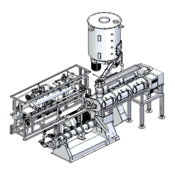
2 General 2.1 Application and adaptability SJPS215 Single-Screw Extruder developed by MuyangHoldings Co., Ltd (hereafter referred to as "extruder") is mainly used for processing floating and sinking feed in aquafeed industry As for a pioneer application in new fields, please consult Muyang experts for further technology support. 2.2 Main components and working principle 2.2.1 Main components The mechanical equipment of extruder system is mainly composed of feeding bin, feeder, conditioner,... -
Page 18: Working Process
2.2.2 Working process First of all, the materials prepared, blended and pulverized enter the feeding bin with bridge-breaking device for further process. Then the materials in bridge-breaking feeding bin are delivered by the feeder to the double-shaft differential-speed conditioner (DDC) for conditioning where mixed with injected steady, continuous and metered steam, water, and other liquids. -
Page 19: Feeder
The bin body is cylindrical and equipped with an agitator at the bottom to ensure continuous and steady feeding to the next process. The bin has a certain capacity to provide operator enough time for troubleshooting in case of flow stop from the previous procedure. The rotation direction of bridge-breaking feeding bin can be forward or reverse, and the rotation direction of bridge-breaking tower should be in line with the discharge direction of the feeder. -
Page 20: Conditioner
Fig.2-4 Relationship between frequency and feeding rate for the production of common freshwater fish feed 2.3.3 Conditioner Conditioner for this system adopts SPTZ_39 or SPTZ_45 triple-shaft conditioner, which consists of support bracket, a DDC conditioner, a single-pass conditioner, and steam and water addition system. See Fig. - Page 21 The conditioner is made of complete stainless steel and divided into two layers: the upper layer is the single-shaft with high-speed blending while the lower layer is heat-retentioner for a certain time upon sufficient blending to obtain conditioning of a longer time period and a higher gelatinization degree. In the whole conditioning process, water and most or all steam is added to the single-cylinder conditioner at the upper layer.
- Page 22 Upper single-shaft conditioner Lower conditioner Fig.2-6 Schematic diagram of triple-shaft Fig.2-7 Exterior view of triple-shaft conditioner conditioner The technical parameters of the triple-shaft conditioner are shown in Table2-3 Table2-3The technical parameters of the triple-shaft conditioner Device name Model Motor power Conditioning time 2~3min SPTZ39-2...
-
Page 23: Principal Machine Of Extruder
2.3.4 Principal machine of extruder The principal machine is the core of whole extruder system, and generally consists of main motor, guard, machine stand, bearing pedestal, off-product bypass, support bracket, extrusion barrels, discharge device, cutting device and pipeline rack. See Fig.2-8. 1.Motor base 2.Main motor 3.Principal machine stand 4.Pipeline rack... - Page 24 2.3.5.1 Full-automatic control pipeline system 1.Water inlet pipe φ34×3.5 2.Water to extrusion barrel φ22×3 3.Steam to extrusion chamber DN40 4.Steam to jacket DN20 5.Pipeline of safety valve DN40 6.Main steam inlet valveDN100 7. Steam 8.Water to conditioner φ27×3.5 to the conditioner DN80 Fig.2-9 Full automatic pipeline system The pipeline support of the full-automatic control system is shown in Fig.2--9 (full-automated pipeline system).
- Page 25 Flow direction Water, Flow control Flow checking Steam, Material, and Other additives Feedeback Computer Setting flow Fig.2-10 Liquid (feed mash) addition principle Generally, the extruder equipped with full automatic pipeline system is controlled by a touch screen, which requires a control box on job-site. See Fig.2-11. The control box with touch screen mainly includes: touch screen, display instrument of barrel temperature, display instrument of conditioner temperature, door lock, power switch, cutter speed control knob, emergency stop button, weight display of material and alarm.
- Page 26 2.3.5.2 Semi-automatic control pipeline system and its control The Semi-automatic pipeline system is shown in Fig.2-12 1.Water inlet φ34×3.5 2.Steam to extrusion barrel DN40 3.Steam to jacket DN20 4.Pipeline for safety valve DN40 5.Main valve for steam DN100 6.Steam to conditioner DN80 7.Water outlet φ34×3.5 Fig.2-12Semi-automatic pipeline system...
- Page 27 Fig.2-14 Glass tube flowmeter Fig.2-15 Push-button control box of manual control system The semi-automatic control system uses button-type panel control without touch screen. See Fig.2-15. The sole control performance of the control box of semi-automatic pipeline system is the control of steam pipelines to conditioner and extrusion barrel.
-
Page 28: Functions And Features
value of the temperature at the conditioner outlet. While the steam addition rate to the extrusion barrel is mainly managed by the expansion effect of the pellets. Therefore, operation of extruder with manual pipeline system calls for rich experience. The extruder by manual control shall require the operator with high professional qualifications. -
Page 29: Specifications Of The Extruder
3 Specifications of the extruder 3.1 Basic Specification 3.1.1 Model description Model of the extruder is composed of specialty code, variety code, primary form and main specifications (as follows). Upgrated or improved code Main construct: nominal diameter of screw, mm Primary form: wet extrusion Variety code: extruder Specialty code: dedicated for feed industry... -
Page 30: Working Condition
3.2 Working condition (1) Requirements for material grinding For aquafeed with an extruder, the mixing homogeneity and ground particle size of feed mash should be guaranteed. For aquafeed produced by different die holes, the requirements to the granularity of feed mash are different. -
Page 31: Transportation And Installation
4 Transportation and installation 4.1 Transportation (1) Hoisting ①It is required to disassemble the belt and guard of belt pulley before hoisting so as to protect the principal machine from damage by hoisting cable. See Fig.4-1 Hoisting diagram. Fig.4-1 Hoisting diagram of extruder ②... - Page 32 Fig.4-3 Hoisting diagram of upper conditioner Fig4-4 Hoisting diagram for lower conditioner ③ When hoisting, the cables shall be capable of taking the weight of the hoisted equipment (see Table4-1 for the weight of equipment) and not be too short in order to avoid any damage to the equipment.
-
Page 33: Equipment Installation
② If a packing case is not used, take water-proof protection and prevent the goods from collision and overturn of the equipment during transport. ③ If a packing case is used, fix the complete machine and accessories securely in the case and leave certain clearances away from the boards of the packing case, so as to avoid collision and damage in transport. - Page 34 The exhaust device is configured with two exhaust cylinders which can be delivered with extruder and installed on site as accessories. In the figure, the height5805 includes the heights of the two exhaust cylinders, and the height of 5805 can be adjusted by the two exhaust cylinders, and the height after adjustinig is 4801 and 3797 respectively.
- Page 35 The exhaust device is configured with two exhaust cylinders which can be delivered with extruder and installed on site as accessories. In the figure, the height5884 includes the heights of the two exhaust cylinders, and the height of 5884 can be adjusted by the two exhaust cylinders, and the height after adjustinig is 4880 and 3876 respectively.
-
Page 36: Installation Of Bridge-Breaking Feeding Bin And Feeder
4.2.2 Installation of bridge-breaking feeding bin and feeder One basic reference data of the extruder control system is the material flow rate. The additions of water, steam, and other liquids in the system shall be based on the material flow rate. Therefore, the stability of material flow will directly affect that of the whole extruder operation. -
Page 37: Installation Of The Pipeline System
4.2.4 Installation of the pipeline system Determine the installation location for pipeline system, preferably not too far away from the principal machine. A distance too far will cause waste of connection material of pipelines and also control delay. Allowed by the field conditions, the optimum location of pipeline system is over by and parallel to the rear side of the principal machine &... - Page 38 1.Water tank 2.Ball valve DN25 3.Filter DN25 4.Water pump 5.Water inlet pipe φ34×3.5 6.Water return pipe φ34×3.5 7.Water return valve DN25 8.Water inlet to extruder barrel DN15 9.Water inlet to conditioner φ27×3.5 (DN20) Fig.4-7 Watter addition to extruder barrel and conditioner (auto-control) Note: The equipment in the dotted box is offered by Muyang.
- Page 39 4.2.4.3Steam pipeline of pipeline system 1.Main steam intake valve DN100 2.Steam to the conditioner DN80 3.Steam to the extruder barrel DN40 4.Steam to jacket of extruder barrel DN20 5.Safety valve pipeline DN40 Fig.4-9 Joints of steam pipelines on pipeline system Relevant Requirements for each joint of steam pipes on pipeline system: ...
-
Page 40: Installation Of Belt Pulley And V-Belt
temperature into the conditioner and the extruder barrel, and thus at the same time to utilize the energy more effectively. Jacket condensate outlet: Steam turns into condensate that drains through the outlet. The condensate mingled with a certain amount of steam is in small amount and at higher temperature that can drain here via a pipe. -
Page 41: Electric Installation
To install belt pulley and V-belts, follow the procedures below: ① Check each V-belt for any pollutions by grease or dirt; ② Keep V-belt in a proper tension: When V-belt is too loose, it tends to slippage. On the other hand, if it is too tight, it leans to a great tensile force to the shaft, which will decrease its service life. - Page 42 AC 3P / N / PE 380V & 50Hz FU21~23 Danfoss L1; L2; L3 VVVF1 V.F.D VLT-2800 U; V; W V2 W2 V1' W1' VVVF1 U1; V1; W1 V.F.D ABB-ACS355 U2; V2; W2 M1 3~ 3~ 3~ ② ③ ① Fig.
- Page 43 KADL KM3Y KM3S 3~ 3~ 3~ ④ ⑤ ⑥ Fig. 4-13(b) Schematic diagram of electric control for SJPS 215 Single-Screw Extruder (2) Note: KADL is the electronic over-current relay, PA2 is installed at the high-voltage electric cabinet; PA3 is installed in the control box on site. ④Main motor for principal machine of extruder;...
- Page 44 Danfoss L1; L2; L3 VVVF6 V.F.D VLT-2800 U; V; W V6' W6' VVVF6 U1; V1; W1 V.F.D ABB-ACS355 U2; V2; W2 M6 3~ 3~ 3~ ⑧ ⑦ ⑨ Fig. 4-13(c) Schematic diagram of electric control for SJPS 215 Single-Screw Extruder (3) Note:⑦Cutter motor;...
- Page 45 SAJS SB1+ E-STOP1 VVVF1 VVVF1 V.F.D V.F.D ABB-ACS355 VLT-2800 E-STOP2 300Ω 300Ω KAJS ④ ⑤ KAJS ① ② ③ Fig. 4-13(d) Schematic diagram of electric control for SJPS 215 Single-Screw Extruder (4) Note: ①Emergency stop ②Unlock (start the oil pump->main motor->conditioner->feeder under interlocking conditions);③Start/Stop feeder motor ④Feeding control(wiring of Danfoss frequency converter) ⑤Feeding control(wiring of ABB frequency converter)
- Page 46 KM3Y KM3S SB3+ SB7+ KM3S KAJS KM3Y KM3Y KM3S KM3Y ① ③ ④ ⑤ ② ⑥ Fig. 4-13(e) Schematic diagram of electric control for SJPS215 Single-Screw Extruder (5) Note: ①Start/Stop oil pump motor ②Start/Stop main motor ③Y-△ switching delay; ④Suction and close for main contactor of extruder ⑤△ running of main ⑥Y-running of main motor motor of extruder...
- Page 47 SB5+ SB4+ 1A≤IR≤10A SB2+ 014 012 (TZ61) KADL KAJS SQ-TZ1~8 KAJS KADL TZ69 ② ⑤ ① ④ ③ Fig. 4-13(f) Schematic diagram of electric control for SJPS215 Single-Screw Extruder (6) Note: ①Start/Stop for bridge-breaking motor; ②Door protection; ③Start/Stop for upper-pass conditioner; ④ Start/stop for lower-pass conditioner ⑤ Over-current relay...
- Page 48 VVVF6 SB6+ VVVF6 V.F.D V.F.D ABB-ACS355 VLT-2800 300Ω 300Ω ② ③ ① Fig. 4-13(g) Schematic diagram of electric control for SJPS 215 Single-Screw Extruder (7) Note: ①Start/Stop of cutting motor; ②Cutting motor control (wiring of Danfoss frequency converter); ③Cutting motor control (wiring of ABB frequency converter)
- Page 49 ST-TZ1 ST-TZ2 TZ21 TZ11 TZ22 TZ12 ℃ ℃ XTN-7000-Ⅱ ① ② Fig. 4-13(h) Schematic diagram of electric control for SJPS 215 Single-Screw Extruder (8) Note: ①On/off of bypass solenoid valve ②Conditioning temperature indicator...
- Page 50 Q010 Q011 Q012 ℃ AC220V (COM) (RX)(TX) 18 19 XMDA 7D082 Fig. 4-13(i) Schematic diagram of electric control for SJPS215 Single-Screw Extruder (9) Note: This part is for temperature display of extruder barrel.
- Page 51 Temperature measurer Protection switch ST_TZ1 ST_TZ2 SQ_TZ6 SQ_TZ7 SQ_TZ8 SQ_TZ1 SQ_TZ2 SQ_TZ3 SQ_TZ4 SQ_TZ5 0.75mm 6 0.75mm 2 0.75mm To control room/ Fig.4-14(a) Schematic diagram of electric wiring for SPTZ39_2/SPTZ45_2 Conditioner...
- Page 52 SJPS______型膨化机腔体电气接线图 2012-04-09 The Schematic Electrical Connection Sheet of the SJPS______ Extruder's Antrum 腔体温度检测ST2~7 旁通 Temperature measurement Bypass ST 2 ST 3 ST 4 ST 5 ST 6 ST 7 AC 230V 3 × 0.75mm 12 × 0.75mm 到控制室/To control room Fig.4-14(b) Schematic diagram of electric wiring of SJPS 215 extruder Special note: The following diagrams for the connection of pipeline system are selective according to actual requirement.
- Page 53 2012-04-09 SJPS________ 型膨化机管路架电气接线图1(全自动) The Schematic Electrical Connection Sheet 1 of the SJPS_________ Extruder's Pipe frame 膨化腔水调节阀 膨化腔蒸汽调节阀 DDC水调节阀 DDC蒸汽调节阀 膨化腔蒸汽流量计 DDC蒸汽流量计 膨化腔水流量计 DDC水流量计 膨化腔蒸汽截止阀 DDC蒸汽截止阀 Extruder steam proportional DDC steam proportional Steam flow Sensor Water flow sensor DDC Steam valve Extruder water proportional Extruder steam flow Sensor DDC water proportional Extruder water flow Sensor...
- Page 54 2012-04-09 SJPS________ 型膨化机管路架电气接线图2(全自动) The Schematic Electrical Connection Sheet 2 of the SJPS_________ Extruder's Pipe frame 膨化腔蒸汽调节阀 膨化腔水调节阀 DDC水调节阀 DDC蒸汽调节阀 膨化腔蒸汽流量计 DDC蒸汽流量计 膨化腔水流量计 DDC水流量计 膨化腔蒸汽截止阀 DDC蒸汽截止阀 Extruder steam proportional DDC steam proportional Steam flow Sensor Water flow sensor DDC Steam valve Extruder steam flow Sensor Extruder water proportional DDC water proportional Extruder water flow Sensor...
- Page 55 The Schematic Electrical Connection Sheet 3 of the SJPS_________ Extruder's Pipe frame 膨化腔水调节阀 膨化腔蒸汽调节阀 DDC水调节阀 DDC蒸汽调节阀 膨化腔蒸汽流量计 DDC蒸汽流量计 膨化腔水流量计 DDC水流量计 膨化腔蒸汽截止阀 DDC蒸汽截止阀 Extruder steam proportional DDC steam proportional Steam flow Sensor Water flow sensor DDC Steam valve Extruder water proportional Extruder steam flow Sensor DDC water proportional Extruder water flow Sensor...
- Page 56 2012-04-09 SJPS________ 型膨化机管路架电气接线图4(全自动) The Schematic Electrical Connection Sheet 4 of the SJPS_________ Extruder's Pipe frame 膨化腔水调节阀 膨化腔蒸汽调节阀 DDC水调节阀 DDC蒸汽调节阀 膨化腔蒸汽流量计 DDC蒸汽流量计 膨化腔水流量计 DDC水流量计 膨化腔蒸汽截止阀 DDC蒸汽截止阀 DDC water proportional DDC steam proportional Steam flow Sensor Extruder water proportional Water flow sensor DDC Steam valve Extruder steam proportional Extruder steam flow Sensor Extruder water flow Sensor...
- Page 57 2012-04-09 SJPS________ 型膨化机管路架电气接线图5(全自动) The Schematic Electrical Connection Sheet 5 of the SJPS_________ Extruder's Pipe frame 膨化腔蒸汽调节阀 膨化腔水调节阀 DDC水调节阀 DDC蒸汽调节阀 膨化腔蒸汽流量计 DDC蒸汽流量计 膨化腔水流量计 DDC水流量计 膨化腔蒸汽截止阀 DDC蒸汽截止阀 Extruder steam proportional DDC steam proportional Steam flow Sensor Water flow sensor DDC Steam valve Extruder water proportional Extruder steam flow Sensor DDC water proportional Extruder water flow Sensor...
- Page 58 SJPS______型膨化机管路架电气接线图6(半自动) 2012-04-09 The Schematic Electrical Connection Sheet 6 of the SJPS________ Extruder's Pipe frame 膨化腔蒸汽流量计 DDC蒸汽流量计 膨化腔蒸汽截止阀 膨化腔蒸汽调节阀 DDC 蒸汽调节阀 DDC蒸汽截止阀 Extruder steam proportional DDC steam proportional Extruder steam flow Sensor Steam flow Sensor Extruder Steam valve DDC Steam valve SL 1 SL 2 YV21...
- Page 59 SJPS______型膨化机管路架电气接线图7(半自动) 2012-04-09 The Schematic Electrical Connection Sheet 7 of the SJPS________ Extruder's Pipe frame 膨化腔蒸汽流量计 DDC蒸汽流量计 膨化腔蒸汽截止阀 膨化腔蒸汽调节阀 DDC 蒸汽调节阀 DDC蒸汽截止阀 Extruder steam proportional DDC steam proportional Extruder steam flow Sensor Steam flow Sensor Extruder Steam valve DDC Steam valve SL 1 SL 2 YV21...
-
Page 60: Operations
5 Operations 5.1 Special notes The operator must get to know the description of "operations" before operating the equipment, and also should carefully read the Operation Manual of touch screen. This part describes the general operation of start and stop of the extruder only. For more detailed operations, please refer to "Operation manual of touch screen". - Page 61 Fig.5-2 on touch screen. Switch water and steam to "automatic" mode on the image of "liquid application" (of extruder barrels) in Fig.5-3 on touch screen. 【Note】: ①The default mode of touch screen after startup is "manual". After it is switched to automatic, the touch screen is off.
- Page 62 Steam SP% value of conditioner (percentage of throughput); Steam SP% value of extruder barrel (percentage of throughput); (as needed according to actual demand) Steam SP% value of extruder barrel (percentage of throughput); (as needed according to actual demand) Fig.5-4 Parameter setting Fig.5-5 Important parameters...
- Page 63 weight reaches to the set upper limit, pneumatic gate will automatically closes (if material weight in the bin has already reached to the upper limit, this step will be skipped; see Fig.5-4 for material upper limit); Feeder operates automatically; ...
-
Page 64: Shutdown Operation
Conditioner Water: SP%=20% SP=1000kg/h Steam of conditioner: SP%=10% SP=500kg/h Water of extruder barrel: SP%=5% SP=250kg/h Steam of extruder barrel: SP%=15% SP=750kg/h In operation, if the conditioning moisture of the materials is found too small and it is required to increase the water addition, just go straight to increase the conditioner water SP% value, i.e. -
Page 65: Emergency Stop And Restart Procedure
water & steam should be stopped by the operator according to corresponding requirements. When system executes the automatic shutdown, switch "AUTO" to "MANU" in the “production process” image, to stop the rest of the equipment by hand. 【Note】: Generally the shutdown should follow the sequence from top equipment to the bottom; ... -
Page 66: Maintenance And Repair
6 Maintenance and repair 6.1 Precautions for inspection, repair and maintenance Besides safety instructions in Chapter 1, comply with the following instructions for inspection, repair and maintenance. Cut off power first before inspection, commissioning, repair and maintenance. Only can manual operation to open access doors and guards be allowed when power is off and extruder is at complete stop. -
Page 67: Daily Inspection And Periodical Inspection
6.2 Daily inspection and periodical inspection During daily and periodical inspection, stop the machine immediately and take proper steps in case of any abnormality in machine operation. Resume the operation after confirming that the machine is recovered to normal conditions. 6.2.1 List of daily inspection items Table 6-1 List of daily inspection items Position... -
Page 68: List Of Periodical Inspection Items
Table 6-2 Check list of rated power and current of motor Rated current (A) Rated power(kW) Remarks 2-pole 4-pole 0.75 6.2.2 List of periodical inspection items Table 6-3 List of periodical inspection items Position Inspection item Cycle Solution Check whether belt is in good Belt Every 6 months Adjusting... -
Page 69: Maintenance Of Mechanical Parts
Speed gear motor: ZL-2lithium lubricating grease or ISOV 9220 Chain: GB492-65Zn-3; 6.3 Maintenance of mechanical parts (1)Keep the discharge mechanism running smoothly and brush the joints with proper amount of lubricant oil. (2) Replace the lubricant grease regularly for each bearing with grease type of sodium base grease (GB492-65) Zn-3. -
Page 70: Oil Drain And Refill
6.4.2 Oil drain and refill 1.Vent hood 2.Oil refill inlet 3.Cover plate of bearing pedestal 4.Oil drainage outlet 5.Bearing box Fig.6-1 Bearing pedestal (1) For oil change, drain the oil at the following two positions: Position I: see Fig.6--1(bearing pedestal), remove the screw at the position of “oil drainage outlet” to ... -
Page 71: Adjustment Items And Methods
greased weekly. Lack of lubricant here may cause the wearing of sealing ring in the feeding barrel and water & material leakage during operation. Table 6-2 Digram of lubricating points 6.6 Adjustment items and methods 6.6.1 Adjustment of configuration In aquafeed production, the configuration of screw could be changed according to the formula and the requirements of finished products. -
Page 72: Removal And Installation Of Taper Sleeve
6.6.2 Removal and installation of taper sleeve 1.Sprocket; 2.Removal bolt holes; 3.Taper sleeves; 4.Fastening bolts; 5.Shaft; 6.Key Fig.6-3 Schematic diagram of taper sleeve installation and disassembly The belt pulley of extruder main shaft uses taper sleeve as its installation style. The disassembly and installation methods are as following (see Fig.6-3 for the installation and Disassembly of the taper sleeve): (1)For disassemble of the taper sleeve and sprocket, ①... - Page 73 Fig.6-4 Explosive view of bearing pedestal assembly...
- Page 74 Table 6-5 List of bearing pedestal assembly Muyang code Part name Remarks O- ring 258×7 Q10301083 Oil seal 170×200×15 Q10304011 Rear end cover MYPH00210099 Screw M10×40 AAO1004001 Flared pipe joint d6(M10×1) S02190001 Screw M10×16 AAL1001601 Wearing sleeve(II) MYPH00210100 O- ring 145×5.3 Q10301011 Nut M150×2 FAG15002...
-
Page 75: Malfunction And Troubleshooting
(5) Installation order of sealing element of bearing pedestal at feeding end: As shown in Fig.6-4, install two pieces of Part #30 (O-ring180×3.55) and one piece of Part #31(wearing sleeve I) on the main shaft and grease Part #30; ... - Page 76 degree Rotation speed of main motor too Reduce the rotating speed. high. Change the open area of die plate or Open area of the die plate does adjust the output. not match the output. Product length too long or Adjust cutting transmission Cutter speed too low or too high...
-
Page 77: Tools For Repair And Maintenance
6.8 Tools for repair and maintenance Table6-7 Tools for repair and maintenance Tool name Spec. Function Hexagon socket head cap screw on chain wheel of taper sleeve, according to the parameter list of Torque wrench chain wheel of taper sleeve for the moment of force group inner... -
Page 78: Long-Term Out-Of-Service
6.9 Long-term out-of-service If the machine is to be halted for a long time, thoroughly clean both inside and outside to avoid rusting of the machine and aging of rubber parts. 6.10 Exploded diagram of various parts There are mainly two objectives to give the exploded diagram of various parts: ... -
Page 79: Feeder
6.10.2 Feeder Fig.6-6 Structure diagram of feeder Table 6-9 List of parts and components of feeder Muyang Part name Remarks TWLL00611305 Door plate series Door TWLL00611331 Centerline distance between inlet and outlet is 900 Door TWLL00611332 Centerline distance between inlet and outlet is 1000 Door TWLL00611333 Centerline distance between inlet and outlet is 1100... - Page 80 Door TWLL00611354 Centerline distance between inlet and outlet 3200 TWLL00611304 Door sealing series Door seal TWLL00611355 Centerline distance between inlet and outlet 900 Door seal TWLL00611356 Centerline distance between inlet and outlet 1000 Door seal TWLL00611357 Centerline distance between inlet and outlet 1100 Door seal TWLL00611358 Centerline distance between inlet and outlet 1200...
- Page 81 Screw rotor series Ⅱ TWLL00691377 Screw rotor TWLL00691304A Centerline distance between inlet and outlet is 900 Screw rotor TWLL00691305A Centerline distance between inlet and outlet is 1000 Screw rotor TWLL00691306A Centerline distance between inlet and outlet is 1100 Screw rotor TWLL00691307A Centerline distance between inlet and outlet is 1200 Screw rotor...
-
Page 82: Upper-Pass Conditioner
6.10.3 Upper-pass conditioner Fig.6-7a Structure diagram of upper conditioner Fig.6-7b Structure diagram for upper-pass conditioner(Upper-pass rotor SPTZ019000352) Fig.6-7c Structure diagram for upper-pass conditioner(door assembly SPTZ019000381) - Page 83 Table 6-10 List of parts and components for upper-pass conditioner Muyang code Part name Remarks Motor Y2-160M-4-11(wiring from left M01093002 side) Belt pulley of motor Q1802015001 Belt pulley bushing_BUSH2517 hole Q16251703 V-belt_SPB2120_standard PAE2120 Belt pulley Q1802050001 Belt pulley bushing_BUSH3535 hole Q16353502 65_standard NSK Bearing with pedestal UCF212...
-
Page 84: Lower-Pass Conditioner
6.10.4 Lower-pass conditioner Fig.6-8a Structure diagram of lower-pass conditioner (SPTZ39_2) Fig.6-8b Structure diagram of lower-pass conditioner (SPTZ39_2) - Page 85 Table6-11a List of parts and components for low-pass conditioner (SPTZ39_2) Muyang code Part name Remarks Steam escape device SCTZ00291328 Rubber gasket SCTZ00210002 XCE-118(two pieces on Limit switch H02010024 upper-pass) Coupling GL11FJ1-75×142 ZAB00200101 Reducer box M390S-22 R04020017 Belt pulleySPB180 Q1802018001 Taper sleeve 2517 Hole 48 X070100025 V-belt SPB2032 PAE2032...
- Page 86 Fig.6-8d Structure daigram of lower-pass conditioner (SPTZ45_2) Table6-11b List of parts and components for conditioner (SPTZ45_2) Code Designation Remarks Steam escape device SCTZ00291328 Rubber gasket SCTZ00210002 XCE-118(two pieces on Limit switch H02010024 upper-pass) Coupling ZAB00300101 GL11FY-85×172 Reducer box R04020018 MY450 Belt pulleySPB224-06 Q1802022401 BUSH3535(φ50)
- Page 87 Fig.6-8e Structure diagram of big access door assembly, small access door assembly, big rotor and small rotor of lower-pass conditioner (SPTZ39_2) (Small rotor SPTZ019000531, big rotor SPTZ019000541, small access door assembly SCTZ00291314, big access door assembly SCTZ00291317) Table 6-12a List of parts and components for big access door assembly, small access door assembly, big rotor and small rotor of lower-pass conditioner Muyang code Part name...
- Page 88 Fig.6-8f Structure diagram of big access door assembly, small access door assembly, big rotor and small rotor of lower-pass conditioner (SPTZ45_2) (Small rotor SPTZ00291416, big rotor SPTZ00291417.small access door assembly SCTZ00690017, big access door assembly SCTZ00690020) Table 6-12b List of parts and components for big access door assembly, small access door assembly, big rotor and small rotor of lower-pass conditioner Code Designation...
-
Page 89: Steam And Water Addition Pipeline For Upper Conditioner (Sptz45_2, Sptz39_2)
6.10.5 Steam and water addition pipeline for upper conditioner (SPTZ45_2, SPTZ39_2) Fig.6-9a Structure diagram for steam and water addition pipeline of upper-conditioner(upper-pass steam pipeline SPTZ019000631) Fig.6-9b Structure diagram for steam and water addition pipeline of upper-conditioner(water addition pipe SPTZ019000651) Table 6-13 List of parts and components of steam and water addition pipeline for upper-pass conditioner Muyang code Part name... -
Page 90: Seal Plate Assembly And Bearing Pedestal Assembly Of Conditioner
Carbon steel external thread D20 S02050201 Shut-off valve DN20 S01020102004 DN20×200 Flexible metallic hose Length is determined on site S02150008 Elbow joint for steam supply SPTZ011001431 Chock plug DN25 S02080401 Reducing tee DN25×20 S02031002 Carbon steel external thread D25 S02050301 Flexible metallic hose DN25×600 Length is determined on site S02150023... - Page 91 Fig.6-10b Structure diagram for bearing pedestal assembly of lower-condition(SPTZ39_2) Fig.6-10c Structure diagram for bearing pedestal assembly of lower-conditioner(SPTZ45_2) Table 6-14 Spare parts list for seal plate and bearing pedestal Code Designation Remarks AAO1003001 Bolt M10×30 GB/T70.1 GAE01001 Washer 10 GB/T93 GAB01001 Washer 10 GB/T97.1...
-
Page 92: Steam Pipeline For Lower-Pass Conditioner
SCTZ00610029 Seal ring SPTZ00291418 Welded bearing pedestal assembly 6.10.7 Steam pipeline for lower-pass conditioner Fig.6-11a Structure diagram of steam pipeline (SPTZ39_2) Table 6-15a Spare parts and components list of steam pipeline Muyang code Part name Remarks Flexible metallic hose DN80×400 S02150007 YJR5/2C-400 Shut-off valve DN80... - Page 93 Fig.6-11b Structure diagram of steam pipeline (SPTZ45_2) Table 6-15b Spare parts and components list of steam pipeline Muyang code Part name Remarks Flexible metallic hose DN80×400 S02150007 YJR5/2C-400 Shut-off valve DN80 S01020808001 BSA1 Steam inlet pipeline SPTZ00291401 Stainless steel inner-joint DN20 S02050202 GB/T3287 Shut-off valve DN20...
-
Page 94: Main Motor And Power Transmission
6.10.8 Main motor and power transmission Fig.6-12 schematic diagram of main motor and power transmission Table 6-16 List of parts and components of main motor and power transmission(250kW) Muyang code Part name Remarks MotorY2-355M-4/B3(250kW) M01222001 250KW Taper sleeve5050-95 X070100052 250KW Motor belt-pulley SJPS011003621 250KW... -
Page 95: Extruder Barrel
6.10.9 Extruder barrel Fig.6-13 Structure diagram of extruder barrels Table6-18 List of parts of extruder barrels Muyang code Part name Remarks Lip-shape oil seal 180×210×15 Q10302058 Feeding barrel section SJPS019000711 Steam inlet assembly SJPS019000691 Welded assembly of conical feeding barrel liner SJPS019000651 Welded assembly of steam inlet barrel SJPS019000681... -
Page 96: Screw Head Assembly
6.10.10 Screw head assembly Fig.6-14 Structure diagram of screw head assembly Table6-19 List of parts and components of screw head assembly Muyang code Part name Remarks Check ring SJPS011002821 Feeding screw head SJPS011002761 Conical feeding screw head SJPS011002771 Pressure lock A SJPS011002801 Screw head in middle section A SJPS011002781... -
Page 97: Discharge Device
6.10.11 Discharge device Fig.6-15 Structure diagram of discharge device Table6-20 Spare part list of discharging device Muyang code Part name Remarks Bolt M14×130 AAO1413003 Type Ⅰdie plate assembly315 MYPH01990041 315KW Type Ⅰdie plate assembly SJPS019000881 250KW Type Ⅱdie plate assembly MYPH01990038 Bolt M14×80 AAO1408003... -
Page 98: Typeⅰdie Plate Assembly
6.10.12 TypeⅠdie plate assembly Fig.6-16 Structure diagram of TypeⅠdie plate assembly Table 6-21 List of parts and components of typeⅠdie plate assembly Muyang code Part name Remarks AAO1405001 Bolt M14×50 Type Ⅰ floating feed die plate Ф3.0 MYPH00281001 315KW Type Ⅰfloating feed die plate Ф3.0 SJPS011003001 250KW SJPS011002961... -
Page 99: Cutting Rotor Assembly
Table 6-22 List of parts and components of TypeⅡ die plate assembly Muyang code Part name Remarks AAO1404001 Bolt M14×40 TypeⅡfloating feed die plate Ф2.0 MYPH00210180 TypeⅡdie plate holder MYPH00210182 AAO0803501 Bolt M8×35 AAO1403003 Bolt M14×30 Type Ⅱfeed flow distribution cone MYPH00210199 SJPS011004072 Hole plate... -
Page 100: Lubrication Oil Way
Bolt M5×10 AAO0501001 Thin blade assembly (Type Ⅱ die plate) MYPH01990016 Cutter holder MYPH00410013 Pressure plate MYPH00410014 Fit Type Ⅱ die plate Cutter blade 0.3 MYPH00210183 Cutter blade 0.5 MYPH00210184 Cutter blade 0.8 MYPH00210185 Bolt M5×10 AAO0501001 6.10.15 Lubrication oil way Fig.6-19 Structure diagram of lubrication oil way Table 6-24 List of parts and components of lubrication oil way Muyang code... -
Page 101: Cutting Blade Installation Fixture
6.10.16 Cutting blade installation fixture Fig.6-20 Structure diagram for cutting blade installation fixture Table6-25 Spare parts list of cutting blade installation fixture Muyang code Part name Remarks AAO0802001 Bolt M8×20 MYPH00210187A Washer MYPH00210186 Cutting blade installation fixture 6.10.17 Steam pipeline system Fig.6-21 Structure diagram of steam pipeline system Table6-26 List of parts and components of steam pipeline Muyang code... -
Page 102: Water Pipeline System
Safety valve D40 S01010404011 Strainer_FIG33-100mesh_DN65_SPIRAX S01021400016 Pressure reducing valve DN50 S01021005001 Vortex shedding flowmeter DN80 H04040017 Pneumatic ball valve DN80 JX00004494 Pneumatic regulator_DN65-KE73-Flange_PN16 S01020706501 _SPIRAX Actuator S02240001 Locater S02250001 6.10.18 Water pipeline system Fig.6-22 Structure diagram of water pipeline system Table6-27 List of parts and components of water pipeline Code Part name... -
Page 103: Cutting Device
6.10.19 Cutting device Fig.6-23 Schematic diagram for structure of cutting device Table 6-28 List of parts of cutting device Muyang code Part name Remarks Q02990140 Double spokes hand wheel Q02990156 Knob with double handles HAA0302001 Cylindrical pin 3×20 Q02010021 Latch type pressing handle (extruder) 6.10.20 Pipeline by principal machine... - Page 104 Fig.6-24 Schematic diagram for structure of pipeline by principal machine...
- Page 105 Table6-29 List of parts of pipeline by principal machine Muyang code Part name Remarks T-joint stainless steel 3-way ball valve S01010201514 D15 (flange) Stainless steel elbow DN15 S02020102 Shut-off valve Dg40 S01010104011 Flexible metallic hose DN15×700 S02150004 Flexible metallic hose DN15×500 S02150015 Stainless steel elbow DN20 S02020202...
-
Page 106: Flow-Meter
6.10.21 Flow-meter Fig.6-25 Structure diagram of flow-meter Table6-30 List of parts of flow-meter Muyang code Part name Remarks Panel-mount flow-meter 16018800002 Shut-off valve DN15 S01020101502 Stainless steel inner joint DN15 S02050102 Stainless steel elbow DN15 S02020102 Shut-off valve DN25 S01020102502 Stainless steel inner-joint DN25 S02050302 Stainless steel elbow DN15... -
Page 107: By-Pass
6.10.22 By-pass Fig.6-26 Structure diagram of by-pass Table6-31 List of parts of by-pass Muyang code Part name Remarks G01020200005 Air cylinder G04010200008 Quick connector G02020100020 Solenoid valve G04010200009 Quick connector G03050200001 Silencer... -
Page 108: Steam Distribution Pipeline
6.10.23 Steam distribution pipeline Fig.6-27 Structure diagram of steam distribution pipeline Table 6-32 List of parts of steam distribution pipeline Code Designation Remarks JX00004451 Flexible metallic hose DN100×400 GBA10001 Metallic serrated gasketDN100-PN4.0 JB/T88 AAD1607002 Bolt M16×70 GB/T5783 FAA01602 Nut M16 GB/T6170 GAB01602 Washer16... -
Page 109: Spare Parts
6.11 Spare parts Muyang guarantees repair or replacement parts without any charge to the customer (excluding wearing parts) by defects due to manufacturing quality within one year from the date of leaving the factory (subject to the invoice date) under normal use and safe keeping by the customer, excluding the operations not in accordance with the operating instructions and human factor. - Page 110 Table 6-33 Spare part list Deliv Recomm Class Profile ended Replacemen Code Part name (piece/ Remarks ificati Supplier/standard cycl view quantity t frequency set) e(mo to keep nth) DCA02323001 Aligning roller bearing 23230CE4 Fig.6-4 DCA02323601 Aligning roller bearing 23236CE4 Fig.6-4 DCA02943400 Thrust bearing 29434 Fig.6-4...
- Page 111 Deliv Recomm Class Profile ended Replacemen Code Part name (piece/ Remarks ificati Supplier/standard cycl view quantity t frequency set) e(mo to keep nth) GB/T3452.1 Q10301011 O- ring 145×5.3 Fig.6-4 GB/T3452.1 Q10301083 O- ring 258×7 Fig.6-4 GB/T3452.1 Q10301085 O- ring 345×7 Fig.6-4 GB/T3452.1 Q10301104...
- Page 112 Deliv Recomm Class Profile ended Replacemen Code Part name (piece/ Remarks ificati Supplier/standard cycl view quantity t frequency set) e(mo to keep nth) YAA05501 Felt ring 55 Fig.6-6 JB/ZB4606 Jiangsu Muyang JX00003275 Gear motor Fig.6-6 Holdings Co. ,Ltd Jiangsu Muyang JX00003271 Gear motor Fig.6-6...
- Page 113 Deliv Recomm Class Profile ended Replacemen Code Part name (piece/ Remarks ificati Supplier/standard cycl view quantity t frequency set) e(mo to keep nth) ShiJiaZhuang Chain PAE2120 V-belt _SPB2120_ common Fig.6-7 Wheel Factory Jiangsu Muyang Q1802050001 Belt pulley Fig.6-7 Holdings Co. ,Ltd Belt pulley bushing _BUSH3535 ShiJiaZhuang Chain Q16353502...
- Page 114 Deliv Recomm Class Profile ended Replacemen Code Part name (piece/ Remarks ificati Supplier/standard cycl view quantity t frequency set) e(mo to keep nth) Jiangsu Muyang H02010024 Limit switch Fig.6-8 Holdings Co. ,Ltd ZAB00200101 Coupling Fig.6-8 GB/T6069 Jiangsu Muyang R04020017 Reducer box Fig.6-8 Holdings Co.
- Page 115 Deliv Recomm Class Profile ended Replacemen Code Part name (piece/ Remarks ificati Supplier/standard cycl view quantity t frequency set) e(mo to keep nth) Jiangsu Muyang SCTZ00211338A Paddle Fig.6-8 Holdings Co. ,Ltd Jiangsu Muyang SCTZ00291312 Big rotor Fig.6-8 Holdings Co. ,Ltd Jiangsu Muyang SCTZ00210064 Big shaft...
- Page 116 Deliv Recomm Class Profile ended Replacemen Code Part name (piece/ Remarks ificati Supplier/standard cycl view quantity t frequency set) e(mo to keep nth) S02031002 Reducing tee DN25×20 Fig.6-9 GB/T3287 S02050301 Carbon steel external threadDN25 Fig.6-9 GB/T3287 Jiangsu Muyang SPTZ00291345 Water adding pipeline Fig.6-9 Holdings Co.
- Page 117 Deliv Recomm Class Profile ended Replacemen Code Part name (piece/ Remarks ificati Supplier/standard cycl view quantity t frequency set) e(mo to keep nth) Jiangsu Muyang S02050202 Stainless steel inner-jointDN20 Fig.6-11 Holdings Co. ,Ltd Jiangsu Muyang S02150005 Metallic hoseDN20×300 Fig.6-11 Holdings Co. ,Ltd Jiangsu Muyang S02080402 Chock plug DN25...
- Page 118 Deliv Recomm Class Profile ended Replacemen Code Part name (piece/ Remarks ificati Supplier/standard cycl view quantity t frequency set) e(mo to keep nth) Welded assembly of conical Jiangsu Muyang SJPS019000651 Fig.6-13 feeding barrel liner Holdings Co. ,Ltd Welded assembly of steam inlet Jiangsu Muyang SJPS019000681 Fig.6-13...
- Page 119 Deliv Recomm Class Profile ended Replacemen Code Part name (piece/ Remarks ificati Supplier/standard cycl view quantity t frequency set) e(mo to keep nth) Jiangsu Muyang SJPS011002801 Pressure lock A Fig.6-14 Holdings Co. ,Ltd Jiangsu Muyang SJPS011002781 Screw head in middle section A Fig.6-14 Holdings Co.
- Page 120 Deliv Recomm Class Profile ended Replacemen Code Part name (piece/ Remarks ificati Supplier/standard cycl view quantity t frequency set) e(mo to keep nth) AAO1405003 Bolt M14×50 Fig.6-15 GB/T70.1 Jiangsu Muyang SJPS011002951 Venturi Fig.6-15 Holdings Co. ,Ltd Jiangsu Muyang SJPS011002991 Relief ring 48 Fig.6-15 Holdings Co.
- Page 121 Deliv Recomm Class Profile ended Replacemen Code Part name (piece/ Remarks ificati Supplier/standard cycl view quantity t frequency set) e(mo to keep nth) Jiangsu Muyang SJPS011002981 TypeⅠtype flow distribution cone Fig.6-16 Holdings Co. ,Ltd Jiangsu Muyang SJPS011002971 Hole plate Fig.6-16 Holdings Co.
- Page 122 Deliv Recomm Class Profile ended Replacemen Code Part name (piece/ Remarks ificati Supplier/standard cycl view quantity t frequency set) e(mo to keep nth) Jiangsu Muyang MYPH00310037 Cutter blade0.3 Fig.6-18 Holdings Co. ,Ltd Jiangsu Muyang MYPH00310034 Cutter blade 0.5 Fig.6-18 Holdings Co. ,Ltd Jiangsu Muyang MYPH00310036 Cutter blade 0.8...
- Page 123 Deliv Recomm Class Profile ended Replacemen Code Part name (piece/ Remarks ificati Supplier/standard cycl view quantity t frequency set) e(mo to keep nth) Oil manometer(dial Jiangsu Muyang H04050011 Fig.6-19 discD40,pressure4PA) Holdings Co. ,Ltd AAO0802001 Bolt M8×20 Fig.6-20 GB/T70.1 Jiangsu Muyang MYPH00210186 Cutter installation fixture Fig.6-20...
- Page 124 Deliv Recomm Class Profile ended Replacemen Code Part name (piece/ Remarks ificati Supplier/standard cycl view quantity t frequency set) e(mo to keep nth) S02250001 Locator Fig.6-21 SpiraxSarco S02240001 Actuator Fig.6-21 SpiraxSarco Ball valve_DN15_general Jiangsu Muyang S01010201512 Fig.6-22 use_flange_stainless steel Holdings Co. ,Ltd Ball valve_DN25_thread Jiangsu Muyang S01010202502...
- Page 125 Deliv Recomm Class Profile ended Replacemen Code Part name (piece/ Remarks ificati Supplier/standard cycl view quantity t frequency set) e(mo to keep nth) Jiangsu Muyang S01010104011 Shut-off valve Dg40 Fig.6-24 Holdings Co. ,Ltd Jiangsu Muyang S02150004 Flexible metallic hose DN15×700 Fig.6-24 Holdings Co.
- Page 126 Deliv Recomm Class Profile ended Replacemen Code Part name (piece/ Remarks ificati Supplier/standard cycl view quantity t frequency set) e(mo to keep nth) Jiangsu Muyang S02030702 Stainless steel T-joint DN25 Fig.6-24 Holdings Co. ,Ltd Jiangsu Muyang S02150017 Flexible metallic hose DN15×1000 Fig.6-24 Holdings Co.
- Page 127 Deliv Recomm Class Profile ended Replacemen Code Part name (piece/ Remarks ificati Supplier/standard cycl view quantity t frequency set) e(mo to keep nth) Head assembly with pressure relief Jiangsu Muyang MYPH01990019 Fig.6-27 valve Holdings Co., Ltd Jiangsu Muyang MYPH01990018 Discharge head assembly Fig.6-27 Holdings Co.
-
Page 128: Order List Of Spare Parts
6.11.3 Order list of spare parts Table6-34 Order form of spare parts Power of Model principal Series No. machine Name of the Contact person and end user telephone Muyang code Part name Remarks Note: This list can be copied or made into electronic form... -
Page 129: Appendix
7 Appendix 7.1 List of documents with shipment Designation Unit Remarks Operation manual Muyang Copy SJPS215B Single-Screw Extruder Quality certificate of product Copy Order form of spare parts Copy In Operation Manual Documents with shipment Copy In Operation Manual 7.2 Contact information Address∕Telephone∕Fax Company name Add: No.1HuashengRoad, Yangzhou, Jiangsu, China... -
Page 130: Muyang Sjps215 Single-Screw Extruder (List Of Operation Manuals)
7.3 Muyang SJPS215 Single-Screw Extruder (list of operation manuals) Designation of equipment: Muyang SJPS 215 Single-Screw Extruder REV of the original edition November 2010 Revised Revision Revision version Item Description Pages Remarks date Author number Original August edition 2014 Changyu... - Page 131 Integrated Solution Provider Jiangsu Muyang Holdings Co., Ltd No.1 Huasheng Road, Yangzhou, China 225127 Tel: +86-514-87848880 Fax: +86-514-87848686 www.muyang.com mypublic@muyang.com...
Need help?
Do you have a question about the Muyang SJPS215 and is the answer not in the manual?
Questions and answers