Table of Contents
Advertisement
Quick Links
Advertisement
Table of Contents

Related Manuals for SEW-Eurodrive INTERBUS UFI11A


Summary of Contents for SEW-Eurodrive INTERBUS UFI11A
- Page 1 Edition INTERBUS UFI11A Fieldbus Interface 06/2002 Manual 1052 5114 / EN...
-
Page 3: Table Of Contents
Reading of UFI11A or drive parameters via object 8288 ......56 10 Parameter List ....................58 11 List of Errors....................59 12 Technical Data ....................61 13 Dimensions ...................... 62 14 Index ......................... 63 Manual – Fieldbus Interface INTERBUS UFI11A... -
Page 4: Overview Of The System
The UFI11A INTERBUS fieldbus interface serves as a gateway for connecting one or more MOVIDRIVE, MOVIDRIVEcompact or MOVITRAC 07 inverters to INTERBUS. Se- veral inverters can be connected to the INTERBUS UFI11A interface via the SBus. The INTERBUS UFI11A interface provides the translation between the INTERBUS and the SBus. -
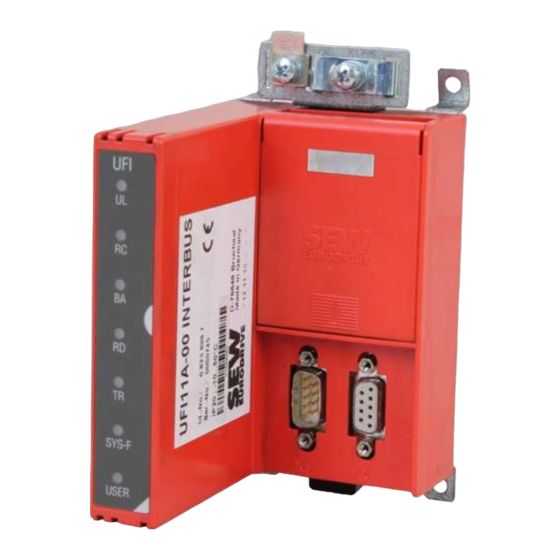
Page 5: Unit Structure
INTERBUS remote out (outgoing remote bus) DIP switches Logic voltage Incoming remote bus OK Bus mode active Outgoing remote bus switched off Parameter data exchange via PCP channel SYS-F System fault USER Expert mode Manual – Fieldbus Interface INTERBUS UFI11A... -
Page 6: Installation And Operation With Autosetup
Fig. 3: Pinout of the 9-pin sub D male connector X3 to EN 50170 ([1] = 9-pin sub D male connector; [2] = Signal lines twisted pair; [3] = Conductive connection between the connector housing and the shield) Manual – Fieldbus Interface INTERBUS UFI11A... - Page 7 7 and 2 (/DI and DI). Communication takes place via these contacts. The RS-485 signals /DO and DO as well as /DI and DI must have the same contacts on all INTER- BUS stations. Otherwise, communication via the bus will not function. Manual – Fieldbus Interface INTERBUS UFI11A...
- Page 8 –Capacitance per unit length ≤ 40 pF/m (12 pF/ft) at 1 kHz • The permitted total cable length depends on the baud rate setting of the SBus: –250 kbaud: 160 m (528 ft) –500 kbaud: 80 m (264 ft) –1000 kbaud: 40 m (132 ft) Manual – Fieldbus Interface INTERBUS UFI11A...
- Page 9 In the event of fluctuations in the ground potential, a compensating current may flow along the shield which is connected at both ends and to the ground potential (PE). In this case, make adequate provision for equipotential bonding in accordance with the rele- vant VDE regulations. Manual – Fieldbus Interface INTERBUS UFI11A...
-
Page 10: Setting The Inverter Parameters
Autosetup if no inverter is detected. In this case, check the cabling of the SBus, the terminating resistors of the SBus, the voltage supply to the inverters and the SBus address settings (P813). Manual – Fieldbus Interface INTERBUS UFI11A... -
Page 11: Configuring The Fieldbus Master
Assign program addresses of the control program to the INTERBUS process data of the inverters. This assignment takes place via the context menu "Process data" or "Process data manager." • Enhance the control program by the data exchange with the UFI11A. Manual – Fieldbus Interface INTERBUS UFI11A... -
Page 12: Starting The Inverters
Fig. 6: Data exchange INTERBUS master – UFI11A – inverter You can enable the inverter by writing the value 0006h in the corresponding control word. You can enter the speed setpoint in the following word; it is scaled with 0.2 1/min per digit. Manual – Fieldbus Interface INTERBUS UFI11A... -
Page 13: Installation And Operation With A Pc
Fig. 7: Pinout of the 9-pin sub D male connector X3 to EN 50170 ([1] = 9-pin sub D male connector; [2] = Signal lines twisted pair; [3] = Conductive connection between the connector housing and the shield) Manual – Fieldbus Interface INTERBUS UFI11A... - Page 14 7 and 2 (/DI and DI). Communication takes place via these contacts. The RS-485 signals /DO and DO as well as /DI and DI must have the same contacts on all INTER- BUS stations. Otherwise, communication via the bus will not function. Manual – Fieldbus Interface INTERBUS UFI11A...
- Page 15 –Capacitance per unit length ≤ 40 pF/m (12 pF/ft) at 1 kHz • The permitted total cable length depends on the baud rate setting of the SBus: –250 kbaud: 160 m (528 ft) –500 kbaud: 80 m (264 ft) –1000 kbaud: 40 m (132 ft) Manual – Fieldbus Interface INTERBUS UFI11A...
- Page 16 In the event of fluctuations in the ground potential, a compensating current may flow along the shield which is connected at both ends and to the ground potential (PE). In this case, make adequate provision for equipotential bonding in accordance with the rele- vant VDE regulations. Manual – Fieldbus Interface INTERBUS UFI11A...
-
Page 17: Pc Connection
Save the project data and press the "Download“ button. If you experience problems with the download, you have probably set the DIP switch to AUTOSETUP. You need to turn off the autosetup feature when configuring with a PC. Manual – Fieldbus Interface INTERBUS UFI11A... -
Page 18: Configuring The Fieldbus Master
Assign program addresses of the control program to the INTERBUS process data of the inverters. This assignment takes place via the context menu "Process data" or "Process data manager." • Enhance the control program by the data exchange with the UFI11A. Manual – Fieldbus Interface INTERBUS UFI11A... -
Page 19: Starting The Inverters
UFx Configurator. You can enable the inverter by writing the value 0006h in the corresponding control word. You can enter the speed setpoint in the following word; it is scaled with 0.2 1/min per digit. Manual – Fieldbus Interface INTERBUS UFI11A... -
Page 20: Interbus Interface
CMD tool. In this mode, you will have to enter the ID code, process data channel and device type according to Fig. 11. 05654AXX Fig. 11: Off-line configuration with the CMD Tool Manual – Fieldbus Interface INTERBUS UFI11A... - Page 21 11 process data words (Param + 11PD) 218 Bit 13 process data words (Param + 13 PD) 240 Bit 15 process data words (Param + 15 PD) 368 Bit 23 process data words (Param + 23 PD) Manual – Fieldbus Interface INTERBUS UFI11A...
- Page 22 You can initially install the INTERBUS system completely and then set the DIP switches of the UFI11A. The entire bus structure (configuration frame) can then be read in via the CMD Tool. All stations will be automatically identified with their set data length. Manual – Fieldbus Interface INTERBUS UFI11A...
- Page 23 INTERBUS interface module (Fig. 12) with a management PC from the management level. 05655AXX Fig. 12: Device description for UFI Select "Remote Bus" as interface type. Manual – Fieldbus Interface INTERBUS UFI11A...
- Page 24 ".\IBSCMD\Pict32\" (Fig. 13) for easier identification of the drive inverter. You will find the "INTERBUS description files for CMD Tool" under "Software / Movitrac" on the SEW homepage at http://www.SEW-EURODRIVE.com. 03716AXX Fig. 13: Linking device description with ICO files Manual – Fieldbus Interface INTERBUS UFI11A...
- Page 25 You assign the INTERBUS process data of the drive inverters to the program addresses cess data of the control system with the context menu "Process Data." 05657AXX Fig. 15: Assignment of INTERBUS process data and PLC program addresses Manual – Fieldbus Interface INTERBUS UFI11A...
- Page 26 Click on the UFI to which you would like to establish a PCP connection. Open the con- text menu with the right mouse button and select the menu item "Device Parameteriza- tion". Fig. 17: Testing the PCP device parameterization Manual – Fieldbus Interface INTERBUS UFI11A...
- Page 27 Repeat the configu- ration of the interface module and the sequence for testing the PCP connection. 03713AXX Fig. 19: CMD Tool reads in device parameters, indicating that the PCP communication is ok Manual – Fieldbus Interface INTERBUS UFI11A...
-
Page 28: Configuring The Interbus Interface
Fig. 21 shows an example setting of six process data words for two inverters. The value of each switch in determining the process data length is shown on the right. 05377AXX Fig. 21: Process data words Manual – Fieldbus Interface INTERBUS UFI11A... - Page 29 Note that if the total of process data and PCP words exceeds 10 words, you must select a value equal to or greater than your required data length from the following settings: 0 – 10 words set directly, 12 words, 14 words, 16 words, 24 words and 26 words. Manual – Fieldbus Interface INTERBUS UFI11A...
- Page 30 De-energize the UFI11A before adjusting the DIP switch settings. The settings of DIP switches S1-1 to S1-7 are only read during the power-up initialization. The UFI11A signals the "Microprocessor not ready" ID code (38h) if the settings of DIP switches S1-1 to S1-7 are invalid. Manual – Fieldbus Interface INTERBUS UFI11A...
-
Page 31: Examples Of Dip Switch Settings For Process Data And Pcp Communication In Autosetup Mode
6 process data words are set. 0, 1, 2 and 4 PCP words can be set using DIP switches (6 process data PCP1 and PCP2. words) 3 inverters 9 process data words are set. 0 and 1 PCP word can be set using DIP switches PCP1 (9 process data and PCP2. words) Manual – Fieldbus Interface INTERBUS UFI11A... - Page 32 15 process data words are set. Only 1 PCP word can be set using DIP switches PCP1 (15 process data and PCP2. words) 6 inverters 20 process data words are set. 4 PCP words must be set using DIP switches PCP1 and (18 process data PCP2. words) Manual – Fieldbus Interface INTERBUS UFI11A...
- Page 33 22 process data words are set. 2 and 4 PCP words can be set using DIP switches PCP1 (21 process data and PCP2. words) 8 inverters 24 process data words are set. 0 and 2 PCP words can be set using DIP switches PCP1 (24 process data and PCP2. words) Manual – Fieldbus Interface INTERBUS UFI11A...
-
Page 34: Control Via Interbus
PI 1 PIW314 PI 3 PIW312 PI 2 PIW310 PIW308 PI 1 50394AXX Fig. 23: Representation of the INTERBUS data in the PLC address area ([1] = PLC address area / U/f = Inverter) Manual – Fieldbus Interface INTERBUS UFI11A... -
Page 35: Pcp Interface
• Establishing the connection (Initiate) • Reading of parameter values (Read) • Writing of parameter values (Write) • Cancelling the connection (Abort) 05389AXX Fig. 24: PCP services supported by the UFI11A fieldbus interface Manual – Fieldbus Interface INTERBUS UFI11A... - Page 36 UFI11A. All objects in the static object list are addressed using indices. The following table shows the structure of the object list of the UFI11A. Manual – Fieldbus Interface INTERBUS UFI11A...
- Page 37 Index: 8300 ... 8313 Object code: 7 (simple variable) Data type index : 10 (octet string) Length: Local address: Password: Access groups: Access rights: Read all/Write all Name[16]: Extension length: Manual – Fieldbus Interface INTERBUS UFI11A...
- Page 38 1. Initiate the service coded in the parameter channel by means of a WRITE to the "MOVILINK parameter channel cyclical" object. WRITE 8288 (parameter channel) Service confirmation (OK/error code) The WRITE service coded in the parameter channel is performed and the service con- firmation is returned directly as the response. Manual – Fieldbus Interface INTERBUS UFI11A...
- Page 39 Index: 8288 Object code: 11 (string variable) Data type index : 10 (octet string) Length: Local address: Password: Access groups: Access rights: Read all/Write all Name[16]: Extension length: Manual – Fieldbus Interface INTERBUS UFI11A...
- Page 40 Index: 8296 Object code: 7 (simple variable) Data type index : 10 (octet string) Length: Local address: Password: Access groups: Access rights: Write all Name[16]: Extension length: Manual – Fieldbus Interface INTERBUS UFI11A...
- Page 41 8299 "MOVILINK parameter channel acyclical" if the parameters of the UFI11A are to be addressed. Index: 8297 Object code: 7 (simple variable) Data type index : 10 (octet string) Length: Local address: Password: Access groups: Access rights: Read all Name[16]: Extension length: Manual – Fieldbus Interface INTERBUS UFI11A...
- Page 42 1. Initiate the service coded in the parameter channel by means of a WRITE to the "MOVILINK parameter channel cyclical" object. WRITE 8299 (parameter channel) Service confirmation (OK/error code) The WRITE service coded in the parameter channel is performed and the service con- firmation is returned directly as the response. Manual – Fieldbus Interface INTERBUS UFI11A...
- Page 43 Index: 8299 Object code: 7 (simple variable) Data type index : 10 (octet string) Length: Local address: Password: Access groups: Access rights: Read all/Write all Name[16]: Extension length: Manual – Fieldbus Interface INTERBUS UFI11A...
-
Page 44: Return Codes For Parameter Setting
Error code = 0 (other error code) is the only error code that has been defined for error class 8 = Other error. You will find detailed information for this error in "Additional code." Manual – Fieldbus Interface INTERBUS UFI11A... - Page 45 Code (dez) Meaning Error class: Access Error code: Hardware problem Add. code high: Add. code low: Manual – Fieldbus Interface INTERBUS UFI11A...
-
Page 46: Autosetup
UFI11A, because the UFI11A saves these values once only during Autosetup. Likewise, the process data assignments (P860 ... P865) of the connected inverters must not be altered dynamically either, for example by an IPOS pro- gram, following Autosetup. Manual – Fieldbus Interface INTERBUS UFI11A... - Page 47 INTERBUS Interface 05431AXX Fig. 25: Data exchange INTERBUS master – UFI11A – inverter Manual – Fieldbus Interface INTERBUS UFI11A...
-
Page 48: Error Response
1 of all inverters. The SYS-FLT LED on the UFI11A then flashes evenly. The exact error code is displayed in the status of the UFI11A using the diagnostic interface of MOVITOOLS. Manual – Fieldbus Interface INTERBUS UFI11A... -
Page 49: Diagnostic Leds
BUS has been stopped display of the INTERBUS interface module (master) for additional error localization. LED RD "Remote Bus Disable" Status Meaning Remedy (red) Outgoing remote bus turned off Outgoing remote bus not turned off Manual – Fieldbus Interface INTERBUS UFI11A... - Page 50 SBus as well as the inverter voltage supply. Reconfigure the UFI11A with MOVITOOLS if necessary. LED "USER" (green) Statuts Meaning Standard operating status. The "USER“ LED is reserved for expert mode. Manual – Fieldbus Interface INTERBUS UFI11A...
-
Page 51: Dip Switches
If you require a number of words which lies between these settings, the next higher num- ber must be used. For example, 9PD + 4 words PCP results in 14 words. AUTO SETUP: See Sec. Quickstart without PC Manual – Fieldbus Interface INTERBUS UFI11A... -
Page 52: Application Examples
You should have access to the following user manuals: • INTERBUS user manual "Peripherals Communication Protocol (PCP)", PHOENIX CONTACT, IBS SYS PCP G4 UM • Manual for the fieldbus unit profile of the drive inverter connected to the UFI11A Manual – Fieldbus Interface INTERBUS UFI11A... -
Page 53: Representation Of The Coding Examples
Comm._Reference 00 02 Password Access_Groups 00 00 Bits 15 ... 8 7 ... 0 After sending the service, you should receive a confirmation with "Initiate_Confirmation" (see PCP manual in case of a non-confirming message). Manual – Fieldbus Interface INTERBUS UFI11A... -
Page 54: Reading Of An Ufi Parameter
Data [4] = Low Byte 00 hex 28 hex 01 hex 00 hex 00 28 01 00 hex = Identification for UFI11A You will find additional information on the UFI11A parameters in the section "Parameter List." Manual – Fieldbus Interface INTERBUS UFI11A... -
Page 55: Writing Of Ufi11A Or Drive Parameters Via Object 8288
Data[12] 23 45 Bits 15 ... 8 7 ... 0 After sending this service, you will receive the "Write_Confirmation." You can once again use the return codes for the evaluation of a negative message. Manual – Fieldbus Interface INTERBUS UFI11A... -
Page 56: Reading Of Ufi11A Or Drive Parameters Via Object 8288
"Write_Request" into the interface module. Word Meaning Coding (hex) Command_Code = Read_Request 00 81 Parameter_Count 00 03 Invoke_ID Comm._Reference 00 02 Index = 8288 20 60 Subindex 00 00 Bits 15 ... 8 7 ... 0 Manual – Fieldbus Interface INTERBUS UFI11A... - Page 57 You can use the return codes for the evaluation of negative messages. Word Meaning Coding (hex) Command_Code = Read_Confirmation 80 81 Parameter_Count 00 03 Invoke_ID Comm._Reference 00 02 Error_Class Error_Code 08 00 Additional_Code 00 10 Bits 15 ... 8 7 ... 0 Manual – Fieldbus Interface INTERBUS UFI11A...
-
Page 58: Parameter List
IPOS PO DATA Setpoint description PO3 8306 IPOS PO DATA Acutal value description PI1 8307 IPOS PI DATA Actual value description PI2 8308 IPOS PI DATA Actual value description PI3 8309 IPOS PI DATA Manual – Fieldbus Interface INTERBUS UFI11A... -
Page 59: List Of Errors
Perform reset. Contact SEW Service for advice if problem persists. Invalid IPOS IPOS program Attempt was made to set an invalid Check write values of external control word stopped automatic mode (via external cont- control rol). Manual – Fieldbus Interface INTERBUS UFI11A... - Page 60 An error occurred while the data Carry out the "delivery condition" cation stopped record was being copied. The data factory setting, perform a reset and are not consistent. then try to copy the data again. Manual – Fieldbus Interface INTERBUS UFI11A...
-
Page 61: Technical Data
Ambient temperature: -10 °C...+50 °C SBus Maximum transmission speed: 1 MBaud Transfer protocol: MOVILINK Number of units on SBus: max. 8 Process data words per unit: max. 3 PD Connection technology: Disconnectable screw terminals Manual – Fieldbus Interface INTERBUS UFI11A... -
Page 62: Dimensions
Dimensions Dimensions 05114AXX Fig. 27: Dimension drawing Manual – Fieldbus Interface INTERBUS UFI11A... -
Page 63: Index
Initiate 36 Shielding 7, 8, 9, 14, 15, 16 Installation notes 6, 13 Starting the inverters 12, 19 Internal communication error 45 Startup 10, 17, 20 Inverter parameters 10, 17 Subchannel 38 SYS-FAULT 50 Manual – Fieldbus Interface INTERBUS UFI11A... - Page 64 Unit structure 5 UWS21A 17 Variable data channel with acyclical routing object Write 35, 36, 38, 42 Write parameter values 35, 36, 38, 42 Writing of UFI11A or drive parameters via object 8288 55 Manual – Fieldbus Interface INTERBUS UFI11A...
- Page 68 SEW-EURODRIVE GmbH & Co · P.O. Box 3023 · D-76642 Bruchsal/Germany · Phone +49-7251-75-0 Fax +49-7251-75-1970 · http://www.sew-eurodrive.com · sew@sew-eurodrive.com...
Need help?
Do you have a question about the INTERBUS UFI11A and is the answer not in the manual?
Questions and answers