Table of Contents
Advertisement
INSTRUCTION:
INTEGRATION GUIDE FOR SILICON LABS ZENGECKO Z-WAVE® DEVICES
The purpose of this document is to provide an implementation guide for integrating Z-Wave 700 devices into product designs.
It is intended for product design engineers who aim for a fast integration of Z-Wave 700 devices.
1
OVERVIEW
The Z-Wave 700 device portfolio is shown in Table 1.1. The EFR32ZG14 gateway SoC exposes the Z-Wave serial API via UART and
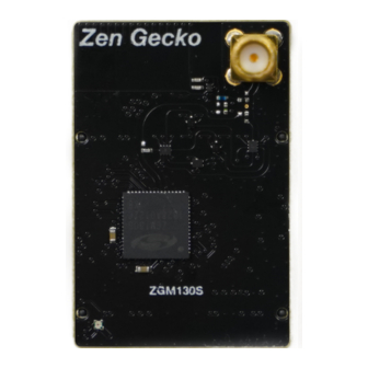
is dedicated to gateway applications. The ZGM130S SiP module combines a general-purpose SoC, crystal, supply decoupling
components, and RF matching components into a single small-footprint module requiring only two decoupling capacitors. The
ZGM130S is targeted at end device applications and, with its built-in ARM M4 core and ultra-low power consumption, it is perfect
for making single chip sensors and other end devices that require advanced processing and low power consumption.
Type
Chip
Module
The applicable modules are clearly stated at the beginning of each of the following sections.
INS14487-3 | 2/2019
Z-Wave 700 Integration Guide
Table 1.1: Z-Wave 700 device portfolio
QFN32
SoC
5mm x 5mm
EFR32ZG14
LGA64
SiP
9mm x 9mm
ZGM130S
1
Advertisement
Table of Contents

Related Manuals for Silicon Laboratories Z-WAVE 700


Summary of Contents for Silicon Laboratories Z-WAVE 700
-
Page 1: Overview
It is intended for product design engineers who aim for a fast integration of Z-Wave 700 devices. OVERVIEW The Z-Wave 700 device portfolio is shown in Table 1.1. The EFR32ZG14 gateway SoC exposes the Z-Wave serial API via UART and is dedicated to gateway applications. The ZGM130S SiP module combines a general-purpose SoC, crystal, supply decoupling components, and RF matching components into a single small-footprint module requiring only two decoupling capacitors. -
Page 2: Table Of Contents
Instruction: Z-Wave Z-Wave 700 Integration Guide CONTENT OVERVIEW..................................1 PROGRAMMING AND DEBUGGING INTERFACE ........................3 ............................4 ROGRAMMING INTERFACE OVERVIEW CALIBRATION..................................4 ....................................4 RYSTAL RF VERIFICATION TOOL ..............................4 COMPONENT SPECIFICATIONS ............................4 SAW F ....................................4 ILTER 6.1.1 Recommended Components for GSM/LTE gateways ....................6 6.1.2 OPTIONAL Components for GSM/LTE gateways......................6 ....................................6... -
Page 3: Programming And Debugging Interface
Applicable A programming interface is mandatory if In-System Programming of a Z-Wave 700 device is required, i.e., programming while soldered onto the product PCB. To design in a footprint for the Mini Simplicity header, Silicon Labs recommends using a small 10- pin 1.27 mm SMD header for both programming and debugging of chips from the Silicon Labs Gecko family. -
Page 4: Programming Interface Overview
Applicable It is recommended that a SAW filter is used in Z-Wave 700 gateway designs also containing GSM or LTE transceivers operating in the subGHz band. A SAW filter attenuates unwanted radio emissions and improves the receiver blocking performance. Three... - Page 5 Instruction: Z-Wave 700 Integration Guide regions are defined to cover the global Z-Wave frequency range. The SAW filter specifications described in Table 6.1, Table 6.2, and Table 6.3 are recommended for new designs. Table 6.1: Region E Frequency Range Unit...
-
Page 6: Recommended Components For Gsm/Lte Gateways
The crystal is part of the oscillator that generates the reference frequency for the digital system clock and RF carrier. It is a critical component of a Z-Wave 700 device. Further, it is mandatory to calibrate the crystal for gateway designs. Refer to section 4 for more information. -
Page 7: Recommended Components
For Z-Wave 700 devices, the filter shown in Figure 7.1 is strongly recommended. For normal scenarios, this will provide adequate filtering with a low BOM cost. -
Page 8: Mandatory Components
Instruction: Z-Wave Z-Wave 700 Integration Guide L103 VDCDC C107 C106 BLM03AX241SN1D 220N EFR32ZG14 LFD21868MMF5E233 RF Crystal RF I/O HFXTAL_N SUBGRF_OP SUBGRF_IP 50R_RF_OUT HFXTAL_P GND1 RF Analog Power SUBGRF_IN GND2 RFVDD GND3 SUBGRF_ON GND4 Ground Sub-GHz RFVSS matching network Figure 8.1: Recommended RF matching component for the EFR32ZG14 gateway SoC: Murata LFD21868MMF5E233 IPD 8.1.1 MANDATORY COMPONENTS... -
Page 9: Measurement Setup
When measuring the sensitivity, first measure and record the output power of the Z-Wave frame generator using the spectrum analyzer. A Z-Wave 700 module programmed with the RailTest tool can be used as the Z-Wave frame generator. Then a fixed attenuator can be used along with a variable attenuator to adjust the input power of the DUT. -
Page 10: Pcb Implementation
SAW filter as close as possible to the RF pin of the EFR32ZG14 It is strongly recommended that the Z-Wave 700 device is placed close to a corner of the PCB, away from any high frequency switching circuits. -
Page 11: Decoupling
AVDD and one on VDD and VDDIO combined. Figure 9.5: Recommended external supply decoupling for the ZGM130S 9.4.2 FOR EFR32ZG14 GATEWAY SOC For Z-Wave 700 devices with only the digital supply, the filter shown in Figure 9.6 is strongly recommended. INS14487-3 | 2/2019... -
Page 12: Rf Trace
Instruction: Z-Wave Z-Wave 700 Integration Guide EFR32ZG14 VDCDC Reset DC/DC Regulator L100 RADIO_#RESET EFR32ZG14 RESETn High Frequency VREGSW Crystal VMCU C115 RF Crystal RF I/O Digital Supply HFXTAL_N SUBGRF_OP Digital Regulator VREGVDD SUBGRF_IP VMCU C110 C111 39.000 MHz DVDD Analog Supply... -
Page 13: Ic Grounding
Applicable Applicable Since ESD can destroy the Z-Wave 700 product, great care must be taken during manufacturing and assembly of final goods to avoid ESD. By design, all pins of EFR32ZG14 and ZGM130S are ESD protected up to a level of 2.5 kV HBM. -
Page 14: Abbreviations
Instruction: Z-Wave Z-Wave 700 Integration Guide 12 ABBREVIATIONS Abbreviation Description 2FSK 2-key Frequency Shift Keying 2GFSK 2-key Gaussian Frequency Shift Keying Abstract Control Model ACMA Australian Communications and Media Authority Analog-to-Digital Converter Advanced Encryption Standard Application Programming Interface Auto Programming Mode... - Page 15 Instruction: Z-Wave 700 Integration Guide Abbreviation Description International Telecommunications Union JEDEC Joint Electron Device Engineering Council Light-Emitting Diode Low-Noise Amplifier Local Oscillator Least Significant Bit Least Significant Byte Microcontroller Unit Ministry of Internal affairs and Communications, Japan MISO Master In, Slave Out...
-
Page 16: Revision History
2018/12/4 P. 4, 6, 14 Updated based on comments from NTJ and MHANSEN 2018/12/4 §All Table 6.6 added and all references to devices corrected to ‘Z-Wave 700’ 2018/12/5 P. 18 Legal disclaimer updated based on Silabs disclaimer from AN961 2018/12/5 Front page Corrected title to "Z-Wave 700 Integration Guide"... -
Page 17: References
Instruction: Z-Wave 700 Integration Guide 14 REFERENCES Silicon Labs, “Silicon Labs Production Programming Options”, AN136 Silicon Labs, “Instruction for Bring-up/test HW development”, INS14283 Silicon Labs, “AN972: EFR32 RF Evaluation Guide”, AN972 Silicon Labs, “Instruction for Mandatory crystal adjustment for EFR32ZG14 based products”, INS14498... - Page 18 TRADEMARKS Silicon Laboratories Inc.® , Silicon Laboratories®, Silicon Labs®, SiLabs® and the Silicon Labs logo®, Z-Wave®, Z-Wave Logo®, Bluegiga®, Bluegiga Logo®, Clockbuilder®, CMEMS®, DSPLL®, EFM®, EFM32®, EFR, Ember®, Energy Micro, Energy Micro logo and combinations thereof, "the world’s most energy friendly microcontrollers", Ember®, EZLink®, EZRadio®, EZRadioPRO®, Gecko®,...
Need help?
Do you have a question about the Z-WAVE 700 and is the answer not in the manual?
Questions and answers