Table of Contents
Advertisement
Quick Links
UG508: EFR32FG23 Dev Kit User's Guide
The EFR32FG23 Dev Kit is a low cost, small form factor prototyp-
ing and development platform for the EFR32FG23 Wireless Sys-
tem-on-Chip.
The board is small, cost effective, and feature rich. It is an ideal platform for developing
energy-friendly connected IoT devices based on the EFR32FG23.
A built in SEGGER J-Link debugger ensures easy debugging through the USB Micro-B
connector.
silabs.com | Building a more connected world.
TARGET DEVICE
• EFR32FG23 Wireless System-on-Chip
(EFR32FG23B010F512IM48)
• 32-bit ARM® Cortex®-M33 with 78 MHz
maximum operating frequency
• 512 kB flash and 64 kB RAM
• Energy-efficient radio core with low
active and sleep currents
• Integrated PA with up to 20 dBm (sub-
GHz) TX power
• Robust peripheral set and 31 GPIO
KIT FEATURES
• SMA connector for antenna connection
• 5-digit 7-segment LCD
• Relative humidity and temperature sensor
• LC sensor for metal detection
• User LED and 2 push buttons
• 2.54 mm breakout pads for GPIO access
• SEGGER J-Link on-board debugger
• Virtual COM port
• Packet Trace Interface (PTI)
• Mini Simplicity connector for AEM and
packet trace using external Silicon Labs
debugger
• USB or coin cell battery powered.
SOFTWARE SUPPORT
• Simplicity Studio™
ORDERING INFORMATION
• FG23-DK2600A
Rev. 1.1
Advertisement
Table of Contents

Related Manuals for Silicon Laboratories EFR32FG23


Summary of Contents for Silicon Laboratories EFR32FG23
- Page 1 UG508: EFR32FG23 Dev Kit User's Guide The EFR32FG23 Dev Kit is a low cost, small form factor prototyp- TARGET DEVICE ing and development platform for the EFR32FG23 Wireless Sys- tem-on-Chip. • EFR32FG23 Wireless System-on-Chip (EFR32FG23B010F512IM48) The board is small, cost effective, and feature rich. It is an ideal platform for developing •...
-
Page 2: Table Of Contents
3.2 Power Supply ......8 3.3 EFR32FG23 Reset ......8 3.4 Peripherals . - Page 3 5.5.2 Recommendations for 915 MHz FCC 15.247 compliance ....23 6. Schematics, Assembly Drawings, and BOM ....24 7.
-
Page 4: Introduction
• 1x 915 MHz antenna (Chilisin BTEA0019130G9R2A01). • 1x USB Type A to Micro-B cable. 1.2 Getting Started Detailed instructions for how to get started with your new EFR32FG23 Dev Kit can be found on the Silicon Labs web pages: https://www.silabs.com/dev-tools 1.3 Hardware Content The following key hardware elements are included on the EFR32FG23 Dev Kit: •... -
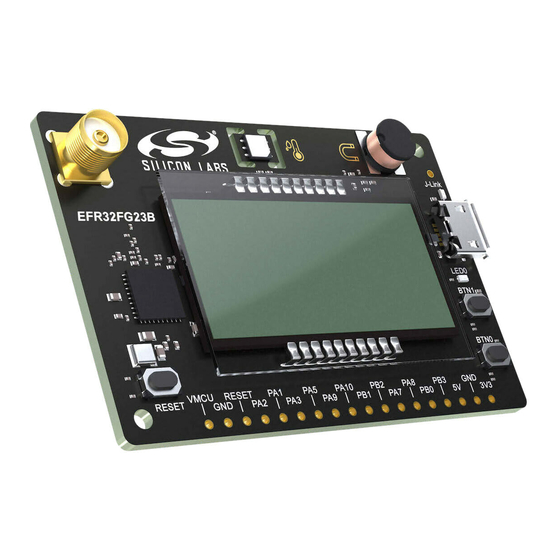
Page 5: Kit Hardware Layout
UG508: EFR32FG23 Dev Kit User's Guide Introduction 1.4 Kit Hardware Layout The layout of the EFR32FG23 Dev Kit is shown below. Humidity and LC Sensor Temperature Sensor On-board USB J-Link Debugger SMA Antenna Connector USB Micro-B Connector - Virtual COM port... -
Page 6: Specifications
UG508: EFR32FG23 Dev Kit User's Guide Specifications 2. Specifications 2.1 Recommended Operating Conditions The following table is intended to serve as guideline for a correct use of EFR32FG23 Dev Kit, indicating typical operating conditions and some design limits. Table 2.1. Recommended Operating Conditions Parameter... -
Page 7: Hardware
UG508: EFR32FG23 Dev Kit User's Guide Hardware 3. Hardware The core of the EFR32FG23 Dev Kit is the EFR32FG23 Wireless SoC. The board also contains several peripherals connected to the EFR32FG23. Placement and layout of the hardware components are described in section 1.4 Kit Hardware Layout. -
Page 8: Power Supply
VMCU net. It is important to follow this in order to avoid power conflicts and backfeeding the battery. Powering the EFR32FG23 Dev Kit through the Mini Simplicity connector allows current measurements using the Advanced Energy Monitoring (AEM) as described in section 4.2 External... -
Page 9: Peripherals
3.4.1 Segment LCD A 20-pin segment LCD is connected to the EFR32FG23's LCD peripheral. The LCD has 4 common lines and 10 segment lines, giving a total of 40 segments. These lines are not shared on the breakout pads. Refer to the kit schematic for information on signals to seg- ments mapping. -
Page 10: Push Buttons And Led
The button connections are shown in the figure below. The kit also features one yellow LED, marked LED0. The LED is controlled by a GPIO pin on the EFR32FG23 in an active-high configu- ration. The LED connection is shown in the figure below. -
Page 11: Connectors
3.6 Connectors Featured on the EFR32FG23 Dev Kit is a Mini Simplicity Connector, a USB Micro-B connector and 20 breakout pads that follow the EXP header pinout. The connectors are placed on the top side of the board, and their placement and pinout can be seen in the figure below. -
Page 12: Breakout Pads
18 breakout pads are located on the bottom edge of the board. These allow connection of peripherals or add-on boards. The breakout pads expose I/O pins that can be used with most of the EFR32FG23's features. Additionally, VMCU (main power rail), 3V3 (USB regu- lator output) and 5V power rails are also exposed. -
Page 13: Mini Simplicity Connector
Silicon Labs Wireless Starter Kit (WSTK) mainboard. See section 4.2 External Debugger for more details. The pinout of the con- nector on the board is described in the table below with the names being referenced from the EFR32FG23. Table 3.3. Mini Simplicity Connector Pin Descriptions Pin number... -
Page 14: Debugging
4.2 External Debugger. When using an external debugger it is very important to make sure that there is no power source present on the EFR32FG23 Dev Kit, as the external debugger might source a voltage on the target power domain (VMCU). -
Page 15: On-Board Debugger
4.3 Virtual COM Port The virtual COM port (VCOM) is a connection to a UART on the EFR32FG23, and allows serial data to be sent and received from the device. The on-board debugger presents this as a virtual COM port on the host computer that shows up when the USB cable is inser- ted. -
Page 16: Radio
5.1.1 Description of the Sub-GHz RF Matching The EFR32FG23 has two TX outputs (SUBG_O0, SUBG_O1) and two RX inputs (SUBG_I0, SUBG_I1). The matching network con- nects one of the TX outputs (SUBG_O0) and one of the RX inputs (SUBG_I0) to a single SMA connector while transforming the impe- dances to 50 Ohms. -
Page 17: Rf Matching Bill Of Materials
UG508: EFR32FG23 Dev Kit User's Guide Radio 5.1.3 RF Matching Bill of Materials The Bill of Materials of the BRD2600A RF matching network is shown in the following table. Table 5.1. Bill of Materials of the BRD2600A RF Matching Network... -
Page 18: Fcc15.247 Emission Limits For The 902-928 Mhz Band
UG508: EFR32FG23 Dev Kit User's Guide Radio 5.2.2 FCC15.247 Emission Limits for the 902-928 MHz Band FCC 15.247 allows conducted output power up to 1 Watt (30 dBm) in the 902-928 MHz band. For spurious emmissions the limit is -20 dBc based on either conducted or radiated measurement, if the emission is not in a restricted band. The restricted bands are speci- fied in FCC 15.205. - Page 19 UG508: EFR32FG23 Dev Kit User's Guide Radio 5.4.1.1 Conducted Measurements in the 868 MHz Band The typical output spectrum is shown in the following figure. Figure 5.2. Typical Output Spectrum of the BRD2600A at 868 MHz with 14 dBm output power As shown in the figure above, the fundamental is around 14 dBm, so it is under the ETSI limit of 16.1 dBm.
- Page 20 UG508: EFR32FG23 Dev Kit User's Guide Radio 5.4.1.2 Conducted Measurements in the 915 MHz Band The typical output spectrum is shown in the following figure. Figure 5.3. Typical Output Spectrum of the BRD2600A at 915 MHz with 14 dBm output power As shown in the figure above, the fundamental is around 14 dBm, so it is under the FCC limit of 30.0 dBm.
-
Page 21: Radiated Power Measurements
UG508: EFR32FG23 Dev Kit User's Guide Radio 5.4.2 Radiated Power Measurements During the radiated measurements, the BRD2600A board was supplied through its USB connector by connecting to a PC through a USB cable. The supply for the RF section (RFVDD) and the power amplifier (PAVDD) was 1.8 V provided by the on-chip DCDC con- verter. - Page 22 UG508: EFR32FG23 Dev Kit User's Guide Radio 5.4.2.2 Radiated Measurements in the 915 MHz Band For the 915 MHz radiated power measurements, an external whip antenna (Chilisin BTEA0019130G8R2A01) was used as a transmitter antenna. It was connected to the on-board SMA connector.
-
Page 23: Emc Compliance Recommendations
UG508: EFR32FG23 Dev Kit User's Guide Radio 5.4.2.4 Antenna Pattern Measurement in the 915 MHz Band The measured typical antenna patterns are shown in the figures below. Normalized Radiation Pattern [dB], 915 MHz, XY Normalized Radiation Pattern [dB], 915 MHz, XZ Normalized Radiation Pattern [dB], 915 MHz, YZ 0°... -
Page 24: Schematics, Assembly Drawings, And Bom
UG508: EFR32FG23 Dev Kit User's Guide Schematics, Assembly Drawings, and BOM 6. Schematics, Assembly Drawings, and BOM Schematics, assembly drawings, and bill of materials (BOM) are available through Simplicity Studio when the kit documentation pack- age has been installed. They are also available from the kit page on the Silicon Labs website: http://www.silabs.com/. -
Page 25: Kit Revision History
UG508: EFR32FG23 Dev Kit User's Guide Kit Revision History 7. Kit Revision History The kit revision can be found printed on the box label of the kit, as outlined in the figure below. The kit revision history is summarized in the table below. -
Page 26: Board Revision History And Errata
UG508: EFR32FG23 Dev Kit User's Guide Board Revision History and Errata 8. Board Revision History and Errata 8.1 Board Revision History The board revision can be found laser printed on the back side of the board. Table 8.1. BRD2600A Revision History... -
Page 27: Document Revision History
UG508: EFR32FG23 Dev Kit User's Guide Document Revision History 9. Document Revision History Revision 1.1 September, 2021 • Fixed image for Fig. 5.1. • Fixed RF pin names in section 5.1.1. Revision 1.0 September, 2021 • Initial document version. silabs.com | Building a more connected world. - Page 28 Note: This content may contain offensive terminology that is now obsolete. Silicon Labs is replacing these terms with inclusive language wherever possible. For more information, visit www.silabs.com/about-us/inclusive-lexicon-project Trademark Information Silicon Laboratories Inc. , Silicon Laboratories , Silicon Labs , SiLabs...
Need help?
Do you have a question about the EFR32FG23 and is the answer not in the manual?
Questions and answers