Table of Contents
Advertisement
Quick Links
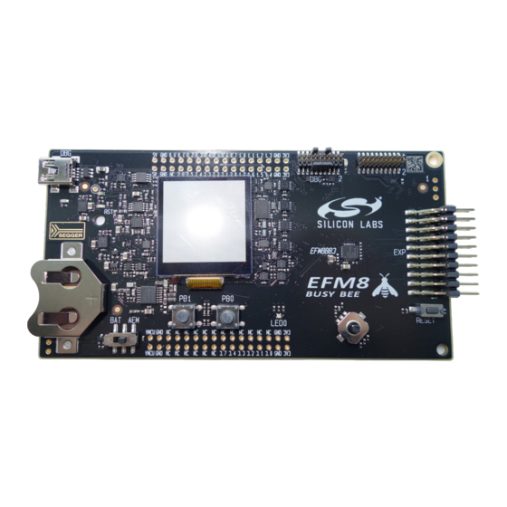
UG125: EFM8BB3-SLSTK2022A User's
Guide
The EFM8BB3-SLSTK2022A is an excellent starting point to get
familiar with the EFM8 Busy Bee microcontrollers.
The kit contains sensors and peripherals demonstrating some of the MCU's many capa-
bilities. The kit can also serve as a starting point for application development.
The kit includes the following:
• EFM8BB3 Busy Bee Starter Kit Board
• 1 x CR2032 battery
silabs.com | Building a more connected world.
• Getting Started card
• 1 x mini USB cable
KEY FEATURES
• EFM8BB31F64G MCU with 64 KB Flash
and 4 KB RAM.
• 20-pin expansion header.
• Power sources include USB and CR2032
battery.
• 2 user buttons, 1 tri-color LED.
• 8-direction joystick.
• Ultra low power 128x128 pixel Memory-
LCD.
Rev. 0.7
Advertisement
Table of Contents

Related Manuals for Silicon Laboratories EFM8BB3-SLSTK2022A


Summary of Contents for Silicon Laboratories EFM8BB3-SLSTK2022A
- Page 1 UG125: EFM8BB3-SLSTK2022A User's Guide The EFM8BB3-SLSTK2022A is an excellent starting point to get familiar with the EFM8 Busy Bee microcontrollers. KEY FEATURES • EFM8BB31F64G MCU with 64 KB Flash The kit contains sensors and peripherals demonstrating some of the MCU's many capa- and 4 KB RAM.
-
Page 2: Getting Started
UG125: EFM8BB3-SLSTK2022A User's Guide Getting Started 1. Getting Started For information on getting started with the EFM8BB3-SLSTK2022A kit, including links to documentation and other resources, visit the kit product page. Hardware To set up the hardware for the EFM8BB3-SLSTK2022A kit: 1. - Page 3 UG125: EFM8BB3-SLSTK2022A User's Guide Kit Block Diagram 2. Kit Block Diagram An overview of the EFM8BB3 Starter Kit is shown in the figure below. Board EFM8BB3 Controller Microcontroller Joystick Figure 2.1. Kit Block Diagram silabs.com | Building a more connected world.
-
Page 4: Kit Hardware Layout
Joystick Buttons User LED Figure 3.1. EFM8BB3-SLSTK2022A Hardware Layout The EFM8 device on the kit is connected to several peripherals. The table below shows all of the external connections to the MCU. Table 3.1. Kit MCU Connections MCU Port Pin... - Page 5 UG125: EFM8BB3-SLSTK2022A User's Guide Kit Hardware Layout MCU Port Pin Port Pin Assigned Primary Board Connec- Secondary Board Con- Expansion Port Con- Function tion nection nection (EXP) P1.7 ADC / CMP Joystick P2.0 UART1 TX UART1 TX EXP12 P2.1 UART1 RX...
-
Page 6: Power Supply And Reset
Power Supply and Reset 4. Power Supply and Reset 4.1 MCU Power Selection The Busy Bee MCU on the EFM8BB3-SLSTK2022A is designed to be powered by three different sources: • Through the on-board debugger. • By a 3 V battery. - Page 7 UG125: EFM8BB3-SLSTK2022A User's Guide Peripherals 5. Peripherals The starter kit has a set of peripherals that showcase some of the features of the EFM8 Busy Bee microcontroller. Be aware that most EFM8 I/O routed to peripherals are also routed to the breakout pads. This must be taken into consideration when using the breakout pads for your application.
- Page 8 UG125: EFM8BB3-SLSTK2022A User's Guide Peripherals 5.2 Joystick The kit has an analog joystick with 8 measureable positions. This joystick is connected to the EFM8 on the P1.7 pin and uses different resistor values to create voltages measurable by the ADC0.
- Page 9 UG125: EFM8BB3-SLSTK2022A User's Guide Peripherals 5.3 Memory LCD-TFT Display A 1.28-inch SHARP Memory LCD-TFT has been added to the board to enable interactive applications to be developed. The display has a high resolution of 128 by 128 pixels and consumes very little power. It is a reflective monochrome display, so each pixel can only be light or dark, and no backlight is needed in normal daylight conditions.
- Page 10 UG125: EFM8BB3-SLSTK2022A User's Guide Connectors 6. Connectors 6.1 Breakout Pads Many of the EFM8's pins are routed out to "breakout pads" at the top and bottom edges of the kit. A 2.54 mm pitch pin header can be soldered in for easy access to these pins. Most I/O pins are available, with the exception of pins used to drive the LCD.
- Page 11 UG125: EFM8BB3-SLSTK2022A User's Guide Connectors 6.2 Expansion Header On the right hand side of the board an angled 20-pin expansion header is provided to allow connection of peripherals or plugin boards. The connecter contains a number of I/O pins that can be used with most of the Busy Bee's features. Additionally, the VMCU, 3V3 and 5V power rails are also exported.
- Page 12 UG125: EFM8BB3-SLSTK2022A User's Guide Connectors Note: This table only sums up some of the alternate functions available on the expansion header. Consult the EFM8BB31F64G data sheet for a complete list of alternate functions. 6.3 Debug Connector This connector is used for Debug In and Debug Out (see chapter on Debugging).
- Page 13 UG125: EFM8BB3-SLSTK2022A User's Guide Connectors 6.4 Direct Debug Connector This connector (J103) is used for directly debugging the EFM8 using an external debug adapter (see chapter on Debugging). This is especially useful for debugging the MCU on the STK board when the part is battery powered or powered by an external supply.
-
Page 14: Advanced Energy Monitor
UG125: EFM8BB3-SLSTK2022A User's Guide Advanced Energy Monitor 7. Advanced Energy Monitor 7.1 Usage The AEM data is collected by the board controller and can be displayed by the energyAware Profiler, available through Simplicity Stu- dio. By using the energyAware Profiler, current consumption and voltage can be measured in realtime. - Page 15 UG125: EFM8BB3-SLSTK2022A User's Guide Board Controller 8. Board Controller The kit contains a board controller that is responsible for performing various board-level tasks, such as handling the debugger and the Advanced Energy Monitor. An interface is provided between the EFM8 and the board controller in the form of a UART connection. The connection is enabled by setting the EFM_BC_EN (P2.2) line high, and using the lines EFM_BC_TX (P0.4) and EFM_BC_RX (P0.5) for...
- Page 16 9. Debugging The EFM8BB3-SLSTK2022A contains an integrated debugger, which can be used to download code and debug the Busy Bee EFM8 MCU. In addition to programming the MCU on the kit, the debugger can also be used to program and debug external Silicon Labs EFM8 devices.
-
Page 17: Kit Configuration And Upgrades
UG125: EFM8BB3-SLSTK2022A User's Guide Kit Configuration and Upgrades 10. Kit Configuration and Upgrades The kit configuration dialog in Simplicity Studio allows you to change the J-Link adapter debug mode, upgrade its firmware, and change other configuration settings. To download Simplicity Studio, go to http://www.silabs.com/simplicity. -
Page 18: Schematics, Assembly Drawings, And Bom
UG125: EFM8BB3-SLSTK2022A User's Guide Schematics, Assembly Drawings, and BOM 11. Schematics, Assembly Drawings, and BOM The schematics, assembly drawings, and bill of materials (BOM) for the EFM8BB3 Starter Kit board are available through Simplicity Studio when the kit documentation package has been installed. -
Page 19: Revision History
UG125: EFM8BB3-SLSTK2022A User's Guide Revision History 12. Revision History Revision 0.7 September, 2020 • Updated 11.1 Board Revision History for Rev A05 • Updated the AEM section. Revision 0.6 February, 2019 • Updated 11.1 Board Revision History for Rev A04 Revision 0.5... - Page 20 Trademark Information Silicon Laboratories Inc.®, Silicon Laboratories®, Silicon Labs®, SiLabs® and the Silicon Labs logo®, Bluegiga®, Bluegiga Logo®, ClockBuilder®, CMEMS®, DSPLL®, EFM®, EFM32®, EFR, Ember®, Energy Micro, Energy Micro logo and combinations thereof, “the world’s most energy friendly microcontrollers”, Ember®, EZLink®, EZRadio®, EZRadioPRO®, Gecko®, Gecko OS, Gecko OS Studio, ISOmodem®, Precision32®, ProSLIC®, Simplicity Studio®, SiPHY®, Telegesis, the Telegesis Logo®, USBXpress®, Zentri, the Zentri logo and...
Need help?
Do you have a question about the EFM8BB3-SLSTK2022A and is the answer not in the manual?
Questions and answers