Kessel EasyClean free Auto Mix Manual
Hide thumbs
Also See for EasyClean free Auto Mix:
- Instructions for installation, operation and maintenance (124 pages) ,
- Disposal instructions (2 pages)
Table of Contents
Advertisement
Available languages
Available languages
Quick Links
Einbau- und Betriebsanleitung
DE
........................................................................................................................ 2
EN
...................................................................................................................... 23
FR
...................................................................................................................... 45
IT
...................................................................................................................... 67
NL
...................................................................................................................... 89
PL
.................................................................................................................... 111
2020/06
EasyClean free
Auto Mix
016-188_01
Advertisement
Chapters
Table of Contents

Related Manuals for Kessel EasyClean free Auto Mix


Summary of Contents for Kessel EasyClean free Auto Mix
- Page 1 EasyClean free Auto Mix Einbau- und Betriebsanleitung ........................2 ........................23 ........................45 ........................67 ........................89 ........................111 2020/06 016-188_01...
-
Page 2: Table Of Contents
Liebe Kundin, lieber Kunde, als Premiumhersteller von innovativen Produkten für die Entwässerungstechnik bietet KESSEL ganzheitliche Systemlösun- gen und kundenorientierten Service. Dabei stellen wir höchste Qualitätsstandards und setzen konsequent auf Nachhaltig- keit - nicht nur bei der Herstellung unserer Produkte, sondern auch im Hinblick auf deren langfristigen Betrieb setzen wir uns dafür ein, dass Sie und Ihr Eigentum dauerhaft geschützt sind. -
Page 3: Hinweise Zu Dieser Anleitung
Hinweise zu dieser Anleitung Folgende Darstellungskonventionen erleichtern die Orientierung: Darstellung Erläuterung Positionsnummer 5 von nebenstehender Abbildung Handlungsschritt in Abbildung Prüfen, ob Handsteuerung aktiviert wurde. Handlungsvoraussetzung OK betätigen. Handlungsschritt ✓ Anlage ist betriebsbereit. Handlungsergebnis Querverweis auf Kapitel 2 siehe "Sicherheit", Seite 4 Bildschirmtext |Wartungsintervall definieren| Fettdruck... -
Page 4: Sicherheit
Sicherheit Allgemeine Sicherheitshinweise WARNUNG Spannungsführende Teile Bei Tätigkeiten an elektrischen Leitungen und Anschlüssen Folgendes beachten. Für alle Anschlüsse und Installations-Arbeiten an der Anlage gelten nationale Vorschriften zur elektrischen Sicherheit. Die Anlage muss über eine Fehlerstrom-Schutzeinrichtung (RCD) mit einem Bemessungsfehlerstrom von nicht mehr als 30mA versorgt werden. - Page 5 Person freigegebene Tätigkeiten an KESSEL-Anlagen Betreiber Sichtprüfung Sachkundiger (kennt, ver- Entleerung, Rei- steht Betriebsanweisung) nigung (innen), Funktionskontrolle Fachkundiger (Fach- Einbau, Tausch, handwerker, nach Ein- Wartung von bauanweisung und Komponenten, Ausführungsnormen) Inbetriebnahme Generalinspekteur Dichtheitsprüfung, Über- (gemäß EN 1825) prüfung der korrekten...
-
Page 6: Technische Daten
Technische Daten Maße und Gewichte Außenabmessungen a (mm) l (mm) b (mm) b1 (mm) h1 (mm) h2 (mm) h3 (mm) h4 (mm) 1500 1735 1055 1435 1765 1500 1735 1055 1435 1765 1880 2115 1055 1435 1765 1910 2145 1130 1185 1255 1655... - Page 7 Angabe Wert Erforderlicher Fehlerstromschutz (RCD) 30 mA Förderhöhe max. 17 m Förderleistung max. 60 m Förderguttemperatur (dauerhaft) max. 40 °C Anzugsdrehmoment Beschreibung / Verwendung Drehmoment Nm Schlüsselweite PT-Schraube KB60x30 WN 1411 4,5 ±0,5 PT-Schraube 100x30 A2 Befestigungsschelle (Fülleinrichtung) ISK 10mm Rohrschelle D=120 8-10 Nuss 13mm...
-
Page 8: Montage
Montage Transporthinweis Zur leichteren Einbringung kann die Pumpe und die Verrohrung demontiert werden. Nach Wiederanbringung der Pumpe und der Verrohrung muss eine Dichtheitsprüfung durchgeführt werden. Transport mit Gabelstapler! Beim Transport mit einem Gabelstapler sollte die Pumpe an den Rohrschellen der Spülleitung und der Verbindung zum Behälter demontiert werden, um starke Belastung auf den Schweißnähten an der Verbindung der Pumpe zum Behälter zu vermeiden. - Page 9 Rohrleitungen montieren Zu- und Auslauf anschließen Anschluss von Zu- und Auslauf an bauseitiges Entwässe- rungssystem. Sollen die Anschlüsse gegenseitig getauscht werden, diese jeweils zusammen mit den Schrauben (1) und Dichtungen (2) demontieren und entsprechend tau- schen. Sicherstellen, dass die Dichtungen (3) ausrei- chend gefettet sind.
- Page 10 Schaltgerät montieren WARNUNG Anlage freischalten! Sicherstellen, dass Leitungen und elektrische Komponenten während der Arbeiten von der Spannungsversorgung getrennt sind. Das Schaltgerät kann nur geöffnet werden, wenn sich der Hauptschalter in Position OFF befindet. Schrauben am Gehäusedeckel lösen und Gehäusedeckel aufklappen. Gehäuse am vorgesehenen Ort montieren, dazu alle vier Befestigungsmöglichkeiten in den Ecken des Gehäuses ver- wenden.
- Page 11 Elektrische Anschlüsse herstellen Anschlussplan Netz (400 V AC 50Hz) Pumpe (400 V AC 50Hz) Magnetventil Warmwasser (230 V AC, 50 Hz, stromlos geschlossen) Magnetventil Kaltwasser (230 V AC, 50 Hz, stromlos geschlossen) Potentialfreier Kontakt (Warnung) Potentialfreier Kontakt (Störung) Fernbedienung Schaltgerät anschließen Geeignete Position zum Anbringen des Schaltgerätes auswählen.
- Page 12 USB-Anschluss herausführen Damit der USB-Anschluss auf der Platine ohne ein Öffnen des Gehäuses zugänglich wird, kann eine USB-Gehäusebuchse mit Kabel und Stecker zum Einbau in das Gehäuse des Schaltgerätes bei KESSEL bestellt werden (Art. Nr. 28785). Potentialfreier Kontakt (optionales Zubehör) Sofern gewünscht, können Signalgeber oder weiteres Zubehör als potentialfreie Kontakte (42 V 0,5 A) angeschlossen wer-...
-
Page 13: Inbetriebnahme
Funktionsprüfung durchführen, siehe unten. Wird eine automatische Ausschaltung des Füllvorgangs gewünscht, kann dies mit der automatischen Wassernachspei- sung KESSEL-EasyFill (Art. Nr. 919010) realisiert werden. Legionellenvorsorge Prüfen, ob die Leitungsführung eine regelmäßige Legionellenspülung erforderlich macht. Falls ja, die Länge der betroffe- nen Leitung ermitteln. - Page 14 Im Schaltgerät über navigieren (Passwort 1000). Dort im Menüpunkt | Einstellungen | | Parameter | die Häufigkeit der Spülung (jeweils morgens gegen 06:00 Uhr) in Tagen ein- Intervall Legionellenspülung | geben. Der voreingestellte Wert ist 0. Falls es die Leitungslänge erforderlich macht, die Dauer der Spülung anpassen. Menüpunkt | Legionellenspü- im selben Abschnitt des Menüs.
-
Page 15: Entsorgung
Entsorgung Entsorgung durchführen Abpumpen starten Saugschlauch des Entsorgungsfahrzeugs an Storz B Kupplung anschließen. Abpumpvorgang des Entsorgungsfahrzeugs starten. Teilentleeren Abwarten, bis 1/3 des Ruhepegels abgepumpt ist. Dauer ist abhängig von Nenngröße. Abpumpvorgang des Entsorgungsfahrzeugs pausieren. Schredder-Mix Pumpe einschalten. Abwarten, bis Abscheiderinhalt hinreichend homogeni- siert ist. - Page 16 Abpumpen stoppen Abpumpvorgang des Entsorgungsfahrzeugs beenden. Saugschlauch des Entsorgungsfahrzeugs von Storz B Kupplung lösen. Behälter auffüllen Abschluss des Programms mit OK bestätigen. Programm "Ventil Füllen" führt selbsttätig Kaltwasser zu, bis der Ruhepegel erreicht ist Ende des Entsorgungsvorgangs mit OK bestätigen. Entsorgung im Betriebstagebuch protokollieren.
-
Page 17: Wartung
Wartung Intervall Generalinspektion An dieser Anlage muss gemäß DIN EN 1825 alle 5 Jahre eine Generalinspektion (u. a. Dichtheitsprüfung) durchgeführt werden. Wartungsintervall und -tätigkeiten Die Anlage ist jährlich durch einen Sachkundigen zu warten. Folgende Tätigkeiten sind im Rahmen der Wartung durchzuführen: Entsorgung durchführen. - Page 18 Hilfe bei Störungen Hilfe bei Störungen (Meldungen am Display) Störung Ursache Maßnahme(n) Drehfeldfehler Falsches Drehfeld bei Netzanschluss Drehfeld richtig anschließen. Motorschutz Motorschutzschalter hat ausgelöst Motorschutzschalter wieder einschalten. Stromwert Pumpe falsch eingestellt Einstellung im Menü |Anzahl Pum- anpassen. pen| Motorstrom aufgrund defekter oder blo- Pumpenwartung durchführen.
- Page 19 Hilfe bei Störungen (Pumpe) Störung Ursache Maßnahme(n) Pumpe läuft nicht an, zu geringe Leis- Motorschutzschalter hat ausgelöst Ausschalten und abwarten, bis Pumpe tung abgekühlt ist, dann erneut versuchen. Motor ist blockiert Blockade entfernen / Pumpe warten (Sicherheitshinweise beachten). Motor dreht zu schwer Netzanschluss auf Phasenausfall prü- fen.
-
Page 20: Übersicht Konfigurationsmenü
Übersicht Konfigurationsmenü Menütexte AutoMix Systeminfo Information Betriebsstunden 1.1.1 Gesamtlaufzeit 1.1.2 Laufzeit Pumpe 1.1.3 Anläufe Pumpe 1.1.4 Netzausfall Logbuch Steuerungstyp Wartungstermin 1.4.1 Letzte Wart. Abscheider 1.4.2 Nächste Wart. Abscheider Akt. Messwerte 1.5.1 Drehfeld Parameter 1.6.1 Reinigen+Schreddern 1.6.2 Ventil Teil-Füllen 1.6.3 Ventil Füllen 1.6.4 Einschaltverzögerung 1.6.5... - Page 21 3.4.4 2 Pumpen 6,5-8A Nenngröße 3.6.1 3.6.2 3.6.3 3.6.4 3.6.5 NS10 Sprache 3.8.1 Deutsch 3.8.2 English 3.8.3 Francais 3.8.4 Italiano 3.8.5 Nederlands 3.8.6 Polski Experten-Modus 3.9.1 Ein Verzögerung 3.9.2 Grenzlaufzeit 3.10 Rücksetzen 016-188_01 21 / 138...
-
Page 22: Werksabnahme, Prüfungen
Werksabnahme, Prüfungen Anlagenpass 22 / 138 016-188_01... - Page 23 Für Sie ist es wichtig, die Qualität und Funktionsfähigkeit Ihrer Anlage immer auf dem besten Stand zu halten, gerade wenn es um die Voraussetzung für eine Gewährleistung geht. Wenn Sie die Wartung über KESSEL durchführen lassen, gewähr- leisten wir Ihnen eine ständige Aktualisierung und Pflege Ihrer Anlage.
- Page 24 Dear customer, As a premium manufacturer of innovative products for draining technology, KESSEL offers integrated system solutions and customer-oriented service. In doing so, we set the highest quality standards and focus firmly on sustainability - not only with the manufacturing of our products, but also with regard to their long-term operation and we strive to ensure that you and your property are protected over the long term.
-
Page 25: Notes On This Manual
Notes on this manual The following conventions make it easier to navigate the manual: Symbol Explanation Position number 5 from the adjacent figure Action step in figure Check whether manual control has been Prerequisite for action activated. Press OK. Action step ✓... -
Page 26: Safety
Safety General safety notes WARNING Live parts Heed the following points when working on electrical cables and connections. The national regulations concerning electrical safety apply to all connections and installation work. The system must be supplied through a residual current protection device (RCD) with residual current of not more than 30mA. - Page 27 Person Approved activities on KESSEL systems Operating company Visual check Competent expert / Emptying, clean- inspector (familiar with, ing (inside), func- understands oper- tional check ating instructions) Competent skilled per- Installation, replace- son (specialist crafts- ment, maintenance man, in accordance with...
-
Page 28: Technical Data
Technical data Dimensions and weights External dimensions a (mm) l (mm) b (mm) b1 (mm) h1 (mm) h2 (mm) h3 (mm) h4 (mm) 1500 1735 1055 1435 1765 1500 1735 1055 1435 1765 1880 2115 1055 1435 1765 1910 2145 1130 1185 1255... - Page 29 Data Value Type of residual current device (RCD) required 30 mA Max. pumping height 17 m Max. pumping capacity 60 m (Permanent) temperature of conveyed material max. 40 °C Tightening torque Description / use Torque Nm Spanner size PT-screw KB60x30 WN 1411 4.5 ±0.5 PT-screw 100x30 A2 Attachment clamp (refill inlet)
-
Page 30: Installation
Installation Transport information The pump and the pipes can be dismantled for easier installation. A leak test must be performed after reattachment of the pump and the pipes. Transport by forklift truck! During transport by forklift truck the pump should be disconnected at the pipe clamps of the rinsing pipe and tank connection in order to avoid a heavy load on the weldseams at the connection between the pump and the tank. - Page 31 Installing the pipes Connect the inlet and outlet Connection of inlet and outlet to the draining system on site. If the connections are to be mutually swapped, remove them together with the screws (1) and seals (2) and swap them accordingly. Make sure that the seals (3) have been sufficiently lubricated.
- Page 32 Installing the control unit WARNING Disconnect system from energy sources! Make sure that cables and electrical components are disconnected from the power supply during work. The control unit can only be opened if the main switch is in the OFF position. Undo screws in the housing cover and lift up housing cover.
- Page 33 Establishing electrical connections Connection diagram Mains (400 V AC 50Hz) Pump (400 V AC 50Hz) Hot water solenoid valve (230 V AC, 50 Hz, closed when currentless) Cold water solenoid valve (230 V AC, 50 Hz, closed when currentless) Potential-free contact (warning) Potential-free contact (fault) Remote control Connecting the control unit...
- Page 34 To ensure that the USB connection on the printed board can be accessed without opening the housing, a USB housing socket with cable and connector for installation in the housing of the control unit can be ordered from KESSEL (art. no.
-
Page 35: Commissioning
Perform a functional test, see below. If automatic switching off of the filling process is required, this can be implemented using the automatic water refill device, KESSEL EasyFill (Art. No. 919010). Legionella prevention Check whether the routing requires regular legionella flushing. If yes, determine the length of the pipe concerned. - Page 36 In the control unit, navigate via (Password 1000). Then, in the | Settings | | Parameter | menu item, enter the flushing frequency (in the morning just before 06:00) Legionella flushing interval | in days. The preset value is 0. If the pipe length requires, adjust the flushing duration: menu item in the | Cold/hot legionella flushing|...
-
Page 37: Disposal
Disposal Carry out disposal Start pumping out Connect the suction hose of the disposal vehicle to the Storz-B coupling. Start the pumping process at the disposal vehicle. Partial emptying Wait until 1/3 of the static level has been pumped off. How long this takes depends on the nominal size. - Page 38 Stop pumping out End the pumping process at the disposal vehicle. Disconnect the suction hose of the disposal vehicle from the Storz-B coupling. Refilling the tank Confirm end of the program with OK. The "Fill valve” program adds cold water automatically, until the static level is reached Confirm end of the disposal process with OK.
-
Page 39: Maintenance
Maintenance Interval for general inspection A general inspection (including leak test) must be carried out on this system every 5 years in accordance with DIN EN 1825. Maintenance interval and tasks The system must be serviced annually by a competent expert / inspector. The following tasks are to be carried out during maintenance: Carry out disposal. - Page 40 Troubleshooting Help with faults (messages on the display) Fault Cause Action(s) Rotary field error Wrong rotary field for mains connection Connect rotary field correctly. Motor protection Motor protection switch has triggered Switch motor protection switch on again. Current value for pump not set cor- Adjust setting in the |Number of rectly...
- Page 41 Troubleshooting (pump) Fault Cause Action(s) Pump does not start up, power too low Motor protection switch has triggered Switch off and wait until the pump has cooled down then try again. Motor is blocked Remove blockage / service the pump (heed the safety instructions).
-
Page 42: Overview Of Configuration Menu
Overview of configuration menu AutoMix menu texts System info Information Hours of operation 1.1.1 Total running time 1.1.2 Run time pump 1.1.3 Pump starts 1.1.4 Power outage Log book Control type Maintenance date 1.4.1 Last separator maintenance 1.4.2 Next separator maintenance Current measured values 1.5.1 Rotary field... - Page 43 3.4.4 2 pumps 6.5-8A Nominal size 3.6.1 3.6.2 3.6.3 3.6.4 3.6.5 NS10 Language 3.8.1 Deutsch 3.8.2 English 3.8.3 Français 3.8.4 Italiano 3.8.5 Nederlands 3.8.6 Polski Expert mode 3.9.1 On delay 3.9.2 Max. run time 3.10 Reset 016-188_01 43 / 138...
-
Page 44: Factory Approval, Tests
Factory approval, tests System passport 44 / 138 016-188_01... - Page 45 For you, it is important that the quality and functional ability of your system is kept at the best possible standard, particularly when this is the pre-condition for warranty conditions. If you have the maintenance carried out by KESSEL, we guarantee you continued updating and care for your system.
- Page 46 Chère cliente, cher client, En qualité de producteur de pointe de produits novateurs dans le domaine de la technique d’assainissement, KESSEL pro- pose des réponses systématiques globales et un service orienté aux besoins de la clientèle. Nous misons simultanément sur les normes de qualité les plus élevées et une durabilité conséquente – non seulement lors de la fabrication de nos pro- duits, mais également pour leur utilisation à...
-
Page 47: Informations Spécifiques Aux Présentes Instructions
Informations spécifiques aux présentes instructions Les conventions de représentation suivantes facilitent l’orientation : Représentation Explication Numéro de repère 5 de la figure ci-contre Action de la figure Vérifier si la commande manuelle a été acti- Condition de réalisation de l’action vée. -
Page 48: Sécurité
Sécurité Consignes de sécurité générales AVERTISSEMENT Pièces sous tension Respecter les instructions suivantes lors de travaux sur des câbles et raccordements électriques. Les directives nationales de sécurité électrique s’appliquent à tous les raccordements et travaux d’installation sur le système. Le système doit être alimenté par un dispositif différentiel à courant résiduel (RCD) avec courant assigné de défaut d'une sensibilité... - Page 49 à la mise en pratique de formations se rappor- tant aux consignes de sécurité, d’empêcher toute personne non autorisée de l’utiliser. Personne Activités autorisées sur les postes KESSEL Exploitant Contrôle visuel Technicien spécialisé...
-
Page 50: Caractéristiques Techniques
Caractéristiques techniques Dimensions et poids Dimensions extérieures a (mm) l (mm) b (mm) b1 (mm) h1 (mm) h2 (mm) h3 (mm) h4 (mm) 1500 1735 1055 1435 1765 1500 1735 1055 1435 1765 1880 2115 1055 1435 1765 1910 2145 1130 1185 1255... - Page 51 Indication Valeur Protection différentielle requise (RCD) 30 mA Hauteur de relevage max. 17 m Capacité de refoulement max. 60 m Température du fluide refoulé (en continu) max. 40 °C Couple de serrage Description / utilisation Couple de rotation (Nm) Dimension de clé Vis PT KB60x30 WN 1411 4,5 ±...
-
Page 52: Montage
Montage Remarque relative au transport Il est possible de démonter la pompe et la tuyauterie pour faciliter la mise en place. Il convient de procéder à un essai d'étanchéité après le remontage de la pompe et de la tuyauterie. Transport avec chariot élévateur ! En cas de transport avec un chariot élévateur, il est nécessaire de démonter la pompe au niveau des colliers de la conduite de rinçage et du raccordement à... - Page 53 Montage de la canalisation Raccordement de l’arrivée et de la sortie Raccordement de l’arrivée et de la sortie sur le système d'évacuation sur site. S'il est nécessaire d'intervertir les raccordements, démonter les vis (1) et les joints (2) respectifs et les remonter en les permutant.
- Page 54 Montage du gestionnaire AVERTISSEMENT Activer le système ! S'assurer que les conduites et composants électriques sont coupés de l'alimentation en tension pendant les travaux. L'ouverture du gestionnaire n'est possible qu'à condition que l'interrupteur principal soit en position <OFF>. Desserrer les vis du couvercle du boîtier et relever le couvercle du boîtier. Monter le boîtier à...
- Page 55 Réalisation des raccordements électriques Schéma de raccordement Secteur (400 V AC /50 Hz) Pompe (400 V AC 50 Hz) Électrovanne eau chaude (230 V AC, 50 Hz, normalement fermée) Électrovanne eau froide (230 V AC, 50 Hz, normalement fermée) Contact sec (avertissement) Contact sec (dysfonctionnement) Télécommande Raccordement du gestionnaire...
- Page 56 Afin que le port USB situé sur la platine soit aussi accessible sans l'ouverture du boîtier, il est possible de commander un boîtier à douille USB, équipé d'un câble et d'un connecteur, à intégrer dans le boîtier du gestionnaire chez KESSEL (réf.
-
Page 57: Mise En Service
Effectuer un contrôle fonctionnel, voir ci-dessous. Si un arrêt automatique du processus de remplissage est souhaité, celui-ci peut être réalisé avec la réalimentation d’eau automatique EasyFill de KESSEL (réf. 919010). Prévention des légionelles Vérifier si le tracé de la conduite requiert un contrôle régulier des légionelles. Si cela est le cas, déterminer la longueur de la conduite concernée. - Page 58 Dans le gestionnaire, aller au menu choisir ensuite (mot de passe | Configurations | | Paramètres | 1000). Saisir sous le point de menu | Intervalle rinçage de prévention de la prolifération la fréquence du rinçage (le matin vers 6h) en jours. La valeur par défaut est définie sur 0. des légionelles | Adapter la durée du rinçage si la longueur de la conduite le requiert.
-
Page 59: Évacuation
Évacuation Procéder à l’évacuation Démarrer le pompage. Raccorder le tuyau d’aspiration du véhicule de pompage et de vidange au dispositif d’accouplement Storz B. Démarrer le pompage sur le véhicule. Vidange partielle Patienter jusqu’au refoulement d’1/3 du niveau de repos. La durée dépend de la taille nominale. Interrompre le pompage sur le véhicule. - Page 60 Démarrer le pompage. Confirmer la fin du processus d'évacuation en appuyant sur OK. Redémarrer le pompage sur le véhicule. Patienter jusqu’à ce que la cuve soit entièrement pompée (bruit d'aspiration). Stopper le pompage. Arrêter le pompage sur le véhicule de pompage et de vidange.
-
Page 61: Maintenance
Maintenance Intervalle pour l’inspection générale Il est nécessaire de procéder à une inspection générale (et notamment à un essai d'étanchéité) de ce poste tous les 5 ans conformément à la norme DIN EN 1825. Intervalles et opérations de maintenance Demander à un technicien de procéder annuellement à l'entretien du poste. Les opérations suivantes doivent être réalisées dans le cadre de la maintenance : Procéder à... - Page 62 Aide en cas de panne Aide en cas de panne (messages affichés à l’écran) Dysfonctionnement Cause Solution(s) Défaut du champ magnétique rotatif Raccordement erroné du champ Raccorder correctement le champ magnétique rotatif magnétique rotatif. Protection du moteur Déclenchement du disjoncteur de pro- Réactiver le disjoncteur de protection du tection du moteur moteur.
- Page 63 Aide en cas de panne (pompe) Dysfonctionnement Cause Solution(s) La pompe ne démarre pas, puissance Déclenchement du disjoncteur de pro- Désactiver la pompe et attendre que la trop faible tection du moteur pompe refroidisse puis essayer de nou- veau. Blocage du moteur Éliminer le blocage / procéder à...
-
Page 64: Aperçu Du Menu De Configuration
Aperçu du menu de configuration Textes menu AutoMix Info système Information Heures de service 1.1.1 Durée totale 1.1.2 Durée de marche de la pompe 1.1.3 Démarrages de la pompe 1.1.4 Panne de secteur Journal Type de commande Date de maintenance 1.4.1 Dernière maintenance du sépa- rateur... - Page 65 3.1.5 Rinçage froid de prévention de la prolifération des légionelles 3.1.6 Rinçage froid de prévention de la prolifération des légionelles 3.1.7 Rinçage chaud de prévention de la prolifération des légio- nelles 3.1.30 Emprise de RemoteControl Mémoire 3.2.1 Enregistrement des paramètres 3.2.2 Chargement des paramètres Date / Heure...
-
Page 66: Réception En Usine, Contrôles
Réception en usine, contrôles Fiche système 66 / 138 016-188_01... - Page 67 à KESSEL. Êtes-vous à la recherche d'un contrat de maintenance ou d'une offre relative à l'inspection générale ? Veuillez copier cette page et nous la renvoyer complétée à dienstleistung@kessel.de ou veuillez remplir le formulaire de contact sous www.kes- sel.de/service/dienstleistungen.
- Page 68 Cara cliente, caro cliente, in qualità di produttore premium di prodotti innovativi per la tecnica di drenaggio, KESSEL offre soluzioni di sistema integrate e un servizio orientato al cliente. Puntiamo sui massimi standard qualitativi e ci impegniamo coerentemente per la sosteni- bilità...
-
Page 69: Indicazioni Sulle Presenti Istruzioni
Indicazioni sulle presenti istruzioni Le seguenti convenzioni illustrative semplificano l’orientamento: Simbolo Spiegazione Posizione numero 5 della figura accanto Passaggio procedurale nella figura Controllare se il comando manuale è stato Presupposti per l’azione attivato. Premere OK. Passaggio procedurale ✓ L’impianto è pronto per funzionare. Risultato dell’azione Rimando al capitolo 2 vd. -
Page 70: Sicurezza
Sicurezza Avvertenze di sicurezza generali AVVERTENZA Parti conducenti tensione Per i lavori alle linee elettriche e ai collegamenti elettrici, tenere in considerazione quanto segue. Per tutti i lavori di collegamento e installazione sull’impianto trovano applicazione le norme nazionali sulla sicu- rezza elettrica. - Page 71 Persona Mansioni ammesse sugli impianti KESSEL Esercente Controllo visivo Esperto (conosce e com- Svuotamento, prende le istruzioni per l’uso) pulizia (all’inter- no), controllo di funzionamento Tecnico specializzato (arti- Installazione, giano specializzato nel sostituzione, rispetto delle istruzioni manutenzione di installazione e delle...
-
Page 72: Dati Tecnici
Dati tecnici Misure e pesi Misure esterne a (mm) l (mm) p (mm) b1 (mm) h1 (mm) a2 (mm) a3 (mm) h4 (mm) 1500 1735 1055 1435 1765 1500 1735 1055 1435 1765 1880 2115 1055 1435 1765 1910 2145 1130 1185 1255... - Page 73 Indicazione Valore Protezione da correnti di guasto necessaria (RCD) 30 mA Altezza di pompaggio massima 17 m Portata max. 60 m Temperatura del materiale trasportato (permanente) 40 °C max. Momento di serraggio Descrizione / Impiego Momento torcente N·m Apertura di chiave Vite PT KB60x30 WN 1411 4,5 ±0,5 Vite PT 100x30 A2...
-
Page 74: Montaggio
Montaggio Indicazione per il trasporto Per semplificare la consegna, la pompa e la tubazione possono essere smontate. Dopo il rimontaggio della pompa e della tubazione, è necessario effettuare una prova di tenuta. Trasporto con un carrello elevatore! In caso di trasporto con un carrello elevatore, la pompa dovrebbe essere smontata in corrispondenza delle staffe per tubi del condotto di spurgo e del collegamento al serbatoio, per evitare una sollecitazione eccessiva sulle saldature in corrispondenza del collegamento della pompa al serbatoio. - Page 75 Montaggio delle tubazioni Collegamento di entrata e uscita Collegamento di entrata e uscita al sistema di drenaggio presente sul posto. Se i collegamenti dovessero essere scambiati recipro- camente, questi dovrebbero essere smontati con le relative viti (1) e guarnizioni (2) ed essere quindi scam- biati adeguatamente.
- Page 76 Montaggio della centralina AVVERTENZA Disinserire l’impianto! Accertare che i cavi e i componenti elettrici siano separati dall’alimentazione di tensione durante i lavori. La centralina può essere aperta solo qualora l’interruttore principale si trovi in posizione OFF. Allentare le viti sul coperchio dell’alloggiamento e aprire il coperchio dell’alloggiamento. Montare l’alloggiamento nel luogo previsto;...
- Page 77 Creazione dei collegamenti elettrici Schema di collegamento Rete elettrica (400 V AC, 50 Hz) Pompa (400 V AC, 50 Hz) Elettrovalvola dell’acqua calda (230 V AC, 50 Hz, chiusa senza corrente) Elettrovalvola dell’acqua fredda (230 V AC, 50 Hz, chiusa senza corrente) Contatto a potenziale zero (avvertimento) Contatto a potenziale zero (disturbo) Telecomando...
- Page 78 Per fare in modo che il collegamento USB presente sul circuito stampato sia accessibile senza dover aprire l’alloggiamento è possibile ordinare presso KESSEL una presa USB per l’alloggiamento con cavo e connettore per l’installazione nell’allog- giamento della centralina (codice articolo 28785).
-
Page 79: Messa In Funzione
Eseguire il controllo di funzionamento, vedere sotto. Se si desidera la disattivazione automatica del procedimento di riempimento, questa può essere ottenuta con il rabbocco automatico dell’acqua EasyFill di KESSEL (codice articolo 919010). Prevenzione anti-legionella Controllare se il percorso dei condotti rende necessario uno spurgo anti-legionella regolare. In caso affermativo, determi- nare la lunghezza dei condotti interessati. - Page 80 Nella centralina, accedere a e quindi a (password 1000). Lì, nel punto | Impostazioni | | Parametri | del menù immettere la frequenza in giorni dello spurgo | Frequenza dello spurgo anti-legionella | (rispettivamente al mattino verso le ore 06:00). Il valore preimpostato è 0. Adeguare la durata dello spurgo se la lunghezza dei condotti lo rende necessario.
-
Page 81: Smaltimento
Smaltimento Esecuzione dello smaltimento Avvio del pompaggio di svuotamento Collegare il tubo flessibile di aspirazione del veicolo di smaltimento al giunto Storz B. Avviare il procedimento di pompaggio di svuotamento del veicolo di smaltimento. Svuotamento parziale Attendere fino a che non viene pompato via 1/3 del livello di quiete. - Page 82 Avvio del pompaggio di svuotamento Confermare la conclusione del procedimento di smalti- mento con OK. Riavviare il procedimento di pompaggio di svuotamento del veicolo di smaltimento. Attendere fino a che il serbatoio non è stato svuotato (rumore di risucchio). Arresto del pompaggio di svuotamento Concludere il procedimento di pompaggio di svuotamento del veicolo di smaltimento.
-
Page 83: Manutenzione
Manutenzione Frequenza dell’ispezione generale Questo impianto, a norma DIN EN 1825, deve essere sottoposto a un’ispezione generale (comprensiva di una prova di tenuta) ogni 5 anni. Frequenza e attività di manutenzione L’impianto deve essere manutenuto annualmente da un esperto. In occasione della manutenzione devono essere svolte le attività seguenti: Esecuzione dello smaltimento. - Page 84 Aiuto in caso di disturbi Aiuto in caso di disturbi (messaggi sul display) Disturbo Causa Misure Errore del campo rotante Campo rotante errato nel voltaggio Collegare correttamente il campo rotante. Salvamotore Il salvamotore è scattato Riaccendere il salvamotore. Valore di corrente della pompa impo- Adeguare le impostazioni nel menù...
- Page 85 Aiuto in caso di disturbi (pompa) Disturbo Causa Misure La pompa non si avvia, potenza insuffi- Il salvamotore è scattato Spegnere, attendere fino a che la ciente pompa non si è raffreddata e, quindi, riprovare. Il motore è bloccato Rimuovere il blocco/manutenere la pompa (rispettare le avvertenze di sicu- rezza).
-
Page 86: Visione D'insieme Del Menu Di Configurazione
Visione d’insieme del menu di configurazione Testi del menù AutoMix Informazioni di sistema Informazioni Ore di funzionamento 1.1.1 Tempo di funzionamento com- plessivo 1.1.2 Tempo di funzionamento della pompa 1.1.3 Avvii della pompa 1.1.4 Guasto alla rete elettrica Diario d’esercizio Tipo di comando Data di manutenzione 1.4.1... - Page 87 Memoria profilo 3.2.1 Salvataggio parametri 3.2.2 Caricamento parametri Data/Ora Numero di pompe 3.4.1 1 pompa 4-6,4 A 3.4.2 2 pompe 4-6,4 A 3.4.3 1 pompa 6,5-8 A 3.4.4 2 pompe 6,5-8 A Dimensioni nominali 3.6.1 3.6.2 3.6.3 3.6.4 3.6.5 NS10 Lingua 3.8.1 Deutsch...
-
Page 88: Collaudo Della Fabbrica, Controlli
Collaudo della fabbrica, controlli Scheda dell’impianto 88 / 138 016-188_01... - Page 89 Desiderate ricevere un’offerta relativa a un contratto di manutenzione o a un’ispezione generale? Vi preghiamo di copiare questa pagina e di inviarla compilata in ogni sua parte a dienstleistung@kessel.de o di compilare il modulo di richiesta alla pagina www.kessel.de/service/dienstleistungen.
- Page 90 Beste klant, Als premium fabrikant van innovatieve producten voor de afwateringstechniek biedt KESSEL totale systeemoplossingen en klantgerichte service. Wij stellen hierbij maximale kwaliteitsnormen en zetten consequent in op duurzaamheid, niet alleen bij de productie van onze producten, maar ook met het oog op hun langdurige gebruik zetten wij ons in voor een permanente bescherming van u en uw eigendom.
-
Page 91: Informatie Over Deze Handleiding
Informatie over deze handleiding De volgende weergaveconventies maken de oriëntatie eenvoudiger: Afbeelding Uitleg Positienummer 5 van nevenstaande afbeelding Handeling op de afbeelding … Controleren of de handbesturing is inge- Voorwaarde voor de handeling schakeld. Op OK drukken. Werkstap ✓ De installatie is bedrijfsklaar. Resultaat van de handeling Kruisverwijzing naar hoofdstuk 2 zie "Veiligheid", pagina 92... -
Page 92: Veiligheid
Veiligheid Algemene veiligheidsinstructies WAARSCHUWING Spanningvoerende delen Bij werkzaamheden aan de elektrische bekabeling en aansluitingen het onderstaande in acht nemen. Voor alle aansluitingen en installatiewerkzaamheden aan de installatie gelden nationale voorschriften voor elek- trische veiligheid. De installatie moet via een lekstroomvoorziening (RCD) met een nominale lekstroom van niet meer dan 30 mA worden gevoed. - Page 93 Persoon Vrijgegeven werkzaamheden bij KESSEL-installaties Exploitant Visuele inspectie Deskundige (kent en Lediging, reini- begrijpt gebruiksaanwijzing) ging (binnen- kant), controleren van de werking Vakkundige (vakman, vol- Inbouw, vervan- gens inbouwhandleiding ging, onderhoud en uitvoeringsnormen) van componenten, inbedrijfstelling Algemeen inspecteur Lektest, controle van...
-
Page 94: Technische Gegevens
Technische gegevens Maten en gewichten Buitenafmetingen a (mm) l (mm) b (mm) b1 (mm) h1 (mm) h2 (mm) h3 (mm) h4 (mm) 1500 1735 1055 1435 1765 1500 1735 1055 1435 1765 1880 2115 1055 1435 1765 1910 2145 1130 1185 1255 1655... - Page 95 Opgave Waarde Vereiste differentiaalbeveiliging (RCD) 30 mA Opvoerhoogte max. 17 m Opvoercapaciteit max. 60 m Temperatuur opvoermedium (permanent) max. 40 °C Aanhaalmoment Omschrijving/gebruik Aanhaalmoment Nm Sleutelmaat PT-schroef KB60x30 WN 1411 4,5 ± 0,5 PT-schroef 100x30 A2 Bevestigingsbeugel (vulvoorziening) ISK 10 mm Klemring D=120 8 - 10 kop 13 mm...
-
Page 96: Montage
Montage Transportinstructie De pomp en het leidingwerk kunnen worden gedemonteerd, zodat de installatie makkelijker kan worden geplaatst. Nadat de pomp en het leidingwerk weer zijn aangebracht, moet een lektest worden uitgevoerd. Transport met vorkheftruck! Bij transport met een vorkheftruck moet de pomp bij de buisklemmen van de spoelleiding en de verbinding met het reservoir worden gedemonteerd, zodat de lasnaden bij de verbinding van de pomp met het reser- voir niet te zwaar worden belast. - Page 97 Leidingen monteren Toevoer en uitloop aansluiten Het aansluiten van de toevoer en uitloop op het ontwate- ringssysteem van de inbouwlocatie. Als de aansluitingen wederzijds moeten worden omge- wisseld, moeten ze samen met de schroeven (1) en afdichtingen (2) worden gedemonteerd en ook worden omgewisseld.
- Page 98 Besturingskast monteren WAARSCHUWING Installatie loskoppelen! Waarborgen dat leidingen en elektrische componenten tijdens de werkzaamheden losge- koppeld zijn van de voedingsspanning. De besturingskast kan uitsluitend worden geopend als de hoofdschakelaar zich in stand OFF bevindt. Schroeven van de deksel van de behuizing losdraaien en deksel omhoog klappen. Behuizing op beoogde plaats monteren en daarbij alle vier de bevestigingsmogelijkheden in de hoeken gebruiken.
- Page 99 Elektrische aansluitingen maken Aansluitschema Stroomnet (400 V, 50 Hz wisselstroom) Pomp (400 V, 50 Hz wisselstroom) Magneetklep warm water (230 V, 50 Hz wisselstroom, stroomloos gesloten) Magneetklep koud water (230 V, 50 Hz wisselstroom, stroomloos gesloten) Potentiaalvrij contact (waarschuwing) Potentiaalvrij contact (storing) Afstandsbediening Besturingskast aansluiten Geschikte plek voor het plaatsen van de besturingskast...
- Page 100 USB-aansluiting naar buiten voeren Om toegang te krijgen tot de op de printplaat aanwezige USB-aansluiting zonder de behuizing te openen, kan bij KESSEL een USB-behuizingsbus met kabel en stekker voor inbouw in de behuizing van de besturingskast (zie art.nr. 28785) worden besteld.
-
Page 101: Inbedrijfstelling
Functiecontrole uitvoeren, zie hieronder. Als het vulproces automatisch moet kunnen worden uitgeschakeld, kan dit worden geregeld met het automatische vulsys- teem KESSEL-EasyFill (art.nr. 919010). Legionellamaatregelen Controleren of de uitvoering van de leidingen het nodig maakt om regelmatig legionellaspoelingen uit te voeren. In dat geval de lengte van de desbetreffende leiding vaststellen. - Page 102 Op de besturingskast via naar gaan (wachtwoord: 1000). Daar in het | Instellingen | | Parameters | menupunt instellen om de hoeveel dagen (altijd ’s morgens om 06.00 uur) | Interval legionellaspoeling | moet worden gespoeld. De voorgestelde waarde is 0. Als de lengte van de leiding hier aanleiding voor geeft de duur van het spoelen aanpassen.
-
Page 103: Lediging
Lediging Lediging uitvoeren Wegpompen starten Zuigslang van het ledigingsvoertuig aan de Storz-B-kop- peling aansluiten. De functie wegpompen op het ledigingsvoertuig starten. Deels legen Wachten tot een derde van het rustniveau is weg- gepompt. De duur is afhankelijk van de nominale grootte. - Page 104 Wegpompen stoppen De functie wegpompen op het ledigingsvoertuig beëindi- gen. Zuigslang van het ledigingsvoertuig van de Storz-B-kop- peling loskoppelen. Reservoir vullen Het afsluiten van het programma met OK bevestigen. Het programma “Ventiel vullen” voert zelfstandig koud water aan tot het rustniveau is bereikt. Het einde van het ledigingsproces met OK bevestigen.
-
Page 105: Onderhoud
Onderhoud Interval voor de algemene inspectie Deze installatie moet conform DIN EN 1825 elke vijf jaar een algemene inspectie (waaronder een lektest) ondergaan. Onderhoudsinterval en -werkzaamheden De installatie moet elk jaar door een deskundige worden onderhouden. Voor het onderhoud moeten de volgende handelingen worden uitgevoerd: Lediging uitvoeren. - Page 106 Hulp bij storingen Hulp bij storingen (meldingen op het scherm) Storing Oorzaak Maatregel(en) Fasefout Foutief draaiveld van de stroomaan- Fasen correct aansluiten. sluiting Motorbeveiliging Motorbeveiligingsschakelaar is geacti- Motorbeveiligingsschakelaar weer veerd inschakelen. Stroomwaarde pomp foutief ingesteld Instelling in het menu |Aantal pom- aanpassen.
- Page 107 Hulp bij storingen (pomp) Storing Oorzaak Maatregel(en) De pomp gaat niet aan, te weinig ver- Motorbeveiligingsschakelaar is geacti- Uitschakelen en wachten tot de pomp is mogen veerd afgekoeld, daarna opnieuw proberen. Motor is geblokkeerd Blokkade verwijderen / pomp onder- houden (veiligheidsinstructies in acht nemen).
-
Page 108: Overzicht Configuratiemenu
Overzicht configuratiemenu Menuteksten van AutoMix Systeeminfo Informatie Bedrijfsuren 1.1.1 Totale looptijd 1.1.2 Looptijd pomp 1.1.3 Starts pomp 1.1.4 Stroomuitval Logboek Besturingstype Onderhoudsdatum 1.4.1 Laatste onderh. Afscheider 1.4.2 Volgende onderh. Afscheider Act. meetwaarden 1.5.1 Fase Parameters 1.6.1 Reinigen+shredderen 1.6.2 Ventiel deels vullen 1.6.3 Ventiel vullen 1.6.4... - Page 109 3.4.4 2 pompen 6,5-8A Nominale grootte 3.6.1 3.6.2 3.6.3 3.6.4 3.6.5 NG10 Taal 3.8.1 Deutsch 3.8.2 English 3.8.3 Francais 3.8.4 Italiano 3.8.5 Nederlands 3.8.6 Polski Expertmodus 3.9.1 Aan vertraging 3.9.2 Grenslooptijd 3.10 Resetten 016-188_01 109 / 138...
-
Page 110: Acceptatietest, Controles
Acceptatietest, controles Installatiepaspoort 110 / 138 016-188_01... - Page 111 Het is belangrijk om te zorgen dat uw installatie altijd in goede staat blijft en goed blijft functioneren, vooral als dit een voor- waarde voor de fabrieksgarantie vormt. Als u het onderhoud door KESSEL wilt laat uitvoeren, garanderen wij u dat uw instal- latie permanent wordt geactualiseerd en onderhouden.
- Page 112 Szanowna Klientko, szanowny Kliencie! Jako producent najwyższej klasy innowacyjnych produktów z zakresu techniki odwadniania firma KESSEL oferuje komplek- sowe rozwiązania systemowe i serwis odpowiadający potrzebom klientów. Konsekwentnie stawiamy na jakość i trwałość rozwiązań. Nie tylko podczas produkcji naszych urządzeń, lecz również w zakresie ich długotrwałego użytkowania dbamy o to, by zagwarantowane było bezpieczeństwo użytkownika i jego mienia.
-
Page 113: Wskazówki Dotyczące Niniejszej Instrukcji
Wskazówki dotyczące niniejszej instrukcji Poniższe formy oznaczeń ułatwiają orientację: Oznaczenie Objaśnienie Numer pozycji 5 na rysunku obok Krok postępowania na rysunku Sprawdzić, czy aktywowane zostało stero- Warunek postępowania wanie ręczne. Nacisnąć przycisk OK. Krok postępowania ✓ Urządzenie jest gotowe do pracy. Wynik postępowania Odniesienie do rozdz. -
Page 114: Bezpieczeństwo
Bezpieczeństwo Ogólne zasady bezpieczeństwa OSTRZEŹENIE Elementy będące pod napięciem Podczas prac przy przewodach i przyłączach elektrycznych należy przestrzegać następujących wskazówek. Do wszystkich prac związanych z podłączaniem i instalacją na urządzeniu mają zastosowanie przepisy krajowe dot. bezpieczeństwa elektrycznego. Urządzenie musi posiadać wyłącznik różnicowoprądowy (RCD) o prądzie zadziałania nie większym niż 30 mA. PRZESTROGA Gorące powierzchnie! Silnik napędowy może podczas pracy nagrzać... - Page 115 Osoba Dozwolone czynności przy urządzeniach KESSEL Użytkownik Kontrola wzrokowa Osoba o odpowiednich Opróżnienie, czysz- kwalifikacjach (zna i rozu- czenie (wnętrza), mie instrukcję...
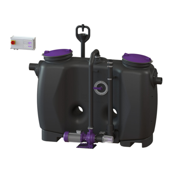
- Page 116 Nr poz. Komponenty Pompa „Schredder Mix” Przewód do płukania Dopływ Urządzenie sterujące z wyświetlaczem Otwór rewizyjny (od strony dopływu) Zawory elektromagnetyczne ciepłej i zimnej wody Urządzenie do napełniania Przewód do bezpośredniego opróżniania Otwór rewizyjny (od strony odpływu) (10) Odpływ (11) Zasuwa odcinająca do demontażu pompy (12) Punkty podnoszenia wózkiem widłowym (z...
-
Page 117: Dane Techniczne
Dane techniczne Masa i ciężary Wymiary zewnętrzne a (mm) l (mm) b (mm) b1 (mm) h1 (mm) h2 (mm) h3 (mm) h4 (mm) 1500 1735 1055 1435 1765 1500 1735 1055 1435 1765 1880 2115 1055 1435 1765 1910 2145 1130 1185 1255... - Page 118 Dane Wartość Wymagany bezpiecznik różnicowo-prądowy (RCD) 30 mA Maks. wysokość podnoszenia 17 m Maks. wydajność tłoczenia 60 m Temperatura tłoczonego medium (przy pracy stałej) maks. 40°C Moment dokręcenia Opis / zastosowanie Moment obrotowy Nm Rozmiar klucza Śruba PT KB60x30 WN 1411 4,5 ±0,5 Śruba PT 100x30 A2 Opaska mocująca (urządzenie do...
-
Page 119: Montaż
Montaż Wskazówka dotycząca transportu Aby ułatwić wstawienie urządzenia, można zdemontować pompę i orurowanie. Po ponownym podłączeniu pompy i oruro- wania należy dokonać badania szczelności. Transport wózkiem widłowym! Podczas transportu wózkiem widłowym należy zdemontować pompę przez zdjęcie zaci- sków rurowych przy przewodzie do płukania oraz odłączenie jej od zbiornika urządzenia, aby uniknąć obciążenia spoin w miejscu połączenia pompy ze zbiornikiem urządzenia. - Page 120 Montaż przewodów rurowych Podłączenie dopływu i odpływu Podłączenie dopływu i odpływu do systemu odwadniania budynku. W przypadku zamiany przyłączy należy je zdemon- tować razem ze śrubami (1) i uszczelkami (2) i odpo- wiednio zamienić. Upewnić się, że uszczelki (3) są wystarczająco nasmarowane.
- Page 121 Montaż urządzenia sterującego OSTRZEŹENIE Odłączyć urządzenie od prądu! Upewnić się, że przewody i komponenty elektryczne są na czas prac odłączone od zasilania napięciem. Urządzenie sterujące można otworzyć tylko wtedy, gdy wyłącznik główny jest ustawiony w pozycji OFF. Poluzować śruby w pokrywie urządzenia i rozłożyć pokrywę urządzenia. Zamontować...
- Page 122 Wykonanie połączeń elektrycznych Schemat połączeń Sieć (400 V AC, 50 Hz) Pompa (400 V AC, 50 Hz) Zawór elektromagnetyczny ciepłej wody (230 V AC, 50 Hz, bezprądowo zamknięty) Zawór elektromagnetyczny zimnej wody (230 V AC, 50 Hz, bezprądowo zamknięty) Kontakt bezpotencjałowy (ostrzeżenie) Kontakt bezpotencjałowy (zakłócenie) Pilot zdalnego sterowania Podłączenie urządzenia sterującego...
- Page 123 Zamontować modem TeleControl (nr art. 28792) według odpowiedniej instrukcji montażu 434-033. Wyprowadzenie portu USB Jeżeli port USB ma być dostępny bez konieczności otwarcia obudowy, można zamówić w firmie KESSEL gniazdo USB z kablem i wtyczką do zabudowy w obudowie urządzenia sterującego (nr art. 28785).
-
Page 124: Uruchomienie
Wykonać kontrolę działania, patrz na dole. Jeśli klient życzy sobie automatycznego wyłączenia procedury napełniania, jest to możliwe przy pomocy automatycznego systemu uzupełniania wody EasyFill KESSEL (nr art. 919010). Zapobieganie rozwojowi legionelli Sprawdzić, czy sposób poprowadzenia przewodów wymaga regularnego płukania w celu zapobiegnięcia rozwojowi legio- nelli. - Page 125 Przejść w urządzeniu sterującym poprzez menu do menu (hasło 1000). Tam w | Ustawienia | | Parametry | punkcie menu podać częstotliwość płukania | Odst#py mi#dzy p#ukaniami przeciwko legionelli | (ok. 06:00 rano) w dniach. Wstępnie ustawiona jest wartość 0. Dopasować...
-
Page 126: Usuwanie
Usuwanie Usuwanie zawartości zbiornika Rozpoczęcie odpompowywania Podłączyć węża ssącego pojazdu asenizacyjnego do sprzęgła Storz B. Rozpocząć odpompowywanie przez pojazd asenizacyjny. Częściowe opróżnienie Zaczekać, aż odpompowana zostanie 1/3 poziomu sta- tycznego zwierciadła wody. Czas trwania zależy od wiel- kości nominalnej. Przerwać odpompowywanie przez pojazd asenizacyjny. Włączyć... - Page 127 Zakończenie odpompowywania Zakończyć odpompowywanie przez pojazd asenizacyjny. Odłączyć węża ssącego pojazdu asenizacyjnego od sprzęgła Storz B. Napełnienie zbiornika Potwierdzić koniec programu przyciskiem OK. Program „Zawór napełniania” samoczynnie doprowa- dza zimną wodę, aż do osiągnięcia poziomu statycznego zwierciadła wody. Potwierdzić zakończenie procedury opróżniania przyci- skiem OK.
-
Page 128: Konserwacja
Konserwacja Odstępy między przeglądami generalnymi Zgodnie z normą PN-EN 1825 urządzenie to wymaga co 5 lat przeglądu generalnego (m. in. badania szczelności). Odstępy między konserwacjami i prace związane z konserwacją Urządzenie wymaga corocznej konserwacji przez kompetentną osobę. W ramach konserwacji należy wykonać następujące czynności: Usunąć... - Page 129 Pomoc w razie usterek Pomoc w przypadku zakłóceń (wskazania na wyświetlaczu) Zakłócenie Przyczyna Środek/środki Błąd pola wirującego Nieprawidłowe pole wirujące przy przy- Podłączyć prawidłowo pole wirujące. łączeniu do sieci Ochrona silnika Zadziałał wyłącznik ochronny silni- Włączyć z powrotem wyłącznik kowy. ochronny silnikowy.
- Page 130 Pomoc w przypadku zakłóceń (pompa) Zakłócenie Przyczyna Środek/środki Pompa nie uruchamia się, za niska Zadziałał wyłącznik ochronny silni- Wyłączyć i zaczekać, aż pompa ochło- wydajność. kowy. dzi się, po czym spróbować ponownie. Silnik jest zablokowany. Usunąć blokadę / dokonać konserwacji pompy (przestrzegać...
-
Page 131: Przegląd Menu Konfiguracyjnego
Przegląd menu konfiguracyjnego Teksty menu AutoMix Informacja o systemie Informacja Godziny robocze 1.1.1 Łączny czas pracy 1.1.2 Czas pracy pompy 1.1.3 Rozruchy pompy 1.1.4 Brak zasilania Dziennik zdarzeń Typ sterowania Termin konserwacji 1.4.1 Ostatnia konserwacja separa- tora 1.4.2 Kolejna konserwacja separa- tora Aktualne wartości zmierzone 1.5.1... - Page 132 3.1.6 Płukanie przeciwko legionelli na zimno 3.1.7 Płukanie przeciwko legionelli na ciepło 3.1.30 Dostęp RemoteControl Pamięć profili 3.2.1 Zapis parametrów 3.2.2 Ładowanie parametrów Data/godzina Liczba pomp 3.4.1 1 pompa 4-6,4A 3.4.2 2 pompy 4-6,4A 3.4.3 1 pompa 6,5-8A 3.4.4 2 pompy 6,5-8A Wielkość...
-
Page 133: Odbiór Fabryczny, Kontrole
Odbiór fabryczny, kontrole Paszport techniczny 016-188_01 133 / 138... - Page 134 KESSEL, gwarantujemy Państwu stałą aktualizację i pielęgnację użytkowanego urządzenia. Chcieliby Państwo otrzymać ofertę na umowę serwisową lub przegląd generalny? Prosimy skopiować tę stronę, wypełnić w całości i wysłać na adres dienstleistung@kessel.de lub wypełnić formularz zapytania na stronie www.kessel.de/service/dien- stleistungen.
- Page 136 136 / 138 016-188_01...
- Page 137 016-188_01 137 / 138...
- Page 138 Registrieren Sie Ihr Produkt online, um von einer schnelleren Hilfe zu profitieren! http://www.kessel.de/service/produktregistrierung.html KESSEL AG, Bahnhofstr. 31, 85101 Lenting, Deutschland...
Need help?
Do you have a question about the EasyClean free Auto Mix and is the answer not in the manual?
Questions and answers