ABB LWT300 series User Manual
Guided wave radar level transmitter
Hide thumbs
Also See for LWT300 series:
- User manual (108 pages) ,
- Quick start manual (10 pages) ,
- Quick start manual (8 pages)
Table of Contents
Advertisement
Quick Links
Advertisement
Table of Contents

Related Manuals for ABB LWT300 series


Summary of Contents for ABB LWT300 series
- Page 1 — U S E R G U I D E LWT300 series Guided Wave Radar Level Transmitter...
- Page 2 ABB shall not be liable for errors or omissions contained in its software or guides, any interruptions of service, loss of business...
-
Page 3: Table Of Contents
— Table of Contents 1 Safety Bringing power to the instrument ....23 Establishing communication with the Definitions ..............1 instrument .............. 26 Personnel ..............3 Upon startup ............27 Electrical ..............3 Grounding ............4 4 Introducing the user interface Environmental (WEEE) ...........5 Introducing LWT user interfaces ...... - Page 4 Setting data filtering parameters....47 Event codes and recommendations ..69 Selecting a maximum level rate ....47 Masking classes of events ......70 Setting up a median filter ......48 Diagnosing from a waveform ......71 Setting up a damping period ......48 Introducing the waveform display ....71 Setting process parameters......
-
Page 5: Safety
— C h a p t E R 1 Safety This instrument has been manufactured in accordance with state-of-the-art procedures; it is operationally safe. It has been tested and left the factory in perfect working condition. The information in this guide, as well as all applicable documentation and certificates, must be observed and followed to maintain this condition throughout the period of operation. - Page 6 WARNING — HIGH VOLTAGE Indicates the presence of electrical energy at voltages high enough to inflict harm on living organisms. WARNING —SHARP EDGES Indicates the presence of sharp edges that could cause personal injury if touched. WARNING — HOT SURFACES Indicates the presence of heat sufficient enough to cause burns.
-
Page 7: Personnel
Personnel WARNING Only qualified and authorized personnel should be put in charge of the installation, electrical connection, commissioning, operation, and maintenance of the instrument. This personnel must hold the necessary qualifications and authorizations, such as training or instruction, to operate and maintain devices or systems in accordance with safety engineering standards regarding electrical circuits, high pressures, aggressive media, and adequate safety systems, based on local and national safety standards, e.g., building codes, electrical codes, etc. -
Page 8: Grounding
• In an industrial environment where EMIs (electromagnetic interferences) are extremely present (e.g., rock quarries, mines, large chemical plants, etc.), ABB recommends the use of noise filters on the DC power supply to the instrument and on signal isolators’ 4 – 20 mA output. -
Page 9: Environmental (Weee)
For European countries, at the end of life of the instrument, refer to the LWT300 series recycling Instructions and environmental information (part no. AA019035-01) or contact your distributor before disposing of the instrument. -
Page 10: General Deployment Guidelines
For cybersecurity reasons, ABB decided not to password protect the HART communication protocol in LWT series instruments. As such, before implementation, the intended application should be assessed to ensure that this communication protocol is suitable. General deployment guidelines • Limit and control physical access to the device and the network on which it is connected. -
Page 11: Introduction
— C h a p t E R 2 Introduction The LWT series of instruments are microprocessor-based level transmitters that use very low power microwave energy to determine the level of the product being measured. A rod or cable “probe” is hung into the vessel to act as a waveguide, i.e. - Page 12 — Figure 1 The measurement cycle The head sends a very short pulse of microwave energy through the coupler and down the probe That pulse travels along the length of the probe and, when it encounters the product surface, some of the energy is reflected and travels back towards the coupler .
-
Page 13: First Look
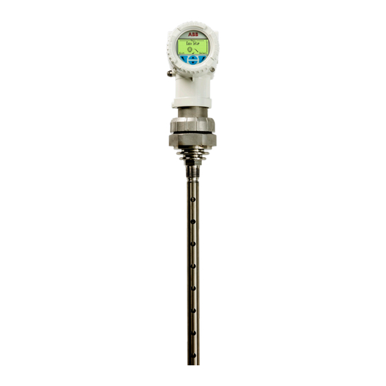
First look Below is a first look at the main components of the LWT series instruments: The head — Figure 2 LWT instrument head Housing cover (terminal side) Nameplate Connection ports (caps removed) Housing cover (display side) External ground connection Ex protection mode identification plate Screwed-on stainless steel plate Housing security screw... -
Page 14: As Shipped
As shipped — Figure 4 Head-coupler assembly User Guide... -
Page 15: Basic Installation Procedure
Repairs, alterations, and enhancements, or the installation of replacement parts, are only permissible as far as these are described in this guide. Approval by ABB must be requested in writing for any activities beyond this scope. Repairs performed by ABB-authorized centers are excluded from this article. -
Page 16: Operator Liability
ABB will gladly support you in selecting the materials, but cannot accept any liability in doing so. Operators must strictly observe the locally applicable national regulations with regard to installation, function tests, repairs, and maintenance of electrical devices. -
Page 17: Installing The Lwt
— C h a p t E R 3 Installing the LWT The following pages explain how to proceed with a typical physical installation of your LWT instrument. Keep in mind that there are numerous possible installation scenarios; this documentation cannot cover them all. -
Page 18: Environmental Considerations
NOTICE If the site where the LWT will be installed is subject to severe vibration conditions, harsh environment errors might be flagged. Contact ABB for information on using a remote coaxial probe installed on a bracket to dampen oscillations. Hazardous area considerations •... -
Page 19: Nozzle-Specific Considerations
• You must use ½-inch NPT/M20 cable glands certified to either Ex db or Ex tb (depending on the installation), and rated to at least IP68/NEMA Type 6P. Cable glands supplied by ABB are ATEX- and CE-certified, and meet the above requirements. -
Page 20: Accessing The Location
Accessing the location DANGER The installation area must be secured. If necessary, tape off all limits of approach to the installation area and ensure that all personnel understands the risks associated with the installation procedure. WARNING Only qualified and authorized personnel should be put in charge of the installation, electrical connection, commissioning, operation, and maintenance of the instrument. -
Page 21: Attaching A Probe To The Coupler/Head Assembly
Attaching a probe to the coupler/head assembly Depending on your specific application, you might have to install a flexible or rigid probe. NOTICE LWT instruments come in a wide variety of configurations. They can come with probes already attached and/or external flanges already soldered or neither. The following pages explain the procedures to perform although those procedures might have already been performed at the factory. - Page 22 — Figure 6 Screwing in the probe 4 Once all the parts are in place, use two wrenches (one holding the head bolt and the other, the probe slot) to apply the recommended torque (see below) in both directions at the same time. —...
-
Page 23: Installing The Lwt System
Installing the LWT system NOTICE Installing the LWT system directly on the top of the vessel provides the best return signal. Once the probe and coupler/head assembly have been attached, you need to: 1 Insert the probe end into the flange, down the nozzle and to the bottom of the vessel. 2 Secure the coupler as necessary: –... -
Page 24: Rotating The Lcd
Rotating the LCD ELECTROSTATIC DISCHARGES Electronic components are sensitive to electrostatic discharges. Before performing any connection, operators shall make sure that they have discharged all static electricity from their body before touching electronic components. When the head unit is installed, it is possible to rotate its LCD in one of four different positions at 90° intervals. - Page 25 — Figure 10 Four positions for the instrument LCD 0° (default) +90° +180° +270° 5 Push back the display module on the communication board, making sure that the four plastic locks are properly fixed. NOTICE Be careful not to bend the connection pins (see Figure 11) when pushing the display back in.
-
Page 26: Grounding The Instrument
Grounding the instrument NOTICE Star or daisy chain configurations are not allowed under any circumstances. The LWT must be grounded in accordance with national electrical codes, using a protective earth (PE) terminal by means of a short connection to an equipotential bonding. The equipotential bonding conductor must have a maximum cross-section of 4 mm²... -
Page 27: Bringing Power To The Instrument
WARNING The terminal block needs to be replaced if the installation shows any sign of damage resulting from direct or indirect lightning discharges. Call ABB in such situations. Bringing power to the instrument ELECTROSTATIC DISCHARGES Electronic components are sensitive to electrostatic discharges. - Page 28 WARNING Do not handle the instrument by the threaded interface. Threaded edges are sharp and could cause personal injuries. NOTICE After an interval of several weeks, increased force will be required to remove the housing cover. This situation is normal; it is caused by the type of gasket used. 4 Route the power cable through the cable gland and the open electrical connection port.
- Page 29 WARNING Securing housing cover in flameproof/explosion proof areas Both sides of the electronics housing feature a M4 hex head locking screw on the bottom side. M4 hex head locking screws To secure a housing installed in a hazardous location: 1 Tighten the housing covers by hand. 2 Turn both locking screws counterclockwise until their head stops at the housing cover.
-
Page 30: Establishing Communication With The Instrument
It allows remote configuration of LWT instruments over legacy 4 – 20 mA analog device current loops, sharing the pair of wires used by analog-only host systems. ABB provides a HART communication package. Once installed in your preferred HART application, it will allow communication with your LWT instruments. -
Page 31: Upon Startup
Upon startup Upon startup, the LCD turns on, the instrument establishes connection and the display starts showing values on Operator page 1 based on the factory-set configuration. NOTICE After power-on, wait for the LCD calibration process to complete (±30 seconds) before operating the TTG display. - Page 32 Page intentionally left blank...
-
Page 33: Introducing The User Interface
— C h a p t E R 4 Introducing the user interface Chapter 5 and Chapter 6 discuss various configuration options, but first you need a basic understanding of the various ways to interact with the instrument. Introducing LWT user interfaces To configure your LWT instrument, you need to understand the access methods to the parameters that you need to change and what to expect when you reach these parameters. -
Page 34: Accessing Menus
By entering the proper password, you will gain access to features and functions associated with this access level. The Service menu can only be accessed by or under the supervision of, ABB service personnel. The icon adjacent to the provided access level is displayed in the system status area. -
Page 35: Navigating The Instrument Display
Navigating the instrument display There are two operations that you can do when navigating the user interface. You can select an existing option, or edit a value. Selecting an option Options can be selected but not modified. This is the easiest operation to perform: 1 Using the arrow and action keys, move up, down, left or right within a menu. - Page 36 Page intentionally left blank...
-
Page 37: Configuring The Instrument At Startup
— C h a p t E R 5 Configuring the instrument at startup Once the LWT instrument is physically installed and properly powered, you might need to configure the various parameters to better suit your needs if they go beyond the default configuration. The following pages explain the first-time Easy Setup configuration (in more details than the Quick Start guide). - Page 38 To configure with the Easy Setup menu: 1 Press Select. The Language menu appears immediately. a Press Edit. The list of available languages appears (default value: English). b Scroll up or down the list and highlight the desired language. c Press OK . The interface changes to the selected language immediately. For more information, see “Language”...
- Page 39 7 Press Next. The Max Level Rate screen appears. This sets the expected rate at which the vessel fills up or is drained. a Press Edit. The list of available values appears (default value: No Filter) b Scroll up or down the list and highlight the required value. c Press OK.
- Page 40 Page intentionally left blank...
-
Page 41: Configuring The Instrument
— C h a p t E R 6 Configuring the instrument Once the LWT instrument is physically installed and properly powered, you might need to configure the various parameters to better suit your needs if they go beyond the default configuration. The following pages explain how to configure these various parameters. -
Page 42: Number Of Decimals
Number of decimals The LWT allows you to set the number of decimals to display on screen for length, flow and volume units. To set the number of decimals to display for these units throughout the interface: 1 Select Display > Length Format, Flow Format or Volume Format. 2 Press Edit. -
Page 43: Configuring Operator Pages
Configuring Operator pages Operator pages display relevant information about ongoing process measurements. The LWT allows you to configure and display up to four different Operator pages. Each Operator page can display bargraphs and/or up to three lines of data. You can scroll automatically between the four Operator pages with the autoscroll feature (see “Enabling Operator page autoscroll”... -
Page 44: Enabling Operator Page Autoscroll
Enabling Operator page autoscroll The autoscroll feature allows you to move automatically between Operator pages at a set time interval. This is useful when you simply want to record specific values manually without touching the instrument. This feature is disabled by default. To enable autoscroll: 1 Select Display >... -
Page 45: Setting Up Role-Based Passwords
Setting up role-based passwords In LWT instruments, these passwords, comprised of six alphanumerical characters, give access to instrument functions and features based on the password entered. To define passwords: 1 Select Device Setup > Access Control > Standard Password or Advanced Password. 2 Press Edit. - Page 46 NOTICE DO NOT use a magnetic screwdriver. — Figure 27 Accessing the write-protection screw Nameplate Write-protection screw 2 Using a suitable screwdriver, fully press down on the write-protection screw and turn 90° clockwise to activate hardware write protection or, if already activated, 90° counterclockwise to deactivate it. —...
-
Page 47: Setting Up The Primary Value (Pv)
Setting up the primary value (PV) The primary value is the value that you want to measure with your LWT instrument. It is configured from the PV Setup menu under the Device Setup menu. — Figure 29 The Device Setup menu Selecting the value The primary value is the only value directly linked to the 4 –... -
Page 48: Configuring The Sensor
NOTICE Unlinking the primary value from the 4 – 20 mA values requires that you manually set 4 mA and 20 mA values afterwards. Menu items for these two values appears in the PV Setup menu to do just that. Values are automatically relinked if either the 4 mA or 20 mA value is modified at a later time. -
Page 49: Setting Up The Application
To disable false echo tracking: 1 Select Device Setup > Sensor Setup > False Echo Tracking. 2 Press Edit. 3 Highlight Disable and press OK. Resetting false echo tracking There are situations, such as modifications made to the vessel, where false echo tracking might need to be reset, effectively erasing the false echo history and starting anew. -
Page 50: Selecting A Tank Type
Selecting a tank type You can set the type of vessel in which the probe will be immersed. The type of vessel impacts the quality and nature of the signal sent down the probe. The default tank type is Metallic. To do so: 1 Select Device Setup >... -
Page 51: Setting Process Conditions
Setting process conditions You can also set the various conditions occurring inside the tank if you want them to be taken into consideration when the instrument is taking measurements. For this to happen, you need to enable any of the following conditions, when relevant: •... -
Page 52: Setting Up A Median Filter
Setting up a median filter The median filter is designed to filter out noisy measurement spikes in applications with fast transients (e.g., rapidly varying processes, positioning applications, etc). It is used for discarding occasional false measurements resulting from any occasional unwanted phenomena that might occur in the process. The value entered corresponds to the number of measurements kept in the buffer. -
Page 53: Setting Process Parameters
Setting process parameters Certain parameters linked to the process itself need to be configured, chiefly process alarms and process safety parameters. The following pages explain how to set these parameters. Setting process alarms Alarms can be raised when process levels reach certain thresholds. Low and high alarm thresholds are factory set and cannot be modified. -
Page 54: Setting Process Safety Parameters
Setting failure mode You can specify whether high or low failures (saturations and alarms) raise an alarm. The default value is Low. To specify the failure mode: 1 Select Process Alarm > Failure Mode. 2 Press Edit. 3 Highlight High or Low and press OK. Setting saturation limits Although process alarm levels cannot be modified, you can modify saturation limits. -
Page 55: Managing Lost Echoes
— Figure 35 Blocking and safety distances Sensor reference point Nozzle length Blocking distance Safety distance Setting a safety distance The safety distance is a distance where you can take measurements, at levels preceding the blocking distance. Essentially, this is the distance between the sensor reference point and the 100 % full/span value, in case you might want to be informed when such levels are reached. -
Page 56: Setting Up Linearization
Reaction You can configure the instrument reaction when echoes are lost for the set period of time: hold the last value measured, hold a constant value, raise an alarm or ramp up results from the last measured value. To do so: 1 Select Device Setup >... - Page 57 — Figure 36 Actual level vs. linearization table points point 3 50 m point 2 15 m point 1 10 m point 0 If Figure 36 was translated in actual values, it could be put in a table as such: —...
-
Page 58: Accessing The Linearization Function
Accessing the linearization function To access the linearization function: 1 Select Device Setup > Linearization > Setup > Output Type. 2 Press Edit. 3 Highlight the measurement value that you want to use (Volume or Flow) and press OK. This activates a series of parameters that will be explained and configured below. Setting the linearization input unit To set the input unit used by the linearization function: 1 Select Device Setup >... -
Page 59: Setting Up Linearization Points
Setting the vessel diameter To set the vessel diameter: 1 Select Device Setup > Linearization > Volume Calculation > Cylinder Diameter. 2 Press Edit. 3 Set the vessel diameter and press OK. Setting the vessel length To set the vessel length: 1 Select Device Setup >... -
Page 60: Managing Saved Linearization Tables
Managing saved linearization tables You can clear an existing linearization table if you want to start from scratch (e.g., if you moved your instrument to a different tank) and you can restore the existing table if you want to erase the linearization table under development and reload the saved table. -
Page 61: Managing Device Setups
Managing device setups Configuring or reconfiguring your instrument could take a non trivial amount of time. With that in mind, once you have properly configured your instrument, you can save your setup as a baseline configuration that you can revert to if necessary. The following pages explain how to proceed. Saving a default user setup To save your current configuration as your default user setup: 1 Select Device Setup >... - Page 62 Page intentionally left blank...
-
Page 63: Setting Calibration Parameters
— C h a p t E R 7 Setting calibration parameters Should configuration with the Easy Setup menu not be enough to meet your needs, you will have to calibrate your instrument and enter specific values to perform this calibration. The following pages explain how to do this. -
Page 64: Changing The Full/Span Value
— Figure 39 Calibration parameters Sensor reference + sensor offset 20 mA (URV) Full/Span 100% Distance Ullage Level 4 mA (LRV) Empty/Zero Level offset Probe length Changing the full/span value This value (probably set initially from the Easy Setup menu) represents the highest level measurement value in your vessel. -
Page 65: Adding A Sensor Offset
Adding a sensor offset A sensor offset is a small distance that you might need to add to the sensor reference value (e.g., if the probe in bent slightly at the junction with the sensor). The default value for this parameter is 0 m. The value can be set between –30 to 30 m. To set that value: 1 Select Calibrate >... -
Page 66: Setting 4 - 20 Ma D/A Trim
Setting 4 – 20 mA D/A trim LWT instruments are factory-calibrated to reflect the published declared performance specifications. No further calibration is required in normal usage condition. Once an LWT is installed and wired, the field wiring and other current loop components may affect the mA output that is received at the point of control. -
Page 67: Resetting The D/A Trim
Resetting the D/A trim To reset the 4 – 20 mA trim: 1 Select Calibrate > 4-20 mA D/A Trim > Reset D/A Trim. 2 Press OK. The D/A trim is reset. Setting a current simulation To validate that calibration was successful, you can simulate a current output. To perform the simulation: 1 Select Calibrate >... - Page 68 Page intentionally left blank...
-
Page 69: Configuring Communications
— C h a p t E R 8 Configuring communications Certain communication parameters are set from the Communication menu, including setting of the instrument network address and activation of the multi-instrument feature (a.k.a. multidrop). — Figure 41 The Communication menu Setting dynamic values The LWT instrument can monitor up to four values. -
Page 70: Activating Multidrop Mode
Activating multidrop mode In multidrop mode, the analog loop current is fixed at 4 mA and it is possible to have more than one instrument on a signal loop. Each instrument must have a unique address. To make your instrument available on a network, you need to activate the multidrop mode. 1 Select Communication >... -
Page 71: Maintenance And Troubleshooting
Additionally, no user/operator adjustments inside LWT instruments are necessary or recommended by ABB. Service tasks that are not explained in this documentation are to be performed at the factory by qualified service personnel only. -
Page 72: Browsing The Diagnostics History
The following table gives you a quick way to identify the basic problems. — Table 2 Basic problem identification from LCD Icon Description Error text Error/Failure Functional check Configuration (e.g., during simulation) Electronic Operation process Out of specification transmitter Maintenance required To obtain more information about the currently diagnosed error, you need to access the Diagnostics operator menu. -
Page 73: Event Codes And Recommendations
F202.019 Surface inside blocking distance Check process conditions and device configuration. F237.020 Sensor Board communication error. Restart the device. If condition persists, call aBB for replacement. F223.023 Electronics NV Failure the electronics must be replaced; call aBB. S082.024 Weak echo amplitude Check installation and process conditions. -
Page 74: Masking Classes Of Events
4–20 ma D/a trim should be performed; if error persists, the communication board must be replaced. F221.040 Electronics Board ROM failure Restart the device. If condition persists, call aBB for replacement. F220.041 Electronics Board RaM failure Restart the device. If condition persists, call aBB for replacement. -
Page 75: Diagnosing From A Waveform
Diagnosing from a waveform Most echo-related problems, as listed in Table 3, can also be diagnosed with the help of the integrated waveform display. Waveform management is performed from the Diagnostics menu. — Figure 44 Accessing the waveform display Introducing the waveform display The waveform display illustrates the signal traveling along the probe. -
Page 76: Navigating Through Echoes
Navigating through echoes Once you have accessed the waveform display, you can browse through and select various echoes, and see their respective distances. Obtaining the distance for the current level The current distance displays the measured distance between the reference point and the level. This feature allows you to select another echo as the level echo (previous or next) and confirm that the measured distance matches the real distance. -
Page 77: Performing Simulations And Tests
Performing simulations and tests The simulation tools, found in the Simulation menu under the Diagnostics menu, help confirm proper communication of measured values. There are three standard simulations all performed in a similar way (distance, level, ullage). There are also current simulations. All are explained below. —... -
Page 78: Obtaining Device Status Data
Obtaining device status data For diagnostic purposes, you may need to gather data about the status of the instrument (probe length, current voltage [as well as minimum and maximum recorded], current electronics temperature [as well as minimum and maximum recorded] and total instrument run time). Probe length To confirm probe length: 1 Select Diagnostics >... -
Page 79: Total Run Time
The total run time of the instrument is indicated. 2 Press Back to return to the Device Status menu. Accessing device information When calling an ABB service representative, you might be asked to provide any of the following information, available from the Device Info menu: —... - Page 80 Page intentionally left blank...
-
Page 81: A Specifications
— a p p E N D I x a Specifications For instrument specifications, refer to the instrument datasheet. - Page 82 Page intentionally left blank...
- Page 83 — a p p E N D I x B HMI menu tree The following pages provide an overview of the various menu items accessible through the instrument human-machine interface (HMI). First-level menu Menu item Details Main chapters access Level page B79 Easy Setup page B80...
- Page 84 Easy Setup menu Item Language Set pV (4-20ma) pV Unit ↓Empty/Zero ↑Full/Span application Category Max Level Rate Display Line1 View1 Device Setup menu Item Submenus access Control Standard password advanced password Reset password Write protect Software Wp hardware Wp pV Setup Set pV (4-20ma) pV Unit Link 4-20ma to Z/S...
- Page 85 Item Submenus application Setup probe type probe Length tank type Nozzle Length Bypass/SW pipe Diam. End Of probe Mode Remote transmitter process Conditions Buildup Foam Flashing Emulsion agitated Changing DC Filtering Damping Median Filter Max Level Rate Safety Settings Blocking Distance Safety Distance Safety Dist.
- Page 86 Display menu Item Submenus Language Contrast Operator pages Operator page 1 Operator page 2 Operator page 3 Operator page 4 autoscroll Length format Flow format Volume Format Date/time Format Process Alarm menu Item Submenus alarm source Failure Mode Low alarm current high alarm current alarm Delay Saturation Limits...
- Page 87 Diagnostics menu Item Submenus Waveform at Sensor Ref point at Level at Distance at End of probe Record Waveform Level Echo Selection Current Distance Select previous Echo Select Next Echo Confirm Current Echo Diagnostic history Clear history Class Masking Maintenance Req. Check Function Off Specification Info/None...
- Page 88 Device Info menu Item Manufacturer Name Model Device ID Device Serial Number Order Code Manufacturing Date Installation Date Last Modification Date address City phone Number Software revision hardware revision Communication menu Item Submenus Dynamic Variables Multi-drop mode Devices address Message Last Command Device ID Manufacturer ID...
- Page 92 We reserve the right to make technical changes or modify the contents of this document without prior notice. With regard to purchase orders, the agreed particulars shall prevail. ABB does not accept any responsibility whatsoever for potential errors or possible lack of information in this document.
Need help?
Do you have a question about the LWT300 series and is the answer not in the manual?
Questions and answers