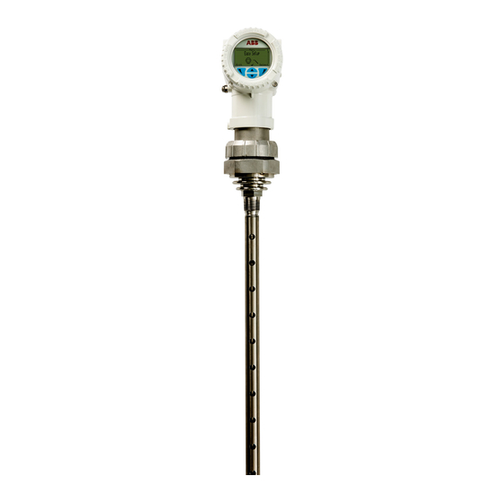
ABB LWT300 Series Quick Start Manual
Hide thumbs
Also See for LWT300 Series:
- User manual (108 pages) ,
- Quick start manual (8 pages) ,
- User manual (92 pages)
Advertisement
Quick Links
—
LWT300 series (Modbus)
Quick Start Guide
Unpacking
If you are reading this document, you have already opened the box containing your instrument. While
following the basic safety instructions provided below, proceed with unpacking the content of this box.
Basic safety
Personnel
WARNING
Only properly certified and authorized personnel should be charged with instrument
installation, electrical connection, commissioning, operation and maintenance.
Depressurize the vessel before opening the instrument connection. Any process media
released may cause severe injuries.
Carefully plan any installation, modification or repair before actually proceeding.
Electrical
WARNING
Do not make electrical connections unless the electrical code designation stamped on the
instrument data plate matches the classification of the area in which you want to install the
instrument. Failure to comply with this warning can result in fire or explosion.
Use only tools compliant with national insulation standards, e.g., DIN EN 60900.
Use only non-sparking tools when installing the instrument in hazardous areas.
Improper use
It is prohibited to use the instrument for any of the following, including but not limited to:
• A climbing aid, e.g., for mounting purposes.
• A support for external loads, e.g., as a support for pipes.
• By adding material, e.g., by painting over the name plate, or welding/soldering on parts.
• By removing material, e.g., by drilling the housing.
Advertisement

Summary of Contents for ABB LWT300 Series
- Page 1 — LWT300 series (Modbus) Quick Start Guide Unpacking If you are reading this document, you have already opened the box containing your instrument. While following the basic safety instructions provided below, proceed with unpacking the content of this box. Basic safety...
- Page 2 • Quick Start Guide (this document) • USB key (with user guide, safety guide, datasheet, customer data package [optional]) Should any part of the package be damaged upon reception, contact ABB customer service as indicated on the back cover of your user guide.
- Page 3 Basic physical installation Below is a list of basic steps necessary to properly install LWT series instruments, as recommended by ABB. All installations should be performed by certified and authorized personnel in accordance with all applicable local security codes (electrical, engineering, etc.).
-
Page 4: Initial Software Setup
Initial software setup Initial setup of the instrument is performed via the menu. Below you will find menu Easy Setup items, factory-set values (in bold) and lists of all available values when you click from the Select Easy screen (if you need to configure your instrument for an oil & gas application, see "Configuring Setup instrument for oil &... - Page 5 Ullage displayed, under the measured value) PV Percent External Temperature Empty Distance Span Probe Length Media Level All menus available in your LWT instrument are explained in more detail in the accompanying user’s guide. LWT300 series (Modbus) Quick Start Guide...
- Page 6 Oil & gas application-specific considerations The oil & gas market is the main user of Modbus guided-wave radar level transmitters. As such, specific considerations are in order. Mounting • Avoid mounting the instrument's probe too close to the vessel inlet or to internal objects (15 cm [6 in]). •...
- Page 7 • To improve performance and minimize the size of the dead zone, we recommend using the puck- shaped weight (height: 2.5 cm [1 in], diameter: 7.3 cm [2 7/8 in]) (ABB order code QP6). • Use "long" weights ONLY if the diameter of the vessel top opening does not allow you to use of the puck-shaped version.
- Page 8 • Dynamic variables (in the Device Setup > Dynamic Variable > Set PV, Set SV, Set TV, Set QV menu). The LWT instrument can monitor up to four variables. These variables are identified as primary (PV), secondary (SV), tertiary (TV), and quaternary (QV). If you initially configured your LWT instrument with the help of the Easy Setup menu, you have already defined the primary variable (PV).
- Page 9 Exit (8 ) or Edit ( ) indicator Zoom information Reference distance Display value selector Level amplitude threshold (or Interface amplitude threshold, if INT is selected in 1) marker Blocking distance (or safety distance, if SFD is selected in 2) marker LWT300 series (Modbus) Quick Start Guide...
- Page 10 ABB, Inc. document without prior notice. With regard to purchase orders, the agreed Measurement & Analytics particulars shall prevail. ABB does not accept any responsibility whatsoever 3400, rue Pierre-Ardouin for potential errors or possible lack of information in this document.


Need help?
Do you have a question about the LWT300 Series and is the answer not in the manual?
Questions and answers