ABB TTH200 Operating Instruction
Head-mount temperature transmitter
Hide thumbs
Also See for TTH200:
- Commissioning instruction (24 pages) ,
- Additional instructions (20 pages) ,
- Operating instruction (24 pages)
Table of Contents
Advertisement
—
A B B M E A S U R E M E N T & A N A L Y T I C S | O P E R A T I N G I N S T R U C T I O N
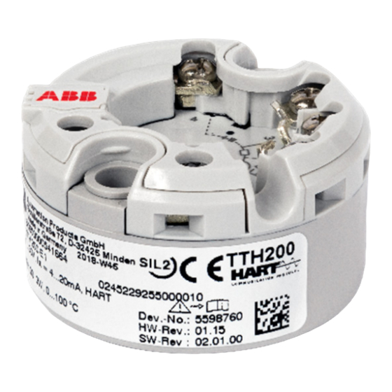
TTH200
Head-mount temperature transmitter
Introduction
—
TTH200
The TTH200 with the 4 to 20 mA output and
HART communications protocol has global
approvals for explosion protection up to Zone 0.
Safety-relevant applications up to SIL 3
(redundant) are supported in accordance with
IEC 61508.
The TTH200 features a universal sensor input for
resistance thermometer, thermocouples,
resistance and voltage measurement.
Temperature transmitter for HART
protocol.
Suitable for all standard
requirements
Measurement made easy
Additional Information
Additional documentation on TTH200 is available for
download free of charge at
www.abb.com/temperature.
Alternatively simply scan this code:
Advertisement
Table of Contents

Related Manuals for ABB TTH200


Summary of Contents for ABB TTH200
- Page 1 Introduction Additional Information — TTH200 The TTH200 with the 4 to 20 mA output and Additional documentation on TTH200 is available for HART communications protocol has global download free of charge at approvals for explosion protection up to Zone 0.
-
Page 2: Table Of Contents
TTH200 HEAD-MOUNT TEMPERATURE TRANSMITTER | OI/TTH200-EN REV. B Table of contents Change from one to two columns Installation ..............14 Safety ................3 Installation options ............... 14 General information and instructions ........3 Installation in the cover of the connection head ..14 ... -
Page 3: General Information And Instructions
TTH200 HEAD-MOUNT TEMPERATURE TRANSMITTER | OI/TTH200-EN REV. B 1 Safety General information and instructions Warnings The warnings in these instructions are structured as follows: These instructions are an important part of the product and must be retained for future reference. -
Page 4: Intended Use
/ or theft of data or information. • When using as a SIL-device in safety-relevant applications, ABB Automation Products GmbH and its affiliates are not liable the SIL Safety Manual should be observed. for damages and / or losses related to such security breaches,... -
Page 5: Use In Potentially Explosive Atmospheres In Accordance With Atex And Iecex
TTH200 HEAD-MOUNT TEMPERATURE TRANSMITTER | OI/TTH200-EN REV. B 2 Use in potentially explosive atmospheres in accordance with ATEX and IECEx Change from one to two columns Note LCD indicator • Further information on the approval of devices for use in... -
Page 6: Temperature Data
TTH200 HEAD-MOUNT TEMPERATURE TRANSMITTER | OI/TTH200-EN REV. B … 2 Use in potentially explosive atmospheres in accordance with ATEX and IECEx Electrical data Temperature data Transmitter Transmitter Intrinsic safety type of protection Ex ia IIC (part 1) ATEX / IECEx intrinsic safety... -
Page 7: Lcd Indicator
TTH200 HEAD-MOUNT TEMPERATURE TRANSMITTER | OI/TTH200-EN REV. B LCD indicator Electrical connections Intrinsic safety type of protection Ex ia IIC Grounding If, for functional reasons, the intrinsically safe circuit needs to be grounded by means of a connection to the potential Supply circuit equalization, it may only be grounded at one point. - Page 8 TTH200 HEAD-MOUNT TEMPERATURE TRANSMITTER | OI/TTH200-EN REV. B … 2 Use in potentially explosive atmospheres in accordance with ATEX and IECEx … Installation instructions ATEX - Zone 1 (0) ATEX - Zone 0 Designation: II 1 G Ex ia IIC T6 Ga...
-
Page 9: Commissioning
TTH200 HEAD-MOUNT TEMPERATURE TRANSMITTER | OI/TTH200-EN REV. B ATEX - Zone 1 (20) When using the transmitter in Zone 2, observe the following: Marking: II 2 G (1D) Ex [ia IIIC Da] ib IIC T6 Gb • The temperature transmitter must be installed in its own housing. -
Page 10: Use In Potentially Explosive Atmospheres In Accordance With Fm And Csa
TTH200 HEAD-MOUNT TEMPERATURE TRANSMITTER | OI/TTH200-EN REV. B 3 Use in potentially explosive atmospheres in accordance with FM and CSA Change from one to two columns Note LCD indicator • Further information on the approval of devices for use in... -
Page 11: Electrical Connections
TTH200 HEAD-MOUNT TEMPERATURE TRANSMITTER | OI/TTH200-EN REV. B Installation in a potentially explosive atmosphere Electrical connections Transmitters can be installed in all kinds of industrial sectors. Grounding Potentially explosive systems are divided into zones, If, for functional reasons, the intrinsically safe circuit needs to be... -
Page 12: Design And Function
TTH200 HEAD-MOUNT TEMPERATURE TRANSMITTER | OI/TTH200-EN REV. B 4 Design and function 5 Product identification General Name plate Digital transmitters are communication-ready devices with Note microprocessor-controlled electronics. They conform to the Products that are marked with the adjacent symbol requirements of IP rating IP 20 and are suited for integration may not be disposed of as unsorted municipal waste into DIN A and DIN B sensor heads. -
Page 13: Transport And Storage
TTH200 HEAD-MOUNT TEMPERATURE TRANSMITTER | OI/TTH200-EN REV. B 6 Transport and storage Inspection Devices with an explosion-proof design are marked with the Check the devices immediately after unpacking for possible following special data plate. damage that may have occurred from improper transport. -
Page 14: Installation
TTH200 HEAD-MOUNT TEMPERATURE TRANSMITTER | OI/TTH200-EN REV. B 7 Installation Installation options There are three options for installing the transmitter: Note • Installation in the cover of the connection head Before mounting the transmitter on the measuring inset, remove (without springs) the ceramic block on the measuring inset and the captive screws •... -
Page 15: Installing / Removing The Optional Lcd Indicator
TTH200 HEAD-MOUNT TEMPERATURE TRANSMITTER | OI/TTH200-EN REV. B 8 Electrical connections Installing / removing the optional LCD Safety instructions indicator DANGER The transmitter can be optionally equipped with an LCD indicator. Improper installation and commissioning of the device carries a risk of explosion. -
Page 16: Protection Of The Transmitter From Damage Caused By Highly Energetic Electric Interferences
TTH200 HEAD-MOUNT TEMPERATURE TRANSMITTER | OI/TTH200-EN REV. B … 8 Electrical connections Protection of the transmitter from damage Suited protective measures caused by highly energetic electric The following items should be observed to protect the transmitter from sensor-side damage: interferences •... -
Page 17: Pin Assignment
TTH200 HEAD-MOUNT TEMPERATURE TRANSMITTER | OI/TTH200-EN REV. B Pin assignment A Potentiometer, four-wire circuit G Voltage measurement B Potentiometer, three-wire circuit H Thermocouple C Potentiometer, two-wire circuit I Interface for type AS LCD indicator D RTD, four-wire circuit 1 to 4 Sensor connection (of measuring inset) -
Page 18: Electrical Data For Inputs And Outputs
TTH200 HEAD-MOUNT TEMPERATURE TRANSMITTER | OI/TTH200-EN REV. B … 8 Electrical connections Electrical data for inputs and outputs Input - resistance thermometer / resistances Input - thermocouples / voltages Resistance thermometer Types • Pt100 in accordance with IEC 60751, JIS C1604, MIL-T-24388 B, E, J, K, N, R, S, T in accordance with IEC 60584 •... -
Page 19: Output - Hart
TTH200 HEAD-MOUNT TEMPERATURE TRANSMITTER | OI/TTH200-EN REV. B Power supply Output – HART® Two-wire technology, polarity safe; power supply lines = signal lines Note Note The HART® protocol is an unsecured protocol, as such the Following calculations apply for standard applications. This... -
Page 20: Commissioning
TTH200 HEAD-MOUNT TEMPERATURE TRANSMITTER | OI/TTH200-EN REV. B … 8 Electrical connections 9 Commissioning … Power supply General Voltage drop on the signal line In case of corresponding order the transmitter is ready for When connecting the devices, note the voltage drop on the operation after mounting and installation of the connections. -
Page 21: Parameterization Of The Device
TTH200 HEAD-MOUNT TEMPERATURE TRANSMITTER | OI/TTH200-EN REV. B Parameterization of the device Note The device does not have operating elements for The device is listed with the FieldComm Group. parameterization on site. Parameterization takes place via the HART interface. Parameterization of the device takes place via standard HART®... -
Page 22: Parameter Descriptions
TTH200 HEAD-MOUNT TEMPERATURE TRANSMITTER | OI/TTH200-EN REV. B … 9 Commissioning … Parameterization of the device Parameter descriptions DTM menu path, parameters Description <Device> / <Extras> <Write Protection> Activates write protection for the entire device • Yes: locked, entry combination: ≠ 0110 •... - Page 23 TTH200 HEAD-MOUNT TEMPERATURE TRANSMITTER | OI/TTH200-EN REV. B DTM menu path, parameters Description <Device> / <Configuration> <Sensor / Reference junction> • Internal: use of the internal reference junction of the transmitter when using a thermocouple / compensating cable (relevant for all thermocouples except for type B) •...
-
Page 24: Factory Settings
TTH200 HEAD-MOUNT TEMPERATURE TRANSMITTER | OI/TTH200-EN REV. B … 9 Commissioning … Parameterization of the device Factory settings The transmitter is configured at the factory. The table below contains the relevant parameter values. Menu Designation Parameter Factory setting Device Setup... -
Page 25: Basic Setup
TTH200 HEAD-MOUNT TEMPERATURE TRANSMITTER | OI/TTH200-EN REV. B Basic Setup Sensor error adjustment (DTM adjustment function) D / A analog output adjustment (4 mA- and 20 mA-Trim) Sensor error adjustment can be performed in the DTM by D/A analog output adjustment is used to compensate for errors navigating to the menu path Device / Calibration. -
Page 26: Hart Variables
TTH200 HEAD-MOUNT TEMPERATURE TRANSMITTER | OI/TTH200-EN REV. B … 9 Commissioning 10 Operation … Basic Setup Safety instructions HART variables If there is a chance that safe operation is no longer possible, The transmitter provides three HART variables. The HART... -
Page 27: Error Messages On The Lcd Display
TTH200 HEAD-MOUNT TEMPERATURE TRANSMITTER | OI/TTH200-EN REV. B 11 Diagnosis / error messages The transmitter signals messages and errors in different ways. Error messages on the LCD display Messages via the HART interface If the event of an error, a message consisting of a symbol or The transmitter signals changed configuration or parameter letter (device status) and a number (DIAG NO.) will appear at the... -
Page 28: Possible Error Messages - Hart
Check parameters: • Sensor limits up-scaled • Measuring span is too small Note If the remedial measures listed for the error message do not improve the status of the device, please consult ABB Service. Change from one to two columns... -
Page 29: Maintenance
9. disposal or must observe the following regulations for shipping purposes: All devices delivered to ABB must be free from any hazardous materials (acids, alkalis, solvents, etc.). Please contact Customer Center Service acc. to page 4 for... -
Page 30: Recycling And Disposal
15 Specification Note Note Products that are marked with the adjacent symbol The device data sheet is available in the ABB download area at may not be disposed of as unsorted municipal waste www.abb.com/temperature. (domestic waste). They should be disposed of through separate collection of electric and electronic devices. -
Page 31: Appendix
TTH200 HEAD-MOUNT TEMPERATURE TRANSMITTER | OI/TTH200-EN REV. B 17 Appendix Return form Statement on the contamination of devices and components Repair and/or maintenance work will only be performed on devices and components if a statement form has been completed and submitted. - Page 32 We reserve the right to make technical changes or modify the contents of this document without prior notice. With regard to purchase orders, the agreed particulars shall prevail. ABB does not accept any responsibility whatsoever for potential errors or possible lack of information in this document.
Need help?
Do you have a question about the TTH200 and is the answer not in the manual?
Questions and answers