Sign In
Upload
Download
Table of Contents
Contents
Add to my manuals
Delete from my manuals
Share
URL of this page:
HTML Link:
Bookmark this page
Add
Manual will be automatically added to "My Manuals"
Print this page
×
Bookmark added
×
Added to my manuals
Manuals
Brands
Lindy Manuals
Extender
38266
User manual
Lindy 38266 User Manual
4k hdmi & usb over ip extender
Hide thumbs
1
2
Table Of Contents
3
4
5
6
7
8
9
10
11
12
13
14
15
16
17
18
19
20
21
22
23
24
25
26
27
28
29
30
31
32
page
of
32
Go
/
32
Contents
Table of Contents
Bookmarks
Table of Contents
Table of Contents
Introduction
Package Contents
Features
Specifications
Overview
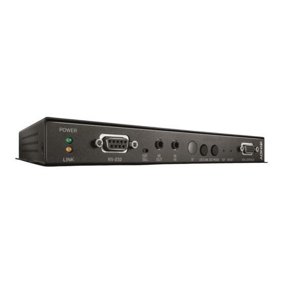
No. 38266 - TRANSMITTER UNIT
No. 38267 - RECEIVER UNIT
Ir Receivers and Emitters
Installation
Operation
Webgui CONTROL
TRANSMITTER UNIT (No.38266) - Detailed Webgui Description
RECEIVER UNIT (No.38267) - Detailed Webgui Description
Telnet Control
Rs232 Interfaces Description
Advertisement
Quick Links
Download this manual
4K HDMI & USB Over IP Extender
User Manual
Eng lis h
No. 38266 - Transmitter
No. 38267 - Receiver
lindy.com
Tested to comply with
FCC Standards
For Home and Office Use!
© LINDY Group - FIRST EDITION
(January 2019)
Table of
Contents
Previous
Page
Next
Page
1
2
3
4
5
Advertisement
Table of Contents
Need help?
Do you have a question about the 38266 and is the answer not in the manual?
Ask a question
Questions and answers
Related Manuals for Lindy 38266
Extender Lindy 38216 User Manual
C6 hdmi 4x4 matrix premium, 100m with hdbaset technology (12 pages)
Extender Lindy 38200 User Manual
(24 pages)
Extender Lindy 38209 User Manual
C6 hdmi 2.0 & usb kvm extender 100m (24 pages)
Extender Lindy 38267 User Manual
4k hdmi & usb over ip extender (32 pages)
Extender Lindy 38281 Quick Manual
Presentation switch pro with hdbaset extender (20 pages)
Extender Lindy 38219 User Manual
100m c6 hdmi 2.0 18g hdbaset extender (20 pages)
Extender Lindy 38205 User Manual
50m cat.6 hdmi 18g & ir extender with poc & loop out (24 pages)
Extender Lindy 38264 User Manual
Kvm over ip extender, transmitter/receiver (24 pages)
Extender Lindy 38204 User Manual
200m fibre optic hdmi 18g extender (8 pages)
Extender Lindy 382257 User Manual
Hdmi over powerline extender (16 pages)
Extender Lindy 38208 User Manual
70m cat.6 hdmi 10.2g & ir extender with poc & loop out (20 pages)
Extender Lindy 38262 User Manual
(24 pages)
Extender Lindy 38003 User Manual
(17 pages)
Extender Lindy HDMI over Ethernet Extender User Manual
Hdmi over ethernet extender (6 pages)
Extender Lindy 38139 User Manual
C6 hdmi extender, 70m (12 pages)
Extender Lindy 38169 User Manual
50m cat.6 hdmi 2.0 & ir extender with poc (12 pages)
This manual is also suitable for:
38267
Table of Contents
Print
Rename the bookmark
Delete bookmark?
Delete from my manuals?
Login
Sign In
OR
Sign in with Facebook
Sign in with Google
Upload manual
Upload from disk
Upload from URL


Need help?
Do you have a question about the 38266 and is the answer not in the manual?
Questions and answers