Prolon NC2000 Hardware Manual
Network controller
Hide thumbs
Also See for NC2000:
- Quick start manual (14 pages) ,
- Technical reference manual (98 pages)

Subscribe to Our Youtube Channel
Related Manuals for Prolon NC2000


Summary of Contents for Prolon NC2000
- Page 1 HARDWARE GUIDE Network Controller - NC2000 Specifications and Operational Guide www.proloncontrols.com | info@proloncontrols.com 17 510, rue Charles, Suite 100, Mirabel, QC, J7J 1X9 REV. 6.1.6 PL-HRDW-NC2000-C/F-EN...
-
Page 2: Table Of Contents
Figure 5 - Communication Reset Button........................8 Figure 6 - Inbound Communication ..........................9 Figure 7 - RJ45 Pinout ..............................11 Figure 8 - Outbound Communication ........................12 Figure 9 - NC2000 Size Diagram ........................... 15 REV. 6.1.6 / PL-HRDW-NC2000-C/F-EN... -
Page 3: General Information
Email-based alerts The NC2000 can also be used as a remote alarming system. It can be configured to poll any data point (temperature readings, output actions, demands, etc…) from any ProLon controller and then send email- based alerts whenever the data points meet or exceed user-selectable conditions. -
Page 4: Trend Logs
Data can be recorded at configurable intervals or upon a user-specified change of value. The NC2000 records the data onto a standard-size SD card (SDSC or SDHC) which can be plugged into the NC2000 and removed at will. Trend logs can also be downloaded directly from the NC2000 without removing the SD card, using the ProLon Focus software. -
Page 5: Components
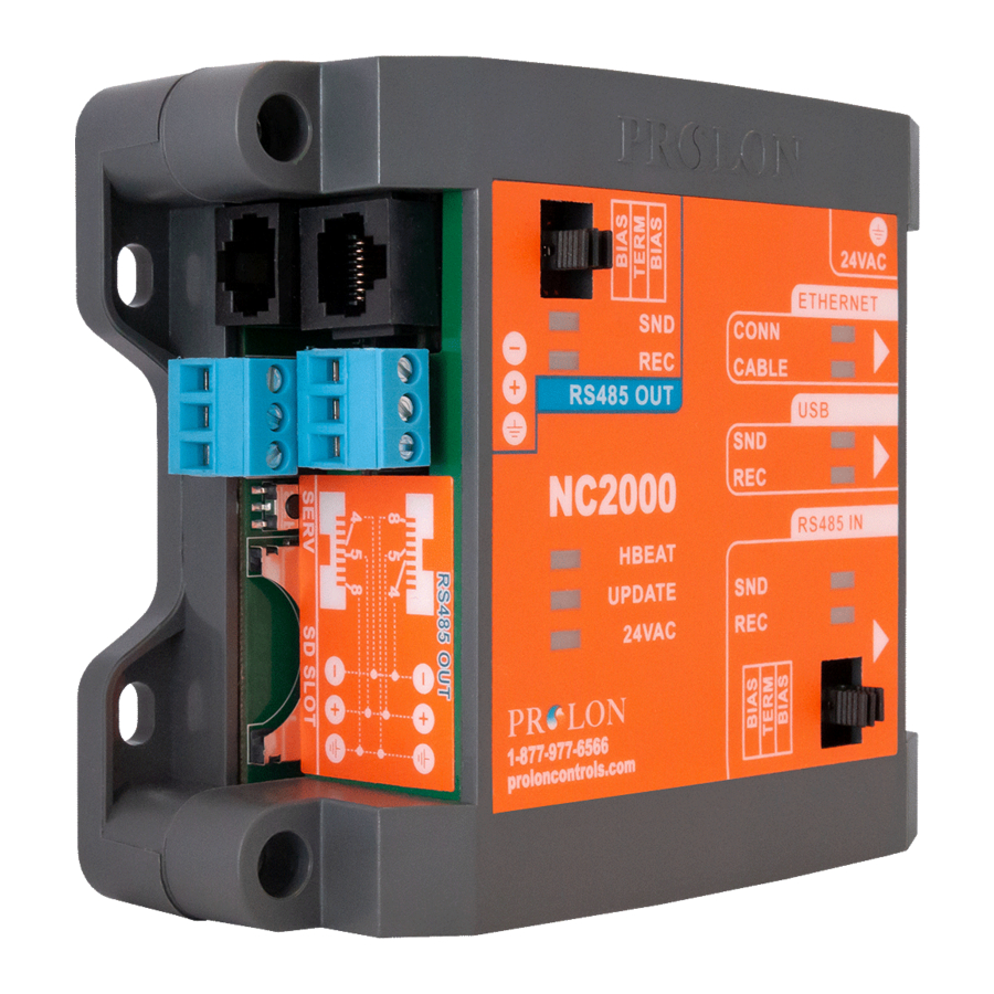
G - RS485 IN Port (3 terminal block and 1 RJ45 jack in parallel) H - Jumpers for terminating and bias resistors for the RS485 OUT port I - Jumpers for terminating and bias resistors for the RS485 IN port REV. 6.1.6 / PL-HRDW-NC2000-C/F-EN... -
Page 6: Leds
LEDs The NC2000 has a variety of LEDs visible on the front cover that are linked to different functions of the controller. Each LED is individually identified to help the user make a quick visual diagnostic of the controller’s activity and status. -
Page 7: Jumpers
Jumpers The NC2000 has jumpers that are externally accessible that allow for configuration of the bias and termi- nating resistors used on both RS485 communication ports. RS485 RS485 IN RS485 Figure 3 - Location of the EXTERNAL jumpers Activating a jumper enables the associated resistor on the respective communication port. To disable a resistor, remove the jumper (setting the jumper on only a single pin is the same as removing it). -
Page 8: Communication Settings Reset Button
Communication Settings Reset Button The NC2000 has a button located on the left side of the controller that can be used to reset the IP address, as well as other important settings related to communication, in case they are forgotten or lost. After... -
Page 9: Communication Ports
ProLon Focus App software, either locally or remotely through the internet. The messages received at the inbound ports are interpreted by the NC2000 and then forwarded outwards to the ProLon RS485 network as required. The default Modbus address of the NC2000 itself, regardless of the port being used, is 99. Ethernet... -
Page 10: Ethernet Port - Tcp/Ip
TCP port 502, such as those generated by ProLon Focus software. Because the NC2000 is in DHCP mode by default, its local IP address may vary. Refer to your router for more information. Alternatively, the NC2000 can be configured with a static IP address. This can be done by using the Communication Settings Reset button (see p.8) to allow initial access, or by using one of the... -
Page 11: Rs485 In Port
The NC2000 also comes equipped with an RS485 IN port that is only used for communication that is directed to the NC2000 from a computer or other interface. The NC2000 acts as a Modbus RTU slave on this port and will not initiate communication on its own. This is not the appropriate port to connect the rest of the ProLon controllers (rooftop controllers, zone controllers, thermostats, etc…). -
Page 12: Outboud Communication
Outboud Communication The NC2000 only has a single outbound communication port, the RS485 OUT port. This port is intended to be wired to the actual network of ProLon controllers communicating in Modbus RTU over RS485 (rooftop controllers, zone controllers, thermostats, etc…). On this port, the NC2000 acts as a network Master, initiating communication to the controllers, polling them and distributing information. -
Page 13: Technical Specifications
Microprocessor: ASIX AX11015, 8 bits, 25 MHz, 512 KB FLASH memory Battery: Super-capacitor 0.5F, keeps precise time for 10 days. This battery is only used to keep accurate time during power outages. Does not allow the NC2000 to keep transmitting data, send alarms or perform data logging. -
Page 14: Compliance
(1) this device may not cause harmful interference, and (2) this device must accept any interference received, including interference that may cause undesired operation. Caution: Any changes or modifications not approved by ProLon can void the user’s authority to operate the equipment. -
Page 15: Overall Dimensions
No part of this document may be photocopied or reproduced by any means, or translated to another language without prior written consent of ProLon. All specifications are nominal and may change as design improvements are introduced. ProLon shall not be liable for damages resulting from misapplication or misuse of its products.
Need help?
Do you have a question about the NC2000 and is the answer not in the manual?
Questions and answers