Prolon M2000 Series Hardware Manual
Rooftop controller
Hide thumbs
Also See for M2000 Series:
- Hardware manual (21 pages) ,
- Quick start manuals (16 pages) ,
- Technical reference manual (98 pages)

Subscribe to Our Youtube Channel
Related Manuals for Prolon M2000 Series


Summary of Contents for Prolon M2000 Series
- Page 1 HARDWARE GUIDE Rooftop Controller M2000 Series Specifications and Operational Guide www.proloncontrols.com | info@proloncontrols.com 17 510, rue Charles, Suite 100, Mirabel, QC, J7J 1X9 REV. 6.1.8 PL-HRDW-RTU-M2000-C/F-EN...
-
Page 2: Table Of Contents
Table of Contents General Information ..........................4 PL-M2000 Rooftop Controller ....................... 4 Description ..................................4 General Behaviour ................................ 4 Operating Sequence ........................5 General .................................... 5 Occupied Mode ................................5 Unoccupied Mode ................................ 5 Components ............................6 Component Identification ............................6 LEDs and Switches ................................ - Page 3 Table of Figures Figure 1 - Component Identification ..........................6 Figure 2 - LEDs Identification ............................7 Figure 3 - Location of the EXTERNAL jumpers ......................8 Figure 4 - Location of the INTERNAL jumpers ......................8 Figure 5 - INT and NET jumpers ............................8 Figure 6 - AI jumpers .................................
-
Page 4: General Information
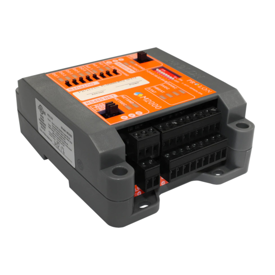
PL-M2000 Rooftop Controller Description The ProLon PL-M2000 RTU Rooftop controller is a microprocessor-based controller designed to operate rooftops or other mechanical HVAC systems. It uses PI (Proportional-Integral) control loops and acts as a master when used on a network with ProLon zone controllers. -
Page 5: Operating Sequence
Operating Sequence General The ProLon M2000 RTU Rooftop controller receives readings from five different temperature sensors: outside air, return air, supply air, mixed air and zone air. In addition to the temperature sensors, it also has inputs for the static pressure, CO2 levels and proof of fan. It operates on a configurable schedule using an internal real time clock. -
Page 6: Components
Components Component Identification Figure 1 - Component Identification Legend: A - Addressing Dipswitch B - AUTO/OFF/HAND Switches C - RS485 INT port for interface communication (RJ45 plug and screw connectors are in parallel) D - Analog outputs (3) E - Digital outputs (5) F - Analog inputs (9) G - RS485 NET port for network communication H - Terminal block for 24VAC (Class 2 transformer) -
Page 7: Leds And Switches
(normal). When this LED is ON and steady, the M2000 is inactive and the microchip is awaiting • AO1: The intensity of the LED represents the programming (you must use ProLon’s Focus voltage present on analog output 1. software to reprogram the microchip). -
Page 8: Hand/Off/Auto Switches
Figure 4 - Location of the INTERNAL jumpers • INT: These are the jumpers for the bias and terminating resistors used for the interface communication bus. See the ProLon network guide for information about bias and terminating resistors. (See Figure 5) •... -
Page 9: Input And Output Identification
Bottom Row: Common for all inputs Static pressure (0-5 / 1-5V) (1 / 1.5 / 2 / 2.5 in) RTUS Incoming communication INT Port: ProLon Digital CO2 sensor (4-20 mA) from remote computer or Temperature Sensor network controller - OR -... -
Page 10: Addressing Dipswitch Configuration For Network Communication
The example in Figure 9 shows the switches 1, 2 and 4 in the ON position. Therefore, the corresponding values are 1, 2 and 8, giving an address sum of 11. The ProLon network allows a maximum of 127 addresses; therefore 127 controllers. Figure 9 - Addressing Dipswitch... -
Page 11: Inputs
Inputs Temperature Sensors The M2000 Rooftop controller has four analog inputs that monitor outside air, supply air, return air and mixed air temperatures (see Figure 10) and will integrate these readings into its control sequence. The sensors used are standard 10k type thermistors that share a single common connection. Alternatively, the supply air temperature can be retrieved from a zone controller that has its own supply sensor and belongs to the M2000’s network. -
Page 12: Room Sensors
Room Sensors The M2000 RTU can receive the setpoint and temperature from a specific room when a PL-RS analog thermostat is connected to it. The M2000 will then automatically integrate this information into its control sequence. The setpoint may also simply be set by software. The PL-RS series room sensors are connected using a 3-conductor cable (see Figure 11). -
Page 13: Dry Contact For Clogged Filter Or Schedule Override
Dry Contact for Clogged Filter or Schedule Override Analog input 4 on the M2000 RTU can also be configured as a dry contact input for either a clogged filter sensor or as a schedule override input. Please refer to Figure 13 to see proper connection. •... -
Page 14: Outputs
The M2000 Rooftop controller contains 8 customizable outputs; five triac ON/OFF outputs (24VAC) and three analog outputs (0-10VDC). Output configuration is performed via the ProLon Focus software. An integrated resettable fuse protects each of the outputs of the M2000 against current surges and short circuits. -
Page 15: Typical Connection Of Triac Outputs 1 To 5
Typical Connection of Triac Outputs 1 to 5 On the M2000 Rooftop controller, all triac outputs produce a 24 VAC live voltage when activated. Note that all output voltages originate from a single voltage supply: the equipment’s transformer. Consequen- tially, only the live side of the output connections are usually needed; these are on the top row (see figure 15). -
Page 16: Dmux-4J Connection On Digital Output 2 For 3 Or 4 Stage Cooling
DMUX-4J Connection on Digital Output 2 for 3 or 4 Stage Cooling When 3 or 4 stages of cooling are required, the M2000 Rooftop controller must be equipped with a DMUX-4J. The DMUX-4J input is only connected to Digital Output 2 on the M2000 Rooftop controller. The DMUX-4J must be configured to “Sequenced Relay Control”... -
Page 17: Pta2 Connection On Digital Output 2 For Analog Cooling
PTA2 Connection on Digital Output 2 for Analog Cooling When proportional modulating cooling is required, the M2000 Rooftop controller must be equipped with a PTA2 v.1. interface to create an analog 0-10Vdc output signal. The PTA2 input is connected to Digital Output 2 on the M2000 Rooftop controller. -
Page 18: Power Source & Network
Figure 19 - Connecting the 24VAC Power Source Network Communication The ProLon M2000 Rooftop controller is designed to work with the ProLon zone controllers. When they are networked, the Rooftop and zone controllers all communicate in real-time. The network connections are made using the network terminal blocks located on the M2000 controller (see Figure 20). -
Page 19: Technical Specifications
Certification: UL916 Energy Management Equipment, CAN/CSA-C22.2, RoHS, FCC part 15: 2012 class B The performance specifications are nominal and conform to acceptable industry standards. ProLon Inc. will not be liable for damages resulting from misapplication or misuse of its products. -
Page 20: Compliance
(1) this device may not cause harmful interference, and (2) this device must accept any interference received, including interference that may cause undesired operation. Caution: Any changes or modifications not approved by ProLon can void the user’s authority to operate the equipment. -
Page 21: Overall Dimensions
No part of this document may be photocopied or reproduced by any means, or translated to another language without prior written consent of ProLon. All specifications are nominal and may change as design improvements are introduced. ProLon shall not be liable for damages resulting from misapplication or misuse of its products.
Need help?
Do you have a question about the M2000 Series and is the answer not in the manual?
Questions and answers