Prolon M2000 Series Hardware Manual
Air make up controller
Hide thumbs
Also See for M2000 Series:
- Hardware manual (21 pages) ,
- Quick start manuals (16 pages) ,
- Technical reference manual (98 pages)
Table of Contents
Advertisement
Quick Links
Download this manual
See also:
Hardware Manual
Advertisement
Table of Contents

Subscribe to Our Youtube Channel
Related Manuals for Prolon M2000 Series


Summary of Contents for Prolon M2000 Series
- Page 1 HARDWARE GUIDE Air Make Up Controller M2000 Series Specifications and Operational Guide www.proloncontrols.com | info@proloncontrols.com 17 510, rue Charles, Suite 100, Mirabel, QC, J7J 1X9 REV. 7.1.0 PL-HRDW-MUA-M2000-C/F-EN...
-
Page 2: Table Of Contents
Table of Contents General Information ..........................4 PL-M2000 Air Make Up Controller ..........................4 Description ..................................4 General Behavior ................................4 Operating Sequence ..............................5 General .................................... 5 Summer Sequence ................................ 5 Winter Sequence ................................5 Mid-Season Sequence ..............................5 Components ............................ - Page 3 Table of Figures Figure 1 - Component Identification ..........................6 Figure 2 - LEDs Identification ............................7 Figure 3 - Location of the EXTERNAL jumpers ......................8 Figure 5 - INT and NET jumpers ............................8 Figure 4 - Location of the INTERNAL jumpers ......................8 Figure 6 - AI jumpers .................................
-
Page 4: General Information
PL-M2000 Air Make Up Controller Description The Prolon PL-M2000 Air Make Up controller is a microprocessor-based controller designed to operate a variety of different make-up air units and systems. It features a variety of control strategies, including outdoor temperature reset, building pressure control, CO2 control, safety limits and more. -
Page 5: Operating Sequence
Operating Sequence General The Prolon M2000 Air Make Up controller follows a strict activation sequence before heating or cooling actions can be taken. The sequence begins with the exhaust fan. When proof of exhaust fan is obtained, the outside air damper is opened. When proof of damper opening is obtained, the fan is activated. Finally, when proof of fan is obtained, heating or cooling action is authorized. -
Page 6: Components
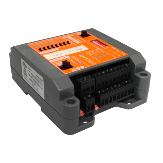
Components Component Identification Figure 1 - Component Identification Legend: A - Addressing Dipswitch B - AUTO/OFF/HAND Switches C - RS485 INT port for interface communication (RJ45 plug and screw connectors are in parallel) D - Analog outputs (3) E - Digital outputs (5) F - Analog inputs (9) G - RS485 NET port for network communication H - Terminal block for 24VAC (Class 2 transformer) -
Page 7: Leds And Switches
(normal). When this LED is ON and steady, the M2000 is inactive and the microchip is awaiting • AO1: The intensity of the LED represents the programming (you must use Prolon’s Focus voltage present on analog output 1. software to reprogram the microchip). -
Page 8: Hand/Off/Auto Switches
Figure 4 - Location of the INTERNAL jumpers • INT: These are the jumpers for the bias and terminating resistors used for the interface communication bus. See the Prolon network guide for information about bias and terminating resistors. (See Figure 5) •... -
Page 9: Input And Output Identification
The M2000 Air Make Up Controller has 2 separate communication ports offering the same functionality on each. Both act as ports for incoming Modbus communications from other Prolon devices or interfaces, such as a Network Controller or remote computer with Prolon Focus software. -
Page 10: Addressing Dipswitch Configuration For Network Communication
The example in Figure 9 shows the switches 1, 2 and 4 in the ON position. Therefore, the corresponding values are 1, 2 and 8, giving an address sum of 11. The Prolon network allows a maximum of 127 addresses; therefore 127 controllers. Figure 9 - Addressing Dipswitch... -
Page 11: Inputs
Inputs Temperature Sensors The M2000 Make Up Air controller has three analog inputs that monitor supply, outside and zone air temperatures (see Figure 10) and will integrate these readings into its control sequence. The sensors used are standard 10k type 3 thermistors that share a single common connection. The outside air temperature can be also be provided by an alternate source. -
Page 12: Building Pressure Or Co2
Building Pressure or CO2 Analog input 9 on the M2000 Make Up Air controller is dedicated to a CO2 or building pressure sensor. By default, a 4-20 mA signal is expected for the CO2 input and a 0-5 or 1-5 VDC signal is expected for the pressure input. -
Page 13: Manual Reset
Manual Reset The M2000 Make Up Air Controller has an input dedicated to the manual reset signal. Please refer to Figure 13 to see how to correctly connect it. Whenever the controller has entered lockout mode, it is required to activate the manual reset switch (close the contact) for 3 seconds to exit lockout mode. Manual Reset Figure 13 - Connecting the Manual Reset Contact to the Controller REV. -
Page 14: Outputs
The M2000 Make Up Air controller contains 8 customizable outputs; five triac ON/OFF outputs (24VAC) and three analog outputs (0-10VDC). Output configuration is performed via the Prolon Focus software. An integrated resettable fuse protects each of the outputs of the M2000 against current surges and short circuits. -
Page 15: Typical Connection Of Triac Outputs 1 To 5
Typical Connection of Triac Outputs 1 to 5 On the M2000 Make Up Air controller, all triac outputs produce a 24 VAC live voltage when activated. Note that all output voltages originate from a single voltage supply: the equipment’s transformer. Consequentially, only the live side of the output connections are usually needed;... -
Page 16: Power Source & Network
Figure 16 - Connecting the 24VAC Power Source Network Communication The Prolon M2000 Make Up Air controller is designed to work standalone or networked with Prolon con- trollers. When networked, it can receive the occupancy status and outside temperature in real-time. The network connections are made using the network terminal blocks located on the M2000 controller (see Figure 17). -
Page 17: Technical Specifications
Environment: 32-122 ºF (0-50 ºC) Non-Condensing Certification: UL916 Energy Management Equipment, CAN/CSA-C22.2, RoHS The performance specifications are nominal and conform to acceptable industry standards. Prolon Inc. will not be liable for damages resulting from misapplication or misuse of its products. -
Page 18: Compliance
(1) this device may not cause harmful interference, and (2) this device must accept any interference received, including interference that may cause undesired operation. Caution: Any changes or modifications not approved by Prolon can void the user’s authority to operate the equipment. -
Page 19: Overall Dimensions
No part of this document may be photocopied or reproduced by any means, or translated to another language without prior written consent of Prolon. All specifications are nominal and may change as design improvements are introduced. Prolon shall not be liable for damages resulting from misapplication or misuse of its products.
Need help?
Do you have a question about the M2000 Series and is the answer not in the manual?
Questions and answers