Table of Contents
Advertisement
Quick Links
Advertisement
Table of Contents

Related Manuals for Shuttle FN41


Summary of Contents for Shuttle FN41
- Page 1 FN41 AMD AthlonXP/Athlon/Duron Processor Based MAIN BOARD...
- Page 2 WARNING Thermal issue is highly essential for processors with a speed of 600MHz and above. Hence, we recommend you to use the CPU fan qualified by AMD or motherboard manufacturer. Meanwhile, please make sure CPU and fan are securely fastened well. Otherwise, improper fan installation not only gets system unstable but also could damage both CPU and motherboard because insufficient thermal dissipation.
- Page 3 The information contained in this manual is provided for general use by the customers. Trademarks Shuttle is a registered trademark of Shuttle Inc. AMD, Athlon, and Duron are registered trademarks of AMD Corporation. Nvidia is a registered trademark of Nvidia Corporation.
-
Page 4: Table Of Contents
2.1 SPECIFICATIONS ..................8 3 HARDWARE INSTALLATION ............11 3.1 STEP BY STEP INSTALLATION ..............11 Accessories of FN41 ................11 STEP 1 Install the CPU ................12 STEP 2 Set Jumpers ................13 STEP 3 Install DDR SDRAM System Memory........13 STEP 4 Install Peripherals in System Case .......... - Page 5 3.2 JUMPER SETTINGS ................. 23 JUMPERS & CONNECTORS GUIDE ............ 24 Jumpers Clear CMOS Setting (JP1) ..............27 Back-Panel Connectors VGA Port Connectors ................28 COM1 Port Connector ................28 TV-Out Connectors ................28 IEEE 1394 Port Connectors ..............28 LAN Port Connector ................
- Page 6 Audio CD-IN Connector (CN6) (Black) ........... 36 IR for Keyboard and Mouse Connectors (JP2)........37 SPDIF Headers (JP7) ................37 IR (JP5) ....................37 AGP Protection LED (D16) ..............38 CPU OVERTEMPERTURE LED (D14) ..........38 3.3 SYSTEM MEMORY CONFIGURATION ............. 39 1.
- Page 7 SET PASSWORD ..................70 SAVE & EXIT SETUP ................71 EXIT WITHOUT SAVING ................71 - 4 -...
-
Page 8: What's In The Manual
WHAT'S IN THE MANUAL Quick Reference Hardware Installation >> Step-by-Step ..........Page 11 Jumper Settings >> A Closer Look ............Page 23 Drivers/Software Utilities >> How to Install .......... Page 40 BIOS Setup >> How to Configure ............Page 45 About This Manual For First-Time DIY System Builder ............ -
Page 9: Introduction
Experienced DIY User Congratulate on your purchase of the Shuttle FN41 mainboard. You will find that installing your new Shuttle FN41 mainboard is just easy. Bundled with an array of onboard functions, the highly-integrated FN41 mainboard provides you with a total solution to build the most stable and reliable system. Refer to sections 3.2 Jumper Settings and Chapter 4 Drivers/Software Utilities to... -
Page 10: Item Checklist
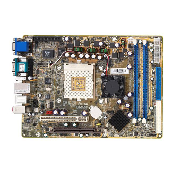
1.2 Item Checklist Check all items with you FN41 mainboard to make sure nothing is missing. The complete package should include: - One piece of Shuttle FN41 Mainboard CD-IN JP12 FAN1 KTS250J2D 1394 FAN1 JP11 JP13 DIMM1 DIMM2 ATXPWR JP10... -
Page 11: Features
2 FEATURES FN41 mainboard is carefully designed for the demanding PC user who wants high perfor- mance and maximum intelligent features in a compact package. 2.1 Specifications - CPU Support Support Socket462 package CPU. AMD AthlonXP/Athlon/Duron Processor with 200/266/333 MHz FSB. - Page 12 - Expansion Slots Provides one 3.0 compliant AGP slot and one 32-bit PCI slots. - 6 USB Interface Onboard Ø 2 USB connectors on back-panel and two sets of dual USB ports headers on mid-board. - I/O Interface Provides a variety of I/O interfaces: Ø...
- Page 13 Provides licensed Award BIOS V6.0 PG on 2Mb Flash core and supports Green PC, Desktop Management Interface (DMI). - ATX Form Factor System board conforms to Shuttle from factor ATX specification. Board dimension: 254mm X185mm. - Advanced Features Ø Low EMI - Built in spread spectrum and automatic clock shut-off of unused PCI/SDRAMS slots to reduce EMI.
-
Page 14: Hardware Installation
Then follow these steps designed to guide you through a quick and correct installation of your system. 3.1 Step-by-Step Installation Accessories Of FN41 COM1 Connector 1394a Ports IEEE1394a RTL8801 TV-Out Connector LAN &... -
Page 15: Step 1 Install The Cpu
Step 1 Install the CPU: 1. Locate the CPU ZIF (Zero Insertion Force) socket on the upper-right sector of your mainboard (between the back-panel connectors and the DIMM memory slots). 2. Pull the CPU ZIF socket lever slightly sideways away from the socket to unlock the lever, and then bring it to an upwardly vertical position. -
Page 16: Step 2 Set Jumpers
Step 2. Set Jumpers This mainboard is jumperless! The default jumper settings have been set for the common usage standard of this mainboard. Therefore, you do not need to reset the jumpers unless you require special adjustments as any of the following cases: Clear CMOS For first-time DIY system builders, we recommend that you do not change the... -
Page 17: Step 4 Install Peripherals In System Case
Step 4 Install Internal Peripherals in System Case Before you install and connect the mainboard into your system case, we recommend that you first assemble all the internal peripheral devices into the computer housing, including but not limited to the hard disk drive (IDE/ HDD), floppy disk drive (FDD), CD-ROM drive, and ATX power supply unit. -
Page 18: Step 5 Mount The Mainboard On The Computer Chassis
Step 5 Mount the Mainboard on the Computer Chassis 1. You may find that there are a lot of different mounting hole positions both on your computer chassis and on the mainboard. To choose correct mounting holes, the key point is to keep the back-panel of the mainboard in a close fit with your system case, as shown below. -
Page 19: Step 6 Connect Front Panel Switches/Leds/Speaker/Usb
Step 6 Connect Front Panel Switches/LEDs/Speaker/USB You can find there are several different cables already existing in the system case and originating from the computer's Front-panel devices (HDD LED, Power LED, Reset Switch, or USB devices etc.) These cables serve to connect the front-panel switches, LEDs, and USB connectors to the mainboard's front- panel connectors group (JP3,JP11, and JP8), as shown below. -
Page 20: Step 7 Connect Ide And Floppy Disk Drives
Step 7 Connect IDE and Floppy Disk Drives 1. IDE cable connector 2. Floppy cable connector Step 8 Connect Other Internal Peripherals 1. CD-IN connector (CN6) CD-IN - 17 -... - Page 21 2. IR header (JP5) 3. IR for K/B Mouse (JP2) IR for K/B Mouse 4. Front Audio (JP6) Front Audio 5. 1394a Controller (JP8) 1394a Header - 18 -...
-
Page 22: Step 9 Connect The Power Supply
7. SPDIF Header (JP7) SPDIF Header Step 9 Connect the Power Supply 1. System power connector (CN9/JP13) ATX12V JP13 ATXPWR Step 10 Install Add-on Cards in Expansion Slots 1. PCI Card 2. AGP Card - 19 -... -
Page 23: Step 11 Connect External Peripherals To Back Panel
Step 11 Connect External Peripherals to Back-Panel You are now ready to put the computer case back together and get on to the external peripherals connections to your system's back-panel. VGA PortS COM1 Port TV-Out Connector 1394a Ports LAN Port USB1/2 Ports PS/2 Mouse PS/2 Keyboard... -
Page 24: Step 12 First Time System Boot Up
Step 12 First Time System Boot Up To assure the completeness and correctness of your system installation, you may check the above installation steps once again before you boot up your system for the first time. 1. Insert a bootable system floppy disk (DOS 6.2x, Windows 95/98/NT, or others) which contains FDISK and FORMAT utilities into the FDD. -
Page 25: Step 13 Install Drivers & Software Components
2000/ME/XP/NT operating systems only. Make sure your operating system is already installed before running the drivers installation CD-ROM programs. 1. Insert the FN41 bundled CD-ROM into your CD-ROM drive. The autorun program will display the drivers main installation window on screen. -
Page 26: Jumper Settings
3.2 Jumper Settings Several hardware settings are made through the use of mini jumpers to con- nect jumper pins on the mainboard. Pin #1 could be located at any corner of each jumper, you just find the location with a white right angle which stands for pin 1#. -
Page 27: Jumpers & Connectors Guide
Jumpers & Connectors Guide Use the mainboard layout on page 11 to locate CPU socket, memory banks, expansion slots, jumpers and connectors on the mainboard during the instal- lation. The following list will help you to identify jumpers, slots, and connec- tors along with their assigned functions: B5~B6 B8~B10... -
Page 28: Jumpers
Jumpers : Clear CMOS setting Back Panel Connectors : 2 VGA ports (DB15 female) COM1 : serial port TV-Out : TV-Out Port 1394a : 2 x1394a (1/2) Ports : LAN Port : 2 USB (1/2) (Universal Serial Bus) ports : PS/2 mouse port : PS/2 keyboard port BASS/CENTER : Audio Bass/Center-Out Port LINE-OUT... - Page 29 FAN3 : System fan connector : Audio CD_IN connector : IR for Keyboard and Mouse connector : SPDIF header : IR header : AGP Protection LED : CPU OVERTEMPERATURE LED - 26 -...
-
Page 30: Clear Cmos Setting (Jp1)
Jumpers Clear CMOS Setting (JP1) JP1 is used to clear CMOS data. Clearing CMOS will result in the perma- nently erasing previous system configuration settings and the restoring origi- nal (factory-set) system settings. Pin 1-2 (Default) Pin 2-3 (Clear CMOS) Step 1. -
Page 31: Back-Panel Connectors
Back-Panel Connectors VGA Connectors Two 15-pin VGA connectors are located at the rear panel of the mainboard. VGA Ports COM1 Port COM1 Port Connector This mainboard can accommodate one serial device on COM1. Attach a serial device cable to the DB9 serial port COM1 at the back-panel of your computer. -
Page 32: Ps/2 Keyboard & Ps/2 Mouse Connectors
PS/2 Keyboard & PS/2 Mouse Connectors PS/2 Mouse Two 6-pin female PS/2 keyboard & Mouse connectors are located at the rear panel of the mainboard. Depending on the computer housing you use (desktop or tower), the PS/2 Mouse connector is situated at the top of the PS/2 Keyboard connector when PS/2 keyboard the mainboard is laid into a desktop,... -
Page 33: Front-Panel Connectors Atx Power On/Off Switch Connector (Power On)
Front-Panel Connectors ATX Power On/Off Switch Connector (POWER ON) The Power On/Off Switch is a momentary type switch used for turning on or off the system ATX power supply. Attach the connector cable from the Power Switch to the 2-pin (POWER ON) header on the mainboard. Front Panel JP8 1 Note : Please notice all the LED connectors are directional. -
Page 34: Green Led / Power Led Connector (Green Led/Power Led)
Green LED / Power LED Connector (GREEN LED/POWER LED) This header is dual color LED function. Dual color LED function is defined by either Power LED or Green LED, the header can be in these states. The Green LED indicates that the system is currently in one of the power saving mode (Doze/Standby/Suspend). -
Page 35: Extended Usb Headers (Jp3/Jp11)
Extended USB Header (JP3/JP11) The headers are used to connect the cable attached to USB connectors which are mounted on front panel or back panel. But the USB cable is op- tional at the time of purchase. USB 3 USB4 USBD0- USBD1- USB port 4... -
Page 36: Front Audio Header (Jp6)
Front Audio Header (JP6) This header allows users to install auxiliary front-oriented microphone and line- out ports for easier access. Either the Line-out connector on back- panel or JP4 header are available at the same time. If you would like to use this JP4 header on front-panel, please remove all jumpers from JP4 and install your special Ex- tra Mic / Line-out cable instead. -
Page 37: Internal Peripherals Connectors
Internal Peripherals Connectors Enhanced IDE and Floppy Connectors The mainboard features two 40-pin dual-channel IDE device connectors (IDE1/IDE2) providing support for up to four IDE devices, such as CD-ROM and Hard Disk Drives (H.D.D.). This mainboard also includes one 34-pin floppy disk controller (FDC) to accommodate the Floppy Disk Drive (FDD). -
Page 38: Other Connectors
Other Connectors ATX Power Supply Connectors (CN9 and JP13) This motherboard uses 20-pin (CN9) Pentium 4 standard ATX power header, and other JP13 with 2X2-pin +12V PC ATX power supply headers. Please make sure you plug in the right direction. JP13 ATX12V JP13... -
Page 39: Cooling Fan Connectors For System(Fan1), Chipset (Fan2), Cpu (Fan3)
CPU and System Fan Connectors - FAN1/2/3 The mainboard provides four onboard 12V cooling fan power connectors to support CPU (FAN3), Chipset (FAN2), or System (FAN1) cooling fans. FAN1 FAN3 +12V SENSE FAN2 FAN1/2/3 with rotate sense. Note: Both cable wiring and type of plug may ary , which depends on the fan maker. -
Page 40: Ir For Keyboard And Mouse Connectors (Jp2)
IR for Keyboard and Mouse Connector (JP2) Port JP2 can be used to connect wireless keyboard and mouse device. IR for K/B Mouse Pin Assignments: 1=+5V 2=KEY 3=MS-DT 4=KB-DT 5=MS-CK 6=KB-CK 7=GND 8=GND SPDIF Headers (JP7) Port JP7 can be used to connect special device. SPDIF Header Pin Assignments: 1=+12V... -
Page 41: Agp Protection Led (D16)
AGP Protection LED (D16) The mainboard provides one 1.5V AGP card which supports to 4X and 8X. If you plug the 3V AGP card on the mainboard, the AGP Protection LED will flash and you can't turn on the computer. AGP Protection LED CPU OVERTEMPERTURE LED (D14) When CPU temperture over 85... -
Page 42: System Memory Configuration
3.3 System Memory Configuration The FN41 mainboard has two 184-pin DIMM slots that allow you to install from 64MB up to 2GB of system memory. Each 184-pin DIMM (Dual In-line Memory Module) Slot can accommodate 64MB, 128MB, 256MB, 512MB, 1G of DDR200, DDR266, DDR333, and DDR400 compliant 2.5V single (1 Bank) or double (2 Bank) side 64-bit wide... -
Page 43: Software Utility
4 SOFTWARE UTILITY 4.1 Mainboard CD Overview Note: The CD contents attached in FN41 mainboard are subject to change without notice. To start your mainboard CD disc, just insert it into your CD-ROM drive and the CD AutoRun screen should appear. If the AutoRun screen does not appear, double click or run D:\Autorun.exe (assuming that your CD-ROM... -
Page 44: Install Nvidia Chipset Driver
Insert the attached CD into your CD-ROM drive and the CD AutoRun screen should appear. If the AutoRun screen does not appear, double click on Autorun icon in My Computer to bring up Shuttle Mainboard Software Setup screen. Select using your pointing device (e.g. mouse) on the “Install Nvidia Chipset Driver"... -
Page 45: Install Vga Driver(Only For Win9X, Winme, And Win2K)
Insert the attached CD into your CD-ROM drive and the CD AutoRun screen should appear. If the AutoRun screen does not appear, double click on Autorun icon in My Computer to bring up Shuttle Mainboard Software Setup screen. Select using your pointing device (e.g. mouse) on the “Install VGA Device Driver"... -
Page 46: Install Usb2.0 Driver(Only For Winxp)
4.4 Install USB2.0 Driver (Only for WinXP) Select using your pointing device (e.g. mouse) on the “Install USB2.0 Driver" bar to install USB driver. Once you made your selection, a Setup window run the installation automatically. When the copying files is done, make sure you reboot the system to take the installation effect. -
Page 47: View The User's Manual
Insert the attached CD into your CD-ROM drive and the CD AutoRun screen should appear. If the AutoRun screen does not appear, double click on AutoRun icon in My Computer to bring up Shuttle Mainboard Software Setup screen. Select using your pointing device (e.g. mouse) on the “Manual" bar. -
Page 48: Bios Setup
5 BIOS SETUP FN41 BIOS ROM has a built-in Setup program that allows users to modify the basic system configuration. This information is stored in battery-backed RAM so that it retains the Setup information even if the system power is turned off. -
Page 49: The Main Menu
5.2 The Main Menu Once you enter the AwardBIOS(tm) CMOS Setup Utility, the Main Menu will appear on the screen. The Main Menu allows you to select from several setup functions and two exit choices. Use the arrow keys to select among the items and press <Enter> to accept and enter the sub-menu. - Page 50 PnP / PCI Configurations This entry appears if your system supports PnP / PCI. PC Health Status This entry shows the current system temperature, Voltage, and FAN speed. Load Fail-Safe Defaults Use this menu to load the BIOS default values for the minimal/stable performance of your system to operate.
-
Page 51: Standard Cmos Features
Standard CMOS Features The items in Standard CMOS Setup Menu are divided into 10 catego- ries. Each category includes no, one or more than one setup items. Use the arrow keys to highlight the item and then use the <PgUp> or <PgDn>... - Page 52 IDE Secondary Slave Options are in its sub menu. Press <Enter> to enter the sub-menu of detailed options. Drive A/Drive B Select the type of floppy disk drive installed in your system. Ø The choice: None, 360K, 5.25 in, 1.2M, 5.25 in, 720K, 3.5 in, 1.44M, 3.5 in, or 2.88M, 3.5 in.
- Page 53 Access Mode Choose the access mode for this hard disk. Ø The choice: CHS, LBA, Large, or Auto. Capacity Disk drive capacity (Approximated). Note that this size is usually slightly greater than the size of a formatted disk given by a disk check- ing program.
-
Page 54: Advanced Bios Features
Advanced BIOS Features This section allows you to configure your system for basic operation. You have the opportunity to select the system's default speed, boot-up sequence, keyboard operation, shadowing, and security. BIOS Write Protect The item allows you to enable/disable the Bios Write Protect. Ø... - Page 55 CPU Internal Cache All processors that can be installed in this mainboard use internal level 1 (L1) cache memory to improve performance. Leave this item at the default value for better performance. Ø The choice: Enabled or Disabled. External Cache Most processors that can be installed in this system use external level 2 (L2) cache memory to improve performance.
- Page 56 Gate A20 Option This entry allows you to select how the gate A20 is handled. The gate A20 is a device used for above 1MByte of address memory. Initially, the gate A20 was handled via a pin on the keyboard. Today, while a keyboard still provides this support, it is more common and much faster in setting to Fast for the system chipset to provide support for gate A20.
- Page 57 APIC Mode Selects enable/disable IO APIC function Ø The choice: Enabled or Disabled. MPS Version Control For OS Selects the operating system multiprocessor support version. Ø The choice: 1.1 or 1.4 OS Select For DRAM > 64MB Selects the operating system that is running with greater than 64MB of RAM in the system.
-
Page 58: Advanced Chipset Features
Advanced Chipset Features This section allows you to configure the system based on the specific features of the installed chipset. This chipset manages bus speeds and access to sys- tem memory resources, such as DRAM and the external cache. It also coor- dinates communications between the conventional ISA bus and the PCI bus. - Page 59 118MHz, 119MHz, 120MHz, 121MHz, 122MHz, 123MHz, 125MHz, 127MHz, 128MHz, 129MHz, 130MHz, 131MHz, 132MHz, 133MHz, 134MHz, 135MHz, 136MHz, 137MHz, 138MHz, 139MHz, 140MHz, 141MHz, 142MHz, 143MHz, 144MHz, 145MHz, 146MHz, 147MHz, 148MHz, 150MHz, 152MHz, 153MHz, 154MHz, 155MHz, 156MHz, 157MHz, 158MHz, 159MHz, 160MHz, 161MHz, 162MHz, 163MHz, 164MHz, 165MHz, 166MHz, 167MHz, 168MHz, 169MHz, 170MHz, 171MHz, 172MHz, 173MHz, 174MHz, 175MHz, 177MHz, 178MHz, 179MHz, 180MHz, 181MHz, 182MHz,...
- Page 60 AGP Aperture Size(MB) Select the size of Accelerated Graphics Port(AGP) aperture. The aperture is a portion of the PCI memory address range dedicated to graphics memory address space. Host cycles that hit the aperture range are forwarded to tha AGP without any translaton. Ø...
-
Page 61: Integrated Peripherals
Integrated Peripherals OnChip IDE Channel0 The chipset contains a PCI IDE interface with support to two IDE chan- nels. Select Enabled to activate the primary IDE interface. select Dis- abled to deactivate this interface. Ø The Choice: Enabled or Disabled. Primary/Secondary Master/Slave PIO The four IDE PIO (Programmed Input/Output) fields let you set a PIO mode (0-4) for each of the four IDE devices that the onboard IDE inter-... - Page 62 OnChip IDE Channel1 The chipset contains a PCI IDE interface with support to two IDE chan- nels. Select Enabled to activate the secondary IDE interface; select Disabled to deactivate this interface. Ø The Choice: Enabled or Disabled. IDE Prefetch Mode The onboard IDE drive interface support IDE prefetching for faster drive access.
- Page 63 Power On Function Enable you to set power on paramenters. The default setting enables you to use a hot key to turn on the system. Ø The Choice: Password, Hot Key, Mouse Move, Mouse Click, Any Key, BUTTON ONLY, or Keyboard 98. K/B Power On Password When the POWER ON Function is set to Password, use this item to set the password.
- Page 64 Onboard Parallel Port This item allows you to determine onboard parallel port controller I/O address and interrupt request(IRQ). Ø The Choice: Disabled, 378/IRQ7, 278/IRQ5, or 3BC/IRQ7. Parallel Port Mode Select an operating mode for the onboard parallel (printer) port. Select Normal, Compatible, or SPP unless you are certain your hardware and software both support one of the other available mode.
-
Page 65: Power Management Setup
Power Management Setup The Power Management Setup allows you to configure your system to most effectively saving energy while operating in a manner consistent with your own style of computer use. ACPI Function This item allows you to enable/disable the Advanced Configuration and Power Management (ACPI) Ø... - Page 66 Video Off Method This determines the manner in which the monitor is blanked. V/H SYNC+Blank This selection will cause the system to turn off the vertical and horizontal synchronization ports and write blanks to the video buffer. Blank Screen This option only writes blanks to the video buffer.
- Page 67 USB Resume From S3 If you are using a USB keyboard, and the ACPI suspend type is set to S3, you can enable this item to allow a keystroke to wake up the system from power saving mod. Ø The choice: Enabled, Disabled. Power-On by Alarm When set to Enabled, the following three fields become available and you can set the month, date (day of the month), hour, minute and...
-
Page 68: Pnp/Pci Configuration
PnP/PCI Configurations This section describes the configuration of PCI bus system. PCI or Personal Computer Interconnection is a system which allows I/O devices to operate at the speed CPU itself keeps when CPU communicating with its own special components. This section covers some very technical items, and it is strongly recommended that only experienced users should make any changes to the default settings. - Page 69 IRQ Resources When resources are controlled manually, assign each system interrupt a type, depending on the type of device using the interrupt. IRQ3/4/5/7/9/10/11/12/14/15 assigned This item allows you to determine the IRQ assigned to the ISA bus and is not available to any PCI slot. Legacy ISA for devices is compliant with the original PC AT bus specification;...
-
Page 70: Pc Health Status
PC Health Status CPU Fan AutoGuardian This SMART Bios enabled 3 phase Variabled Fan Speed and CPU temperature Control feature. By default, "CPU Fan AutoGuardian" feature under PC Health Status is enabled. Ø The choice: Eabled or Disable. Note: Before manually modifying the CPU fan setting, please Make sure both fan connectors are plug into the correct fan connector designations on the mainboard. - Page 71 Shutdown Temperature Enables you to set the maximum temperature the system can reach before powering down. Ø The choice: 60 C/140 F, 65 C/149 F, 70 C/158 F, or Disable. *CPU Voltage *AGP Voltage *3.3V VIN *+5V VIN *+12V VIN * - 12V VIN *Chipset Voltage *5V SBVIN...
-
Page 72: Load Fail-Safe Defaults
Load Fail-Safe Defaults When you press <Enter> on this item, you will get a confirmation dialog box with a message similar to: Load Fail-Safe Defaults (Y/N) ? N Pressing 'Y' loads the BIOS default values for the most stable, minimal performance system operations. Load Optimized Defaults When you press <Enter>... - Page 73 Set Password This item is to set supervisor password. Please follow below steps. New Password Setting : 1. While pressing <Enter> key to start setting password function, a dialog box appears to ask you's Enter password: “. 2. Key in a new password now. However, the password can not be over eight characters or numbers.
- Page 74 Save & Exit Setup Pressing <Enter> on this item asks for confirmation: Save to CMOS and EXIT (Y/N)? Y Pressing "Y" stores the selections made in the menus of CMOS - a special section of memory that stays on after you turn your system off. The next time you boot your computer, the BIOS configures your system according to the Setup selections stored in CMOS.
Need help?
Do you have a question about the FN41 and is the answer not in the manual?
Questions and answers