
Related Manuals for Shuttle FN85


Summary of Contents for Shuttle FN85
- Page 1 FN85 Socket 754 AMD Athlon 64 Processor with 200 MHz FSB Based DDR Main Board User's Manual...
- Page 2 The information contained in this manual is provided for general use by the customers. Trademarks Shuttle is a registered trademark of Shuttle Inc. AMD Athlon 64 is registered trademarks of AMD Corporation. NVIDIA is a registered trademark of NVIDIA Corporation.
- Page 3 Statement of Shuttle Mainboard via the EMI Test Shuttle mainboards have been via the EMI test in terms of series of regulations: EN55022/ CISPR22/AS/NZS3548 Class B, EN55024 (1998/AS/NZS), EN4252.1 (1994), EN61000, ANSI C63.4 (1992), CFR47 Part 15 Subpart B, and CNS13438 (1997). The items tested are illus- trated as follows: (A) Voltage: AC 110V/60HZ &...
- Page 4 (D) Supported Host Peripherals: Host Peripheral Product Name Model Name FCC ID Case FN85 Power Supply (240W) PC35N240EN 0005596 D33032 Maxtor HDD (40 GB) D740X-6L 3902B975 Panasonic FDD JU-257A606P Pioneer DVD Player DVD-116 AAMS027197WL 3892D029 (E) Notices for Assembling Computers: 1.
-
Page 5: Table Of Contents
2.1 SPECIFICATIONS ..................8 3 HARDWARE INSTALLATION ............11 3.1 STEP BY STEP INSTALLATION ..............11 Accessories of FN85 ................11 STEP 1 Install the CPU ................12 STEP 2 Set Jumpers ................13 STEP 3 Install DDR SDRAM System Memory........13 STEP 4 Install Peripherals in System Case .......... - Page 6 3.2 JUMPER SETTINGS ................. 23 JUMPERS & CONNECTORS GUIDE ............ 24 Jumpers Clear CMOS Setting (JP11) ..............26 Back-Panel Connectors COM1 Port Connector ................27 Parallel Port Connector ................27 SPDIF In/Out Port Connectors ............... 27 1394 Port Connector ................27 LAN Port Connector ................
- Page 7 CD_IN Connector (CN2) (Black) ............35 AUX_IN Connector (CN7) (White) ............35 Mini CD_IN Connector (CN6) (White) ............ 35 EXT. GPI Header (JP15) ................ 36 DUAL USB Header (JP3) ..............36 IrDA Header (JP5) ................. 37 EXT. SMBUS Header (JP14) ..............37 3.3 SYSTEM MEMORY CONFIGURATION .............
- Page 8 PNP/PCI CONFIGURATION............... 63 PC HEALTH STATUS ................65 Frequency/Voltage Control ................. 67 LOAD FAIL-SAFE DEFAULTS ..............68 LOAD OPTIMIZED DEFAULTS ..............68 SET PASSWORD ..................68 SAVE & EXIT SETUP ................69 EXIT WITHOUT SAVING ................69 - 4 -...
-
Page 9: What's In The Manual
WHAT'S IN THE MANUAL Quick Reference Hardware Installation >> Step-by-Step ..........Page 11 Jumper Settings >> A Closer Look ............Page 23 Drivers/Software Utilities >> How to Install ......... Page 39 BIOS Setup >> How to Configure ............Page 44 About This Manual For First-Time DIY System Builder ............ -
Page 10: Introduction
Experienced DIY User Congratulate on your purchase of the Shuttle FN85 mainboard. You will find that installing your new Shuttle FN85 mainboard is just easy. Bundled with an array of onboard functions, the highly-integrated FN85 mainboard provides you with a total solution to build the most stable and reliable system. Refer to sections 3.2 Jumper Settings and Chapter 4 Drivers/Software Utilities to... -
Page 11: Item Checklist
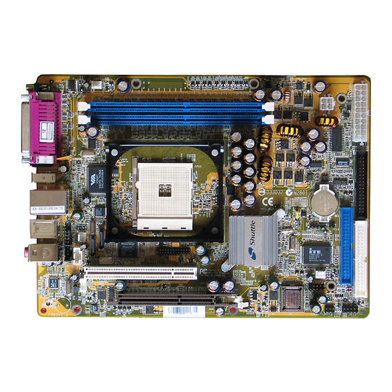
1.2 Item Checklist Check all items with you FN85 mainboard to make sure nothing is missing. The complete package should include: J P 2 FAN1 DIMM1 DIMM2 C N 6 A T A 1 VT6307 - One piece of Shuttle FN85 Mainboard... -
Page 12: Features
2 FEATURES FN85 mainboard is carefully designed for the demanding PC user who wants high perfor- mance and maximum intelligent features in a compact package. 2.1 Specifications - CPU Support AMD Athlon 64 with 200MHz FSB clock on 754-pins SMT Socket. - Page 13 - I/O Interface Provides a variety of I/O interfaces: Ø 1 Floppy interface for 3.5-inch FDD with 720KB, 1.44MB, or 2.88MB format or for 5.25-inch FDD with 360K or 1.2MB format. Ø 1 Printer Port. Ø 1 DB9 serial port 16550 UART compatible. Ø...
-
Page 14: System Bios
- System BIOS Provides licensed Award BIOS V6.0 PG on 4Mb Flash core and supports Green PC, Desktop Management Interface (DMI). - Form Factor System board conforms to Small form factor ATX specification. Board dimension: 254mm X185mm. - Advanced Features Ø... -
Page 15: Hardware Installation
Then follow these steps designed to guide you through a quick and correct installation of your system. 3.1 Step-by-Step Installation Accessories Of FN85 LAN & USB 2.0 Connectors VT6307 Chipset PS/2 Keyboard/Mouse Connectors... -
Page 16: Step 1 Install The Cpu
Step 1 Install the CPU: 1. Locate the CPU ZIF (Zero Insertion Force) socket on the upper-right sector of your mainboard (between the back-panel connectors and the DIMM memory slots). 2. Pull the CPU ZIF socket lever slightly sideways away from the socket to unlock the lever, and then bring it to an upwardly vertical position. -
Page 17: Step 2 Set Jumpers
Step 2. Set Jumpers This mainboard is jumperless! The default jumper settings have been set for the common usage standard of this mainboard. Therefore, you do not need to reset the jumpers unless you require special adjustments as any of the following cases: Clear CMOS For first-time DIY system builders, we recommend that you do not change the... -
Page 18: Step 4 Install Peripherals In System Case
Step 4 Install Internal Peripherals in System Case Before you install and connect the mainboard into your system case, we recommend that you first assemble all the internal peripheral devices into the computer housing, including but not limited to the hard disk drive (IDE/ HDD), floppy disk drive (FDD), CD-ROM drive, and ATX power supply unit. -
Page 19: Step 5 Mount The Mainboard On The Computer Chassis
Step 5 Mount the Mainboard on the Computer Chassis 1. You may find that there are a lot of different mounting hole positions both on your computer chassis and on the mainboard. To choose correct mounting holes, the key point is to keep the back-panel of the mainboard in a close fit with your system case, as shown below. -
Page 20: Step 6 Connect Front Panel Switches/Leds/Speaker/Usb
Step 6 Connect Front Panel Switches/LEDs You can find there are several different cables already existing in the system case and originatinting from the computer's front-panel devices (HDD LED, Power LED,or Reset Switch devices etc.) These cables serve to connect the front-panel switches and LEDs connectors to the mainboard's front-panel con- nectors group, as shown below. -
Page 21: Step 7 Connect Ide, Floppy And Serial Ata Disk Drives
Step 7 Connect IDE, Floppy and Serial ATA Disk Drives 1. IDE cable connector IDE1 IDE2 2. Floppy cable connector FLP1 3. Serial ATA connector Serial ATA ATA1 ATA2 - 17 -... -
Page 22: Step 8 Connect Other Internal Peripherals
Step 8 Connect Other Internal Peripherals 1. Wireless KB/MS Header (JP2) Wireless KB/MS 2. CD-IN(CN2), AUX_IN(CN7), MINI CD-IN(CN6) Connectors CD-IN Mini CD-IN AUX-IN CN7 3. IrDA Header (JP5) IrDA Header - 18 -... -
Page 23: Step 9 Connect The Power Supply
4. DUAL USB Header (JP3) 5. EXT. SMBUS & GPI Header (JP14 & JP15) JP15 JP14 Step 9 Connect the Power Supply 1. System power connector (CN5/ATX1) ATX12V ATX1 ATXPWR - 19 -... -
Page 24: Step 10 Install Add-On Cards In Expansion Slots
Step 10 Install Add-on Cards in Expansion Slots 1. PCI Card 2. AGP Card Step 11 Connect External Peripherals to Back-Panel You are now ready to put the computer case back together and get on to the external peripherals connections to your system's back-panel. 1. -
Page 25: Step 12 First Time System Boot Up
Step 12 First Time System Boot Up To assure the completeness and correctness of your system installation, you may check the above installation steps once again before you boot up your system for the first time. 1. Insert a bootable system floppy disk (DOS 6.2x, Windows 95/98/NT, or others) which contains FDISK and FORMAT utilities into the FDD. -
Page 26: Step 13 Install Drivers & Software Components
2000/ME/XP/NT operating systems only. Make sure your operating system is already installed before running the drivers installation CD-ROM programs. 1. Insert the FN85 bundled CD-ROM into your CD-ROM drive. The autorun program will display the drivers main installation window on screen. -
Page 27: Jumper Settings
3.2 Jumper Settings Several hardware settings are made through the use of mini jumpers to connect jumper pins on the mainboard. Pin #1 could be located at any corner of each jumper, you just find the location with a white right angle which stands for pin 1#. -
Page 28: Jumpers & Connectors Guide
Jumpers & Connectors Guide Use the mainboard layout on page 11 to locate CPU socket, memory banks, expansion slots, jumpers and connectors on the mainboard during the instal- lation. The following list will help you to identify jumpers, slots, and connec- tors along with their assigned functions: B7~B8 B5~B6... - Page 29 Back Panel Connectors COM1 : Serial port PRN1 : Print Port OPT1/2 : SPDIF IN/OUT Ports : 1394 Port LAN1 : LAN Port USB1 : 2 X USB (2.0/1.1) (Universal Serial Bus) ports : PS/2 mouse port : PS/2 keyboard port CENTER/BASS : 5-1 Channel Center/Bass Port Rear-Out : 5-1 Channel Rear-Out Port...
-
Page 30: Clear Cmos Setting (Jp11)
Jumpers Clear CMOS Setting (JP11) JP11 is used to clear CMOS data. Clearing CMOS will result in the perma- nently erasing previous system configuration settings and the restoring origi- nal (factory-set) system settings. Pin 1-2 (Default) Clear CMOS Pin 2-3 (Clear CMOS) JP11 Step 1. -
Page 31: Back-Panel Connectors
Back-Panel Connectors COM1 Port COM1 Port Connector This mainboard can accommodate one serial device on COM1. Attach a serial device cable to the DB9 serial port COM1 at the back-panel of your computer. Parallel Port Parallel Port Connector One DB25 female parallel connector is located at the rear panel of the mainboard. -
Page 32: Ps/2 Keyboard & Ps/2 Mouse Connectors
PS/2 Keyboard & PS/2 Mouse Connectors PS/2 Mouse Two 6-pin female PS/2 keyboard & Mouse connectors are located at the rear panel of the mainboard. Depend- ing on the computer housing you use (desktop or tower), the PS/2 Mouse con- nector is situated at the top of the PS/2 Keyboard connector when the mainboard is laid into a desktop, as op-... -
Page 33: Front-Panel Connectors Atx Power On/Off Switch Connector (Pwon)
Front-Panel Connectors ATX Power On/Off Switch Connector (PWON) The Power On/Off Switch is a momentary type switch used for turning on or off the system ATX power supply. Attach the connector cable from the Power Switch to the 2-pin (PWON) header on the mainboard. Front Panel JP12 Note : Please notice all the LED connectors are directional. -
Page 34: Green Led/ Power Led Connector (Gled/Pwr_Led)
Green LED/ Power LED Connector (GLED/PWR_LED) This header is dual color LED function. Dual color LED function is defined by either Power LED or Green LED, the header can be in these states. The Green LED indicates that the system is currently in one of the power saving mode (Doze/Standby/Suspend). -
Page 35: Front Panel Audio/ Usb/ 1394 Connector (Jp9)
Front Panel AUDIO/ USB/ 1394 Connector (JP9) Port JP9 can be used to connect special device. N/C 26 25 KEY FOUTL 23 FRONTLAMP FRONTRAMP FOUTR LINE_IN_R 20 19 LINE_IN_L MIC_PWR 18 17 MIC_SIGN GND 16 15 GND TPB- 14 13 TPB+ KEY 12 11 GND TPA- 10... -
Page 36: Internal Peripherals Connectors Enhanced Ide And Floppy Connectors
Internal Peripherals Connectors Enhanced IDE and Floppy Connectors The mainboard features two 40-pin dual-channel IDE device connectors (IDE1/ IDE2) providing support for up to four IDE devices, such as CD-ROM and Hard Disk Drives (H.D.D.). This mainboard also includes one 34-pin floppy disk con- troller (FDC) to accommodate the Floppy Disk Drive (FDD). -
Page 37: Other Connectors Atx Power Supply Connectors (Atx1/Cn5)
Other Connectors ATX Power Supply Connectors (ATX1/CN5) This motherboard uses 20-pin ATX power header (ATX1), and comes with the other one header (CN5). Please make sure you plug each in the right direction. It is essential to have these two power supply connectors plugged or your sys- tem won't boot up. -
Page 38: Cpu And System Fan Connectors - Fan1/2/3
CPU and System Fan Connectors - FAN1/2/3 The mainboard provides four onboard 12V cooling fan power connectors to support CPU (FAN1), Chipset (FAN2) or System/AGP (FAN3) cooling fans. +12V SENSE FAN1 FAN1/2/3 with rotate sense. Note : Both cable wiring and type of plug may ary , which depends on the fan maker. -
Page 39: Cd_In Connector (Cn2) (Black)
CD_IN Connector (CN2) (Black) Port CN2 is used to attach an audio connector cable from the CD-ROM drive. CD-IN 1 2 3 4 CD_IN Right CD_IN Left Pin Assignments: 1=CD-IN Left 2=Ground 3=Ground 4=CD-IN Right AUX_IN Connector (CN7) (White) Port CN7 (White) can be used to connect stereo audio inputs from CD-ROM, TV-tuner or MPEG card. -
Page 40: Ext. Gpi Header (Jp15)
EXT. GPI Header (JP15) The GPI supports user-defined function names. This means that the functions inside the platform-independent code can be called anything. The user defines the linking function names in the GPI header file. JP15 Pin Assignments: 1=5V_DUAL 2=KEY 3=GND 4=GPIO6 JP15... -
Page 41: Irda Header (Jp5)
IrDA Header (JP5) If you have an Infrared device, this mainboard can implement IR transfer func- tion. To enable the IR transfer function, follow these steps: IrDA Header Pin Assignments: 1=N/C 2=KEY 3=VCC 4=GND 5=IRTX 6=IRRX EXT. SMBUS Header (JP14) The System Management Bus may share the same host device and physical bus with I²C components provided that the electrical and timing specifications of this document are adhered to. -
Page 42: System Memory Configuration
3.3 System Memory Configuration The FN85 mainboard has two 184-pin DIMM slots that allow you to install from 64MB up to 2GB of system memory. Each 184-pin DIMM (Dual In-line Memory Module) Slot can accommodate 64MB, 128MB, 256MB, 512MB, and 1GB of PC2100, PC2700 or PC3200 compliant 2.6V single (1 Bank) or double (2 Bank) side 64-bit wide data path DDR SDRAM modules. -
Page 43: Software Utility
4 SOFTWARE UTILITY 4.1 Mainboard CD Overview Note : The CD contents attached in FN85 mainboard are subject to change without notice. To start your mainboard CD disc, just insert it into your CD-ROM drive and the CD AutoRun screen should appear. If the AutoRun screen does not appear, double click or run D:\Autorun.exe (assuming that your CD-ROM drive is... -
Page 44: Install Mainboard Software
Insert the attached CD into your CD-ROM drive and the CD AutoRun screen should appear. If the AutoRun screen does not appear, double click on Autorun icon in My Computer to bring up Shuttle Mainboard Software Setup screen. Select using your pointing device (e.g. mouse) on the "Install Mainboard Software"... -
Page 45: A Install Nvidia Chipset Driver
4.2.A Install nVIDIA Chipset System Driver Select using your pointing device (e.g. mouse) on the "Install nVIDIA Chipset Driver" bar to install chipset system driver. Once you made your se- lection, a Setup window run the installation automatically. When the copying files is done, make sure you reboot the system to take the installation... -
Page 46: C Install Silicon Siicfg
4.2.C Install SiICfg Utility Select using your pointing device (e.g. mouse) on the “Install SiICfg Utility " bar to installation Silicfg Utility . Once you made your se- lection, a Setup window run the installation automatically. When the copying files is done, make sure you reboot the system to take the installation... -
Page 47: View The User's Manual
Insert the attached CD into your CD-ROM drive and the CD AutoRun screen should appear. If the AutoRun screen does not appear, double click on AutoRun icon in My Computer to bring up Shuttle Mainboard Software Setup screen. Select using your pointing device (e.g. mouse) on the “Manual" bar. -
Page 48: Bios Setup
5 BIOS SETUP FN85 BIOS ROM has a built-in Setup program that allows users to modify the basic system configuration. This information is stored in battery-backed RAM so that it retains the Setup information even if the system power is turned off. -
Page 49: The Main Menu
5.2 The Main Menu Once you enter the AwardBIOS(tm) CMOS Setup Utility, the Main Menu will appear on the screen. The Main Menu allows you to select from several setup functions and two exit choices. Use the arrow keys to select among the items and press <Enter> to accept and enter the sub-menu. - Page 50 PnP / PCI Configurations This entry appears if your system supports PnP / PCI. PC Health Status This entry shows the current system temperature, Voltage, and FAN speed. Frequency/Voltage Control Use this menu to specify your settings for frequency control. Load Fail-Safe Defaults Use this menu to load the BIOS default values for the minimal/stable performance of your system to operate.
-
Page 51: Standard Cmos Features
Standard CMOS Features The items in Standard CMOS Setup Menu are divided into 10 catego- ries. Each category includes no, one or more than one setup items. Use the arrow keys to highlight the item and then use the <PgUp> or <PgDn>... - Page 52 IDE Secondary Slave Options are in its sub menu. Press <Enter> to enter the sub-menu of detailed options. Drive A/Drive B Select the type of floppy disk drive installed in your system. Ø The choice: None, 360K, 5.25 in, 1.2M, 5.25 in, 720K, 3.5 in, 1.44M, 3.5 in, or 2.88M, 3.5 in.
- Page 53 Access Mode Choose the access mode for this hard disk. Ø The choice: CHS, LBA, Large, or Auto. Capacity Disk drive capacity (Approximated). Note that this size is usually slightly greater than the size of a formatted disk given by a disk check- ing program.
-
Page 54: Advanced Bios Features
Advanced BIOS Features This section allows you to configure your system for basic operation. You have the opportunity to select the system's default speed, boot-up sequence, keyboard operation, shadowing, and security. BIOS Write Protect The item allows you to enable/disable the Bios Write Protect. Ø... - Page 55 CPU Internal Cache All processors that can be installed in this mainboard use internal level 1 (L1) cache memory to improve performance. Leave this item at the default value for better performance. Ø The choice: Enabled or Disabled. External Cache Most processors that can be installed in this system use external level 2 (L2) cache memory to improve performance.
-
Page 56: Gate A20 Option
Gate A20 Option This entry allows you to select how the gate A20 is handled. The gate A20 is a device used for above 1MByte of address memory. Initially, the gate A20 was handled via a pin on the keyboard. Today, while a keyboard still provides this support, it is more common and much faster in setting to Fast for the system chipset to provide support for gate A20. - Page 57 APIC Mode Selects enable/disable IO APIC function Ø The choice: Enabled or Disabled. MPS Version Control For OS Selects the operating system multiprocessor support version. Ø The choice: 1.1 or 1.4 OS Select For DRAM > 64MB Selects the operating system that is running with greater than 64MB of RAM in the system.
-
Page 58: Advanced Chipset Features
Advanced Chipset Features This section allows you to configure the system based on the specific features of the installed chipset. This chipset manages bus speeds and access to sys- tem memory resources, such as DRAM and the external cache. It also coor- dinates communications between the conventional ISA bus and the PCI bus. - Page 59 AGP OverClock in MHz This item selects the AGP OverClock in MHz. Ø The choice: 66~100. AGP Aperture Size(MB) Select the size of Accelerated Graphics Port(AGP) aperture. The aperture is a portion of the PCI memory address range dedicated to graphics memory address space.
- Page 60 Special I/O for PCI Card This item enable/disable the Special I/O for PCI Card. Ø The choice: Disabled or Enable. Base I/O Address This item allows you to set the Base I/O Address. Ø The Choice: 0000 ~ FFFF I/O Length This item allows you to set the I/O Length.
-
Page 61: Integrated Peripherals
Integrated Peripherals Onboard IDE Device Options are in its sub-menu. Press <Enter> to enter the sub-menu of detailed options. OnChip IDE Channel0,1 The chipset contains a PCI IDE interface with support to two IDE chan- nels. Select Enabled to activate the primary IDE interface. select Disabled to deactivate this interface. - Page 62 IDE HDD Block Mode Block mode is also called block transfer, multiple commands, or mul- tiple sector read/write. If your IDE hard drive supports block mode(most new drivers do), select Enabled for automatic detection of the optimal number of block read/write per sector the drive can support. Ø...
- Page 63 Onboard FDC Controller This item specifices onboard floopy disk drive controller. This setting allows you to connect your floopy disk drives to the onboard floopy connector. Ø The Choice: Enable or Disabled. Onboard Serial Port1 This option is used to assign the I/O address and interrupt request(IRQ) for the onboard serial port1(COM1).
-
Page 64: Power Management Setup
Power Management Setup The Power Management Setup allows you to configure your system to most effectively saving energy while operating in a manner consistent with your own style of computer use. ACPI Function This item allows Enable the Advanced Configuration and Power Man- agement (ACPI) Ø... - Page 65 Video Off Method This determines the manner in which the monitor is blanked. V/H SYNC+Blank This selection will cause the system to turn off the vertical and horizontal synchronization ports and write blanks to the video buffer. Blank Screen This option only writes blanks to the video buffer.
- Page 66 USB Resume From S3 If you are using a USB keyboard, and the ACPI suspend type is set to S3, you can enable this item to allow a keystroke to wake up the system from power saving mod. Ø The choice: Enabled, Disabled. Power-On by Alarm When set to Enabled, the following three fields become available and you can set the month, date (day of the month), hour, minute and...
-
Page 67: Pnp/Pci Configuration
PnP/PCI Configurations This section describes the configuration of PCI bus system. PCI or Personal Computer Interconnection is a system which allows I/O devices to operate at the speed CPU itself keeps when CPU communicating with its own special components. This section covers some very technical items, and it is strongly recommended that only experienced users should make any changes to the default settings. - Page 68 IRQ Resources When resources are controlled manually, assign each system interrupt a type, depending on the type of device using the interrupt. IRQ3/4/5/7/9/10/11/12/14/15 assigned This item allows you to determine the IRQ assigned to the ISA bus and is not available to any PCI slot. Legacy ISA for devices is compliant with the original PC AT bus specification;...
-
Page 69: Pc Health Status
PC Health Status CPU Fan Speed Control The item defines the fan speed control features. Ø The choice: Smart Fan, Ultra-Low, Low, Mid, or Full. This feature is controlled via BIOS, in which the CPU fan rotational speed sensing/control is governed by CPU temperature setting pre- selected in BIOS. - Page 70 Fan Speed Up When CPU Temp Enabled 4 phase smart control to the Selected fan. This feature ranges from 40 C to 52 C, in an increment of 4 Ø The choice: 40 C, 44 C, 48 C, or 52 Warning : It is Strongly recommanded to disable CPU Fan AutoGuardian feature, if you wish to use other fan...
-
Page 71: Frequency/Voltage Control
Frequency/Voltage Control CPU Voltage Select This item allows you to set the CPU Voltage. Ø The choice: 0.800V, 0.825V, 0.850V, 0.875V, 0.900V, 0.925V, 0.950V, 0.975V, 1.000V, 1.025V, 1.050V,1.075V, 1.100V, 1.125V, 1.150V, 1.175V, 1.200V, 1.225V, 1.250V, 1.275V, 1.300V, 1.325V, 1.350V, 1.375V, 1.400V, 1.425V, 1.450V, 1.475V, 1.500V, 1.525V, 1.550V, 1.600V, 1.650V, 1.700V or Auto. -
Page 72: Load Fail-Safe Defaults
Load Fail-Safe Defaults When you press <Enter> on this item, you will get a confirmation dialog box with a message similar to: Load Fail-Safe Defaults (Y/N) ? N Pressing 'Y' loads the BIOS default values for the most stable, minimal performance system operations. -
Page 73: Save & Exit Setup
New Password Setting: 1. While pressing <Enter> to set a password, a dialog box appears to ask you enter a password. 2. Key in a new password. The password can not exceed eight charac- ters. 3. System will request you to confirm the new password again. 4.
Need help?
Do you have a question about the FN85 and is the answer not in the manual?
Questions and answers