
Related Manuals for Shuttle FV24


Summary of Contents for Shuttle FV24
- Page 1 FV24 FC-PGA/FC-PGA2 Celeron and FC-PGA/FC-PGA2 Pentium III Processor Based Main Board User's Manual...
- Page 2 FV24 FC-PGA/FC-PGA2 Celeron and FC-PGA/FC-PGA2 Pentium III processor based Mainboard Manual Version 3.0 Disclaimer This company makes no representations or warranties regarding the contents of this manual. Information in this manual has been carefully checked for reliability; however, no guarantee is given as to the correctness of the contents.
-
Page 3: Table Of Contents
TABLE OF CONTENTS WHAT’S IN THE MANUAL ..............5 Quick Reference ....................5 About This Manual .................... 5 1 INTRODUCTION ................. 6 1.1 TO DIFFERENT USERS ................6 First-Time DIY System Builder ..............6 Experienced DIY User ................6 System Integrator ..................6 1.2 ITEM CHECKLIST .................. - Page 4 3.2 JUMPER SETTINGS .................. 25 JUMPER & CONNECTOR GUIDE ............26 Jumpers Clear CMOS (J9) ................... 28 USB Port 3/4 Power-On Setting (J10)............. 28 Back-Panel Connectors PS/2 Keyboard & PS/2 Mouse Connectors ..........29 VGA Port Connector................29 COM1 Port Connector ................29 Parallel Port Connector................29 TV-Out S/Video Port Connectors ............
- Page 5 Other Connectors ATX Power Supply Connector (JWR1) ............ 37 Cooling FAN Connectors for CPU FANs (FAN1/FAN2) ......37 Optional Modem Riser Adapter Connector (JP5) ........38 Audio Connector CD_In (SJP1) .............. 38 PCI Riser pin (J4) ................... 38 3.3 SYSTEM MEMORY CONFIGURATION ............39 Install Memory ..................
- Page 6 5 BIOS SETUP ..................50 5.1 ENTER THE BIOS ..................50 5.2 THE MAIN MENU ..................51 STANDARD CMOS FEATURES ..............53 ADVANCED BIOS FEATURES ..............57 ADVANCED CHIPSET FEATURES ............61 INTEGRATED PERIPHERALS ..............65 POWER MANAGEMENT SETUP .............. 68 PNP/PCI CONFIGURATION ...............
-
Page 7: What's In The Manual
WHAT’S IN THE MANUAL Quick Reference Hardware Installation >> Step-by-Step ..........Page 12 Jumper Settings >> A Closer Look ............Page 25 Software Utility >> How to Install ............Page 40 BIOS Setup >> How to Configure ............Page 50 About This Manual For First-Time DIY System Builder ............ -
Page 8: Introduction
1 INTRODUCTION 1.1 To Different Users First-Time DIY System Builder Experienced DIY User System Integrator - 6 -... -
Page 9: Item Checklist
1.2 Item Checklist K B M S 1 F A N 1 P r o S a v a g e 92 4 8B F - 7 3 PL 1 3 3 99 2 3 CA9 3 02 2 0 86 0 4 N F C O C A 00 1 7 C 6 2 9 05 . - Page 10 Ø Ø Ø Ø Ø Ø Ø - 8 -...
-
Page 11: Features
2 FEATURES 2.1 Specifications CPU Support Chipset Jumperless CPU Configuration Integrated Graphics Controller AC'97 Link for Audio and Telephony CODEC - 9 -... - Page 12 Versatile Memory Support PCI Expansion Slots I/O Interface Ø Ø Ø Ø Ø Ø Ø Ø Ø Ø Ø 4 USB Interface Onboard Ø PCI Bus Master IDE Controller Onboard - 10 -...
- Page 13 ATX Power Supply Connector Advanced Configuration and Power Interface System BIOS Flex ATX Form Factor Advanced Features Ø Ø Intelligent Features Ø Ø Ø - 11 -...
-
Page 14: Hardware Installation
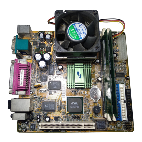
Before removing or installing any of these devices including CPU, DIMMs, Add-On Cards, Cables, please make sure to unplug the onboard power connector. This section outlines how to install and configure your FV24 mainboard. Refer to the following mainboard layout to help you identify various jumpers, connectors, slots, and ports. -
Page 15: Step 1 Install The Cpu
Step 1 Install the CPU: F C -P G A 2 C P U F C -P G A C P U I N T EL ‘ 00 A 4 V 10 5 50 2C - 03 43 Q E J0 E S ‘... -
Page 16: Step 2 Set Jumpers
Step 2. Set Jumpers Step 3. Install SDRAM System Memory - 14 -... -
Page 17: Step 4 Install Internal Peripherals In System Case
Step 4 Install Internal Peripherals in System Case - 15 -... -
Page 18: Step 5 Mount The Mainboard On The Computer Chassis
Step 5 Mount the Mainboard on the Computer Chassis - 16 -... -
Page 19: Step 6 Connect Front-Panel Switches/Leds/Speaker/Audio/Usb
Step 6 Connect Front-Panel Switches/LEDs/Speaker/Audio/USB connectors U SB2 - 17 -... - Page 20 - 18 -...
-
Page 21: Step 7 Connect Ide & Floppy Disk Drives
MIC-IN MIC-VC C AGN D R SP E AKER -OUT L S PEA K ER-OU T USB Port 4 USB Port 3 Step 7 Connect IDE & Floppy Disk Drives ID E1 ID E2 - 19 -... -
Page 22: Step 8 Connect Other Internal Peripherals
Step 8 Connect Other Internal Peripherals Step 9 Connect Power Supply - 20 -... -
Page 23: Step 10 Install Add-On Cards In Expansion Slots
Step 10 Install Add-on Cards in Expansion Slots Step 11 Connect External Peripherals to Back-Panel foxc on n - 21 -... - Page 24 f ox c on n - 22 -...
-
Page 25: Step 12 First Time System Boot Up
Step 12 First Time System Boot Up - 23 -... -
Page 26: Step 13 Install Driver & Software Components
Step 13 Install Driver & Software Components - 24 -... -
Page 27: Jumper Settings
3.2 Jumper Settings - 25 -... -
Page 28: Jumper & Connector Guide
Jumper & Connector Guide B2~B3 B4~B6 B7~B8 B9~B10 C1~C6 CPU/Memory/Expansion Slots Jumpers Back-Panel Connectors - 26 -... - Page 29 Front-Panel Connectors (JP3, JP4, JP2, and USB2) Internal Peripherals Connectors Other Connectors: - 27 -...
-
Page 30: Jumpers Clear Cmos (J9)
Jumpers Clear CMOS (J9) USB Port 3/4 Power-On Setting (J10) - 28 -... -
Page 31: Back-Panel Connectors Ps/2 Keyboard & Ps/2 Mouse Connectors
Back-Panel Connectors PS/2 Keyboard & PS/2 Mouse Connectors f ox c on n VGA Port Connector COM1 Port Connector Parallel Port Connector - 29 -... -
Page 32: Tv-Out S/Video Port Connectors
Optional S/Composit Video TV-Out Connectors f ox c on n IEEE 1394 Port Connectors 10/100 base-T LAN Port Connector USB1/USB2 Port Connectors Line-In - 30 -... -
Page 33: Line-Out
Line-Out - 31 -... -
Page 34: Front-Panel Connectors Atx Power On/Off Switch Connector (Pwon)
Front-Panel Connectors ATX Power On/Off Switch Connector (PWON) Note : EPMI Connector (EPMI) - 32 -... -
Page 35: Green Led / Power Led Connector (Gled / Pled)
Green LED/Power LEC Connector (GLED/PLED) HDD LED Connector (HDLED) - 33 -... -
Page 36: Pwr Led Connector (Pled)
PWR LED Connector (PLED) Hardware Reset Connector (RST) Spk-Out and Mic-In Header (JP2) - 34 -... -
Page 37: Extended Usb Header (Usb2)
Extended USB Header (USB2) USB Port 4 2 4 6 8 10 1 3 5 7 9 Port U SB2 - 35 -... -
Page 38: Internal Peripherals Connectors Enhanced Ide Ports And Floppy Connectors
Internal Peripherals Connectors Enhanced IDE Ports and Floppy Connector ID E1 ID E2 - 36 -... -
Page 39: Other Connectors Atx Power Supply Connector (Jwr1)
Other Connectors ATX Power Supply Connector (JWR1) Cooling Fan Connectors for CPU (FAN1/2) FAN1 - 37 -... -
Page 40: Optional Modem Riser Adapter Connector (Jp5)
Optional Modem Riser Adapter Connector (JP5) 2 4 6 8 10 1 3 5 7 9 Audio Connector CD _In (SJP1) PCI Riser pin (J4) - 38 -... -
Page 41: System Memory Configuration
3.3 System Memory Configuration Install Memory: Upgrade Memory: - 39 -... -
Page 42: Software Utility
4 SOFTWARE UTILITY 4.1 Mainboard CD Overview Note: Navigation Bar Description: F Install Mainboard Software F Install VIA Hardware Monitor F LAN Driver Installation F Manual F Browse this CD F Quit - 86 - - 40 -... -
Page 43: Install Mainboard Software
4.2 Install Mainboard Software My Computer Mainboard Software Setup Install Mainboard Software Mainboard Software - 87 - - 41 -... -
Page 44: Install Via 4 In 1, Agp, Audio Driver
Install VIA 4 in 1, AGP, and Audio Device Driver [4.2.A] Install VIA Driver [4.2.B] Install AGP Device Software [4.2.C] "Install Audio Device Software" reboot - 42- - 88 -... -
Page 45: Install Via Hardware Monitor And Lan Drivers
4.3 Install VIA Hardware Monitor and LAN drivers My Computer Mainboard Software Setup Install VIA Hardware Monitor LAN Driver Installation reboot Note: When Install LAN driver, please confirm your OS and correctly install driver. If your OS is win 9X/NT, please take the following chapt description "Install LAN Software"... -
Page 46: Install Lan Software
4.4 Install LAN Software Install WIN98 LAN driver The LAN Device Driver can't install automatically, you need double click on My Computer -> Control Pnael -> System icon to bring up System Proper- ties screen. Select tab "Device Manager". You will find a yellow "?" mark at PCI Ethernet Controller, that means the driver is not recognize. - Page 47 Please choose "Display a list of the drivers in a specific location, so you can select the driver you want" to the manual install driver, and click on "Next" bar to continue. Select "Network adapters" bar for LAN device and click on "Next" bar to con- tinue.
- Page 48 Select "Realtek RTL8139/810X Family PCI Fast Ethernet NIC" to install, and then click on "OK". Make sure "Realtek RTL8139/810X Family PCI Fast Ethernet NIC" driver, and click on "Next". Then the system will do the setup procddure automatically. Completing the upgrade device driver, and click on "Finish"...
-
Page 49: Install Winnt Lan Driver
- 47 -... - Page 50 - 48 -...
-
Page 51: View The User's Manual
Then Online Information windows will appear on the screen. Click on the “Install Acrobe Reader” bar if you need to install acrobe reader. Then click on "FV24 Manual" bar to view FV24 user's manual. - 90 - - 49 -... -
Page 52: Bios Setup
5 BIOS SETUP 5.1 Enter the BIOS - 50 -... -
Page 53: The Main Menu
5.2 The Main Menu Setup Items Standard CMOS Features Advanced BIOS Features Advanced Chipset Features - 51 -... - Page 54 Integrated Peripherals Power Management Setup PnP / PCI Configuration PC Health Status Frequency/Voltage Control Load Fail-Safe Defaults Load Optimized Defaults Supervisor / User Password Save & Exit Setup Exit Without Saving - 52 -...
-
Page 55: Standard Cmos Features
Standard CMOS Features - 53 -... - Page 56 Ø Ø Ø Ø Ø Ø Ø Ø - 54 -...
- Page 57 IDE Adapters Ø Ø Ø Ø The following options are selectable only if the 'IDE Primary Master' item is set to 'Manual' Ø Ø - 55 -...
- Page 58 Ø Ø Ø - 56 -...
-
Page 59: Advanced Bios Features
Advanced BIOS Features Ø Ø - 57 -... - Page 60 Ø Ø Ø Ø Ø Ø Ø Ø - 58 -...
- Page 61 Ø Ø Ø Ø Ø Ø - 59 -...
- Page 62 Ø Ø Ø - 60 -...
-
Page 63: Advanced Chipset Features
Advanced Chipset Features Ø Ø Ø - 61 -... - Page 64 Ø Ø Ø Ø Ø Ø Ø - 62 -...
- Page 65 Ø Ø Ø Ø Ø Ø Ø Ø - 63 -...
- Page 66 Ø Ø Ø Ø Ø - 64 -...
-
Page 67: Integrated Peripherals
Integrated Peripherals Ø Ø Ø - 65 -... - Page 68 Ø Ø Ø Ø Ø Ø Ø - 66 -...
- Page 69 Ø Ø Ø Ø Ø Ø Ø Ø Ø Ø - 67 -...
-
Page 70: Power Management Setup
Power Management Setup Ø - 68 -... - Page 71 Ø Ø Ø Ø Ø Ø - 69 -...
- Page 72 Ø Ø Ø Ø Ø - 70 -...
- Page 73 Ø Ø Ø Ø Ø Ø Ø Ø - 71 -...
- Page 74 Ø Ø Ø Ø Ø - 72 -...
-
Page 75: Pnp/Pci Configuration
PnP/PCI Configuration Ø Ø - 73 -... - Page 76 Ø Ø Ø Ø - 74 -...
- Page 77 Ø Ø - 75 -...
-
Page 78: Pc Health Status
PC Health Status - 76 -... -
Page 79: Frequency/Voltage Control
Frequency/Voltage Control Ø Ø - 77 -... -
Page 80: Load Fail-Safe Defaults
Load Fail-Safe Defaults Load Optimized Defaults - 78 -... -
Page 81: Set Supervisor Password
Supervisor/User Password Setting - 79 -... -
Page 82: Save & Exit Setup
Save & Exit Setup Exit Without Saving - 80 -...
Need help?
Do you have a question about the FV24 and is the answer not in the manual?
Questions and answers