Table of Contents
Advertisement
Quick Links
Advertisement
Table of Contents

Related Manuals for INVT iMars BG12KTR


Summary of Contents for INVT iMars BG12KTR
- Page 1 Operation Manual iMars INVT Solar Technology (Shenzhen) Co., Ltd.
-
Page 3: Preface
Preface The manual is intended to provide detailed information of product information, installation, application, trouble shooting, precautions and maintenance of iMars series grid-tied solar inverters. The manual does not contain all the information of the photovoltaic system. Please read this manual carefully and follow all safety precautions seriously before any moving, installation, operation and maintenance to ensure correct use and high performance of operation on the inverter. -
Page 4: Table Of Contents
iMars grid-tied solar inverters Content Contents Preface ..............................1 Contents ............................. 2 1 Safety precautions ......................... 5 1.1 Icons ............................6 1.2 Safety guidelines ........................6 1.2.1 Delivery and installation .......................7 1.2.2 Grid-tied operation .........................8 1.2.3 Maintenance and inspection......................8 1.2.4 What to do after scrapping......................9 2 Product overview ......................... - Page 5 iMars grid-tied solar inverters Content 4.2.3 Connection cables........................... 24 4.2.4 Miniature circuit breakers......................24 4.3 Mechanical installation ......................25 4.3.1 Installation of three-phase inverter ....................25 4.4 Electrical installation......................28 4.4.1 Connection of solar modules ......................29 4.4.2 AC connection of 12kW / 15kW / 17kW / 20kW / 25kW / 30kW inverter ......... 30 5 Operation ............................
- Page 6 iMars grid-tied solar inverters Content 6.4.7 Inverter control ..........................51 6.4.8 Mode settings ..........................52 6.5 Grid Certification Choice ....................... 53 7 Monitoring communication....................... 55 7.1 Standard communication ...................... 56 7.2 Optional communication ....................... 57 7.3 RS485-DRM ports ......................... 58 8 Troubleshooting ..........................
-
Page 7: Safety Precautions
iMars grid-tied solar inverters Safety precautions 1 Safety precautions iMars series grid-tied solar inverters are designed and tested strictly in accordance with relevant international safety standards. As an electrical and electronic device, all relevant safety regulations must be strictly complied during installation, operation, and maintenance. Incorrect use or misuse may result in Injury to the life and personal safety of the operator or other people. -
Page 8: Icons
iMars grid-tied solar inverters Safety precautions 1.1 Icons This manual provides relevant information with icons to highlight the physical and property safety of the user to avoid device damage and physical injury. The icons used in this manual are listed below: Icons Name Instruction... -
Page 9: Delivery And Installation
iMars grid-tied solar inverters Safety precautions Ensure that there is no electromagnetic interference from other electrical and electronic equipments on the installation site. Do not refit the inverter unauthorized. All the electric installation needs to be compliance with the national or local laws and standards. -
Page 10: Grid-Tied Operation
iMars grid-tied solar inverters Safety precautions protective measures, such as protective shoes and work clothes. Only qualified electricians are allowed to install the inverter. Do not put and install the inverter on or close to combustible materials. Keep the installation site away from children and other public places. Remove the metal jewelry such as ring and bracelet before installation and electrical connection to avoid electric shock. -
Page 11: What To Do After Scrapping
iMars grid-tied solar inverters Safety precautions maintenance, temporary warning labels must be placed to warn non-professionals to enter or use fence for isolation. Firstly disconnect all power supplies of the grid to the inverter before any maintenance, and then disconnect the breakers and wait for at least 5 minutes until the inverter is discharged before maintenance. -
Page 12: Product Overview
iMars grid-tied solar inverters Product overview 2 Product overview This chapter mainly describes the appearance, packaging accessories, name plate, technical parameters and other information of iMars grid-tied solar inverters. -
Page 13: Solar Grid-Tied Power Generation System
iMars grid-tied solar inverters Product overview 2.1 Solar grid-tied power generation system The photovoltaic grid-tied power generation system consists of solar modules, grid-tied inverter, metering devices and public grid. Figure 2.1 Application of iMars grid-tied solar inverters Grid-tied solar inverter is the core of photovoltaic power generation system. The solar energy can be converted into DC electric energy through solar modules and then be changed into sinusoidal AC energy which has the same frequency and phase with the public grid by grid-tied solar inverters, and then be fed to the grid. -
Page 14: Products Appearance
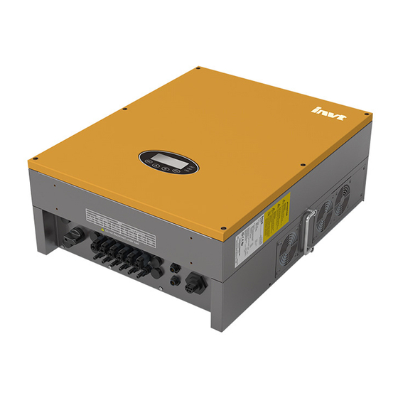
iMars grid-tied solar inverters Product overview Figure 2.2 Type of grid 2.2 Products appearance 2.2.1 Three-phase inverter Figure 2.3 Products appearance of 12~17kW... - Page 15 iMars grid-tied solar inverters Product overview Figure 2.4 Products appearance of 20~30kW Table 2-1 Parts instruction of Three-phase grid-tied solar inverter Name Instruction Cover Operational panel LED indicators, LCD screen and buttons Communication port DRM communication port DC input port For the connection of solar modules Communication port RS485 and EXT communication port...
-
Page 16: Name Plate
iMars grid-tied solar inverters Product overview 2.3 Name plate After receiving, please check the information of name plates are the ordered one. If not, please contact with the supplier as soon as possible. Figure 2.5 Name plate 1 Trademark and product type 2 Model and important technical parameters 3 Certification system of the inverter confirming 4 Serial number, company name and country of origin... -
Page 17: Drm Instruction
iMars grid-tied solar inverters Product overview Icons Instruction TUV certification mark. The inverter is certified by TUV. CE certification mark. The inverter complies with the CE directive. CQC certification mark. The inverter is certified by CQC. EU WEEE mark. Cannot dispose of the inverter as household waste. 2.4 DRM instruction Figure 2.6 DRM label Table 2-2 DRMs instruction... -
Page 18: Models
iMars grid-tied solar inverters Product overview 2.5 Models Table 2-3 Models of iMars grid-tied solar inverter Product name Model Rated output power Three-phase (L1, L2, L3, N, PE) Three-phase grid-tied solar inverter 12kW 12000 W Three-phase grid-tied solar inverter 15kW 15000 W Three-phase grid-tied solar inverter 17kW... -
Page 19: Dimensions And Weight
iMars grid-tied solar inverters Product overview 2.6 Dimensions and weight Figure 2.7 Inverter dimensions Table 2-4 Inverter dimension and net weight Net weight Model (mm) (mm) (mm) (kg) 12kW / 15kW/ 17kW 20kW / 25kW / 30kW Figure 2.8 Paper packages dimension Table 2-5 Packages dimension and gross weight Gross weight Packaging... -
Page 20: Storage
iMars grid-tied solar inverters Storage 3 Storage If the inverter is not put into use immediately, the storage of inverter should meet the following requirements: Do not remove the outer packing. The inverter needs to be stored in a clean and dry place, and prevent the erosion of dust and water vapor. -
Page 21: Installation
iMars grid-tied solar inverters Installation 4 Installation This chapter describes how to install the inverter and connect it to the grid-tied solar system (including the connection between solar modules, public grid and inverter). Read this chapter carefully and ensure all installation requirements are met before installation. Only qualified electricians are allowed to install the inverter. -
Page 22: Unpacking Inspection
iMars grid-tied solar inverters Installation 4.1 Unpacking inspection I Inspect the information of the order and the name plate to ensure the product are the ordered one and no damage to the package. If any problem, contact the supplier as soon as possible. Put the inverter into the package if not used and protect it from humidity and dust. -
Page 23: Before Installation
iMars grid-tied solar inverters Installation Packing list of 20kW / 25kW / 30kW inverter: Figure 4.2 Packing list of 20kW / 25kW / 30kW inverter Table 4-2 Detailed delivery list of 20kW / 25kW / 30kW inverter Name Quantity 20kW / 25kW / 30kW inverter Installation bracket operation manual Communication connector... -
Page 24: Installation Place
iMars grid-tied solar inverters Installation Installation tools Instruction Allen driver Fasten the screws, remove and install AC wiring box Straight screwdriver For AC wiring Megger Measuring insulation performance and impedance Multimeter Check the circuit and AC and DC voltage Electric iron Weld communications cable Wire crimper Crimp DC terminals... - Page 25 iMars grid-tied solar inverters Installation When install more than one inverter, it is necessary to reserve a certain space between the inverters. The left and right spacing is shown as Figure 4.5, and the upper and lower sides of the inverter should have sufficient space to ensure good heat dissipation.
-
Page 26: Connection Cables
iMars grid-tied solar inverters Installation (8) The installation should ensure that the inverter is reliably grounded, and the material of grounded metal conductor should be consistent with the metal material reserved for the grounding of the inverter. Do not remove any part and component of the inverter unintended; otherwise damage to the device and physical injury may occur. -
Page 27: Mechanical Installation
iMars grid-tied solar inverters Installation 4.3 Mechanical installation Since the installation place can be made by different construction materials, the inverter can be installed by different mounting methods. Take the typical installation environment as the example, the manual describes how to install the inverter on concrete wall. And because of different structure, the three-phase inverter has different instillation modes. - Page 28 iMars grid-tied solar inverters Installation Table 4-6 Instruction of installation bracket Installation hole Model A(mm) B(mm) 12kW / 15kW/ 17kW / 20kW / 25kW / 30kW Installation steps of three-phase inverter: (1) Use the wall hanging plate in the packing box to determine the hole position As shown in Figure 4.8.
- Page 29 iMars grid-tied solar inverters Installation Figure 4.10 Install expansion bolts (4) Fix the installation bracket onto the expansion bolts and ensure the installation is firm enough(tightening torque is 13N m) . As shown in Figure 4.11. Figure 4.11 Fix the installation bracket (5) Hang the inverter onto the installation bracket and ensure the installation is firm enough.
-
Page 30: Electrical Installation
iMars grid-tied solar inverters Installation (6) Ensure the inverter is installed properly and tighten the M6X16 bolts into the screw holes on the left and right side of inverter(tightening torque is 4N m). As shown in Figure 4.13. Figure4.13 Installation of M6X16 bolts 4.4 Electrical installation This section proposes to describe detailed electrical installation and related safety instructions. -
Page 31: Connection Of Solar Modules
iMars grid-tied solar inverters Installation 4.4.1 Connection of solar modules Figure 4.15 Connection between DC connector and solar modules Connection steps: (1) Lighting, short-circuit and other protection measures which meet the local electrical safety laws and regulations are needed before the AC connection; Only qualified cables under the local electrical safety laws and regulations are allowed to connect. -
Page 32: Ac Connection Of 12Kw / 15Kw / 17Kw / 20Kw / 25Kw / 30Kw Inverter
iMars grid-tied solar inverters Installation The solar modules connected with the inverter needs to be the configured ones other than some connecting devices without authorized. Otherwise, device damage, unstable operation or fire may occur. (4) Connect the DC connector with the inverter and ensure tightly-fastened; (5) Insert the screw-driver into the hole of the connector to remove the connector form the inverter. - Page 33 iMars grid-tied solar inverters Installation (3) Remove the fixing screws of AC terminal rail, as shown in Figure 4.18. Figure 4.18 Remove fixing screws of the rail (4) Pull out the AC terminal rail as shown in Figure 4.19. Figure 4.19 Pull out the rail (5) Crimp the five wires(L1 L2 L3 N PE) of the three-phase utility grid and the OT terminals firmly to ensure that the conductor of the wire is not exposed, as shown in Figure 4.20;...
- Page 34 iMars grid-tied solar inverters Installation Figure 4.21 Connection of wire and connector (7) Push the AC terminal rail into the inside of the case and fix the rail with screws. Then lock the waterproof cover of the junction box with the fixing screws. The tightening torque is 1.5 N•m. Finally, tighten the waterproof connector to complete the waterproofing of the cable, as shown in Figure 4.22.
-
Page 35: Operation
iMars grid-tied solar inverters Operation 5 Operation This chapter describes detailed operation of the inverter which involves the inspection before operation, grid-tied operation, stopping and daily maintenance of the inverter. -
Page 36: Inspection Before Operation
iMars grid-tied solar inverters Operation 5.1 Inspection before operation Check as follows before operation (including but not limited to): (1) Ensure the installation site meet the requirement mentioned in section 4.2.2 for easy installation, removing, operation and maintenance; (2) Ensure the mechanical installation meet the requirement mentioned in section 4.3; (3) Ensure the electrical installation meet the requirement mentioned in section 4.4;... -
Page 37: Stopping
iMars grid-tied solar inverters Operation 5.3 Stopping Stop the inverter as follows it needs maintenance, inspection and troubleshooting: (1) Switch off the breakers at the AC side; (2) Switch off the integrated DC switch; (3) Switch off the switch on the DC side; (4) Wait at least 5 minutes until the internal parts and components are discharged. -
Page 38: Maintenance Guide
iMars grid-tied solar inverters Operation Maintenance Maintenance Maintenance methods contents cycle Check the fans of three-phase inverter to make sure out of wind is normal, the sound is normal, the fan blades are no cracks, power lines and Maintenance and control signal lines are not damaged. - Page 39 iMars grid-tied solar inverters Operation Figure 5.1 Remove the cooling chamber Figure 5.2 Remove the fan mounting plate (5) Use soft brush or vacuum cleaner to clean the cooling chamber and the fans. (6) Assembly the cooling chamber or fan mounting plate into inverter. (7) Re-install the inverter to its original position as Section 4 of the content.
- Page 40 iMars grid-tied solar inverters Operation (5) Dismantle the fan mounting plate as shown in Figure 5.2. (6) Remove the damaged fans, and replace good fans, connect the power lines and control signal lines, as shown in Figure 5.3. Figure 5.3 Replace fans (7) Assembly the cooling chamber or fan mounting plate into inverter.
-
Page 41: Display Panel
iMars grid-tied solar inverters Display panel 6 Display panel This chapter describes the panel displaying and how to operate on the panel, which involves the LCD display, LED indicators and operation panel. -
Page 42: Led Indicators
iMars grid-tied solar inverters Display panel The operation state and parameters can be attained from the LED indicators and LCD display. The displayed content and parameters can also be set or modified by the operation panel. LCD screen V - p v 1 : 0 0 0 . 0 V I - p v 1 : 0 0 0 . -
Page 43: Operation Panel
iMars grid-tied solar inverters Display panel Inverter state LED indicators Description E012); Green and yellow indicator keeps on, others off. Inverter stand-by. The public grid fault(A001, A003, Warn A004, A005or A006); Fault Yellow indicator blinks in every 0.5s, others off Recoverable fault (1) Inverter stand-by. -
Page 44: Functions Operation
iMars grid-tied solar inverters Display panel Curve Graphic Text Parameter Display Area Display Area Status Area Fault Code Menu Figure 6.2 Main interface The main interface of the LCD screen is shown as the figure above: (1) The curve displays the power changing at the current day; (2) The words on the screen display the current key parameters of the inverter. -
Page 45: History
iMars grid-tied solar inverters Display panel Table 6-2 Monitoring parameters Monitoring content 12kW / 15kW / 17kW 20kW / 25kW / 30kW ● ● Total power produced this day(E-tod) ● ● Total power saved this day($-tod) ● ● Input power(P-in) ●... -
Page 46: Statistics
iMars grid-tied solar inverters Display panel parameters which is shown in figure 6.5. H i s t o r y 2 0 1 2 / 0 1 / 0 5 1 1 : 3 2 : 1 6 A 0 0 5 : G r i d u n d e r f r e q Figure 6.5 History parameters There are 32 history records in total. - Page 47 iMars grid-tied solar inverters Display panel LCD menus: V - pv 1 : 000 . 0 V Setup Menu I - pv 1 : 000 . 0 A Address Date / Time V - pv 2 : 000 . 0 V Keypad PWD Language Cash / price...
- Page 48 iMars grid-tied solar inverters Display panel Table 6-4 Parameters setting Setting item LCD display Instruction Enter into the interface and edit the data R S 4 8 5 A d d r e s s through “ ” or “ ”.
- Page 49 iMars grid-tied solar inverters Display panel Setting item LCD display Instruction Enter into the interface and edit the currency type and cash through “ ” or “ ”. And then press “ENT” again to the S e t u p C a s h T y p e : E U R E U R next line.
- Page 50 iMars grid-tied solar inverters Display panel Setting item LCD display Instruction Input password 0000 The password is needed when enter into the interface of “Set power”. Get the set power P-Lmt password from the supplier if necessary. Mode LmtPower There are 3 submenus: P-Lmt Mode: P.Factor invalid (limited power function is...
- Page 51 iMars grid-tied solar inverters Display panel Setting item LCD display Instruction Input password 0000 Run Param UV Volt OV time UV time UF Freq OV Volt UF time ACUV Volt(phase volt) 184V Password is required when enter into the interface of “Run Param”. Get the ACUV Time password from the supplier if necessary.
- Page 52 iMars grid-tied solar inverters Display panel Setting item LCD display Instruction Input Password 0000 Run Param UV volt 1 OV time 1 UV time 1 UF Freq 1 OV volt 1 UF time 1 ACUV Volt(phase volt) 115V ACUV Time 00.04s ACOV Volt(phase volt) 309V...
-
Page 53: System Information
iMars grid-tied solar inverters Display panel 6.4.5 System Information Press “ ” and “ ” in the main interface to select “System Information”, and then press “ENT” to view the parameters which is shown in figure 6.8. System Information Part No . Cert . -
Page 54: Mode Settings
iMars grid-tied solar inverters Display panel Control item LCD display Instruction Control the “On/Off” through the panel. O n / O f f C t r l Press “ ” and “ ” in the control On/Off interface to select the operation. Press O F F control “ENT”... -
Page 55: Grid Certification Choice
iMars grid-tied solar inverters Display panel 6.5 Grid Certification Choice Power on the inverter by DC input for the first time or after Restore factory settings, it will appear on the LCD screen prompts as follows: S O L A R I N V E R T E R I n i t i a l i n g W a i t i n g >... - Page 56 iMars grid-tied solar inverters Display panel Country Certification Remark Germany VDE0126& AR-N4105 G83/G59 Australia AS4777 Greece VDE0126 Denmark TF321 Holland C10/C11 China Thailand Other VDE0126 Reference Table: Grid Certification and Grid Voltage and Frequency of Some Countries Three-phase Grid Country Certification voltage frequency...
-
Page 57: Monitoring Communication
iMars grid-tied solar inverters Monitoring communication 7 Monitoring communication This chapter describes the communication connection of inverter and monitoring system (Industrial master, private computers, smart phones and so on). -
Page 58: Standard Communication
iMars grid-tied solar inverters Monitoring communication 7.1 Standard communication The standard communication mode of iMars grid-tied solar inverter is RS485 which includes “RS485” and “EXT” ports. The two ports can both communicate with private computers, smart phones and so on. The system monitoring solution are shown as figure 7.1. Figure 7.1 Monitoring system of inverter Table 7-1 Pins on inverter instruction Pin on inverter... -
Page 59: Optional Communication
(2) According to Table 7-1, connect the communication connector pinout and the user's device, make sure the connection is correct; (3) Please download the monitoring software “iMars WinExpert” and its operation instruction on www.invt-solar.com. 7.2 Optional communication The optional communication modes include Ethernet, WiFi, which also need corresponding communication parts and components. -
Page 60: Rs485-Drm Ports
Monitoring communication Please download the connection instruction, operation manual and commissioning tools on website www.invt-solar.com. Note: the optional accessories are not standard-configured. 7.3 RS485-DRM ports Table 7-3 RS485-DRM Pins on inverter instruction Pin on inverter Colour... -
Page 61: Troubleshooting
iMars grid-tied solar inverters Troubleshooting 8 Troubleshooting This chapter describes the fault alarm and fault code for quick troubleshooting. - Page 62 iMars grid-tied solar inverters Troubleshooting Table 8-1 Fault code Fault Message Instruction Fault analysis code PV1 undervoltage A001 Input UV Input undervoltage PV2 undervoltage A002 Bus UV Bus undervoltage DC input A003 Grid UV AC undervoltage Low voltage of the public grid A004 Grid OV AC overvoltage...
- Page 63 iMars grid-tied solar inverters Troubleshooting Fault Message Instruction Fault analysis code E015 OutputShort Output short-circuit Output short-circuit E018 Input OC Input overcurrent DC input overcurrent Data consistency Inconsistent grid voltage, frequency, E019 Incnst fault leakage current or AC/DC injection E020 PowerReversed DC power reversed DC power reversed...
- Page 64 iMars grid-tied solar inverters Troubleshooting If any problem, please contact with the supplier and provide following information: Model of the inverter: Serial No. of the inverter: System version: version 1: version 2: MCU software version: Fault code: Fault description...
-
Page 65: Contact Us
Contact us 9 Contact us Shenzhen·China INVT Solar Technology (Shenzhen) Co., Ltd. Address: Room 504, No. 7 Building, Gaofa Scientific Industrial Park, Longjing, Nanshan District, Shenzhen, China Service hotline: +86 400 700 9997 E-mail: solar-service@invt.com.cn INVT group website: www.invt.com... -
Page 66: Technical Parameters
Technical parameters iMars grid-tied solar inverters 10 Technical parameters Table 10-1Technical parameters Three-phase Model BG12KTR BG15KTR BG17KTR BG20KTR BG25KTR BG30KTR Max. DC voltage (V) 1000 1000 1000 1000 1000 1000 Starting voltage (V) MPPT voltage(V) 180~800 180~800 180~800 280-800 280-800 280-800 Operation voltage 350 - 800... - Page 68 201807(V1.1)
Need help?
Do you have a question about the iMars BG12KTR and is the answer not in the manual?
Questions and answers